Symmetric Second-Harmonic Generation in Sub-wavelength Periodically Poled Thin Film Lithium Niobate
Abstract
Second harmonic generation (SHG) extensively employs periodically poled nonlinear crystals through forward quasi-phase-matching to achieve efficient frequency conversion. As poling periods approach sub-micrometers, backward quasi-phase-matching has also been demonstrated, albeit by utilizing pulsed laser drives. The realization of symmetric second harmonic generation, characterized by counterpropagating pumps, however, has remained elusive despite theoretical predictions. The main challenge lies in achieving strong nonlinear coupling with poling period below half the wavelength of the second-harmonic light. The recent emergence of high-quality ferroelectric lithium niobate thin films provides an opportunity for achieving precise domain control at submicron dimensions. In this article, we demonstrate reliable control of ferroelectric domains in thin film lithium niobate waveguide with a poling period down to 370 nm, thereby realizing highly efficient continuous-wave pumped symmetric SHG. This demonstration not only validates the feasibility of achieving subwavelength periodic poling on waveguides but also opens new avenues for leveraging submicron ferroelectric domain structures in integrated photonics and nonlinear optics research.
1 Introduction
As a key process in nonlinear optics, second-harmonic generation (SHG) is not only central to fundamental nonlinear science[1, 2, 3, 4, 5, 6, 7], but also finds applications across various fields such as precision metrology, optical clocks and quantum information processing [8, 9, 10, 11, 12, 13]. It has been vastly investigated recent years on different integrated photonic platforms, such as lithium niobate (LN) [14, 15, 16, 17, 18], silicon nitride (SiN) [19, 20, 21], gallium nitride (GaN) [22, 23] and aluminum nitride (AlN) [24, 25, 26]. Among these lithium niobate (LN) is particularly noteworthy for SHG due to its large coefficients and domain engineering flexibility, which enables quasi-phase-matching (QPM) for efficient frequency conversion [27, 28, 29, 30]. Notably, forward second-harmonic generation (FSHG), where pump and second-harmonic waves propagate in the same direction, has been achieved in both LN straight waveguides and resonators with poling periods of several micrometers [18, 14, 31, 32, 15].
As poling periods decrease to sub-micrometers, two types of backward second-harmonic generation (BSHG) with first order QPM can be enabled [33, 34]. The first-type BSHG, primarily achieved with bulk KTP and LN crystals, produces second-harmonic (SH) light in the opposite direction as the pump input [35, 36, 37, 38, 39, 40]. The second-type BSHG, which involves counter-propagating pump inputs and SH outputs, however, had never been experimentally demonstrated prior to our work. Here we term this second type BSHG as symmetric SHG (SSHG) to distinguish it from the first type and FSHG. It should be noted that due to the use of bulk crystals, all the BSHG demonstrations so far utilize intense pulse lasers as pump sources. In order to enable either type of BSHGs with CW light input, significantly higher optical nonlinear coupling is required among the propagating beams and can be achieved by utilizing integrated waveguide platforms which offer tight optical confinement.
Despite recent advancements in achieving sub-wavelength poling in LN thin films, incorporating these techniques into the fabrication of photonic integrated circuits remains a challenge. Traditional electric field assisted poling utilizes bipolar preconditioning pulses to lower the coercive field, achieving a poling period of 737 nm on x-cut thin film LN [41]. Alternatively, a biased conducting tip of a scanning probe microscope allows for discretely switched domains, achieving poling periods as small as 200 nm [42, 43]. Similarly, focused ion beams have been employed for this purpose [44, 45]. While these latter two approaches yield smaller periods and improved duty cycles, they are less efficient and face challenges in creating scalable poling patterns that align with the requirements of photonic circuits.
In this letter, we report a significant advancement in poling techniques, resulting in the creation of periodic poled z-cut lithium niobate nanowaveguides with a period as low as 370 nm, with volumetric duty cycle of 37. This breakthrough enables the first demonstration of SSHG, where first-order QPM is attained for efficient frequency doubling of a CW pump. Our 3D electrostatic simulations delineate the specific challenges arising from the E-field distribution when poling at such a small period, providing guidance for the fabrication process. The efficiency for SSHG is measured to be 1470 on a waveguide with a 6 mm-long poling section, which is comparable to that of FSHG. Notably, its phase-matching bandwidth is 250 pm, significantly narrower than FSHG due to its special phase-matching condition, making it suitable for specific applications such as nonlinear frequency filter. This successful demonstration not only confirms the feasibility of achieving sub-wavelength poling of low-loss LN waveguide but also leads a pathway for realizing efficient backward parametric down-conversion photon sources and CW pumped mirrorless optical parametric oscillators [46, 47, 48, 49, 50, 51] which are of fundamental importance for nonlinear optics and quantum information processing.
2 Theoretical Study of Symmetric Second Harmonic Generation
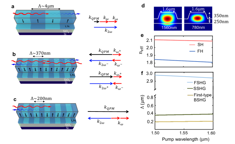
Figure 1 (a) shows the conventional FSHG configuration, where pump is injected from the left side of a periodically poled lithium niobate (PPLN) waveguide and the second-harmonic signal outputs from the right. The quasi-phase-matching condition for FSHG is , resulting in the poling period for first-order QPM to be several micrometers [Fig. 1 (f)]. When poling period is further reduced to submicron level, a novel type of QPM can be attained, as shown in Fig. 1 (b). Here the wave vectors of the two counter-propagating pumps mutually cancel with each other, necessitating a relatively large grating vector to achieve QPM according to . To fulfill this condition, the typical poling period is around 370nm for conversion between pump quasi-transverse magnetic (TM) mode at 1560 nm and second-harmonic quasi-transverse magnetic (TM) mode at 780 nm, as indicated in Fig. 1 (d). The first-type BSHG requires even more stringent QPM which results in poling period to be approximately 200 nm , as shown in Fig. 1 (c) and Fig. 1 (f). (See supplement 1, section 2 for detailed comparison between SSHG and the first-type BSHG).
Starting from the coupled mode equations describing nonlinear interaction between the pump and SH waves, we can derive the conversion efficiency of SSHG, which under lossless condition and undepleted pump approximation is given by
| (1) |
where is the second-order nonlinear coefficient, , are the effective refractive index and mode area for pump and SH modes, is the length of waveguide poling section and denotes the phase mismatching vector (see supplement 1, section 1). We note that this formula is consistent with that of the typical FSHG case [14], but the crucial difference arises from the phase mismatch vector . This element plays a critical role in converting the phase matching bandwidth, defined by , into a scale based on wavelength (), thus leading to a notable distinction between the two. Specifically, for SSHG, is given by , whereas for the ordinary SHG, it is . For the structure illustrated in Fig. 1 (d), the latter is approximately forty times larger. It’s possible to further reduce the phase matching bandwidth of SSHG by engineering or to be larger, thereby contributing to a narrower bandwidth in spontaneous down conversion for certain quantum photonics applications [52].
3 Design and Fabrication of Lithium Niobate Waveguide with Sub-wavelength Poling Period
Domain reversal of lithium niobate is driven by the applied external electric field E, which, in conjunction with the internal depolarizing field E and screening field E, determine the nucleation probability of reversed domains [53]. The latter two factor are material and geometry-specific, and under certain circumstances, they can even cancel each other out. Therefore, we perform 3D electrostatics simulation of the external electric field distribution using COMSOL to assess the probability of domain reversal as the poling period changes.
A voltage of 650V, similar to the previously reported experimental value [15], is applied to the electrode array, with the bottom Si acting as the ground. The electrode layout, shown by yellow in Fig. 2(a), is designed to create domain patterns that harvest the largest nonlinear coefficient (19.5 pm/V [54]) for SHG conversion from the TM00 pump mode to the TM00 SH mode. Figure 2 (a) displays the top-view and cross-sectional E-field distribution at the end of the poling electrodes with a period of 2.59 µm and duty cycle of 25% for illustration purposes. To evaluate how the electrode spacing affects poling quality, we analyze the corresponding E-field features at the top surface and the cross-section with fixed electrode duty cycle, respectively.
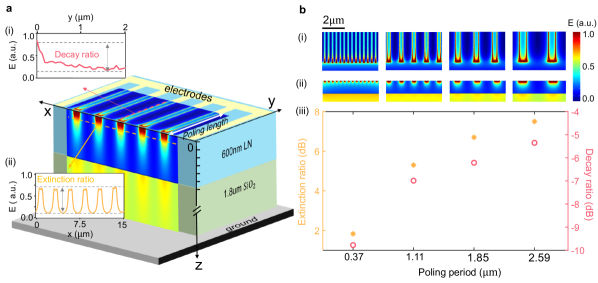
First, nucleation tends to initiate at the electrode edges due to the large fringing field present there [55, 56]. Therefore, we extract the E-field along the edge of an electrode and characterize its longitudinal decay rate as = 10log, as shown in Fig. 2 (a-i). 2 µm is the distance from the electrode end located at , and it’s chosen to be comparable to typical waveguide width. decreases rapidly as the poling period becomes smaller and reaches -10 dB at our targeted 370 nm period, as illustrated by red circles in Fig. 2 (b-iii). This indicates that the achievable poling length along the electrode, shown by white arrow on top surface in Fig. 2(a), is significantly reduced and requires more precise alignment between the waveguide and poling electrodes in device fabrication. Second, a high extinction fringing field between neighboring electrodes is desirable to preserve the original domain between them. The E-field along the orange line, situated 100 nm below the LN surface, is plotted in Fig. 2 (a-ii). Here, the extinction ratio (ER) of the E-field is defined as . The ER decreases significantly from 7.5 dB to 1.8 dB when the poling period is reduced from 2.59 µm to 370 nm, as indicated by oranges stars in Fig. 2 (b-iii). A reduced ER leads to excessive domain reversal beyond the designated electrode coverage area and increases the risk of overpoling. Consequently, a considerable reduction in electrode width is required to alleviate this effect for small poling periods.
Our fabrication starts with a 600 nm z-cut LNOI wafer. We first deposit 70 nm nickel electrodes through a liftoff process, with the electrode width being 15 of the poling period. Such a dense electrode array requires careful selection of ebeam resist and precise liftoff control. We use MMA/PMMA bilayer ebeam resist, followed by the 3:1 iced IPA:water developer for better resolution and gentle oxygen plasma descum to remove residual resist in the patterned area. Subsequently, the nickel electrode is deposited via the ebeam evaporator and liftoff in a 80 ∘C acetone bath aided by sonication. Upon completion of the electrode fabrication, the LN film undergoes poling through a 650 V voltage pulse lasting 10 ms at 250 ∘C. Finally, we pattern nanowaveguides in the periodically poled LN thin film using the same process described in our previous work [15]. Figure. 3 (a-i) and (b-i) present the false color scanning electron microscopy (SEM) images of waveguides with poling period being 1.11 µm and 370 nm, which are designed for third-order and first-order QPM, respectively.
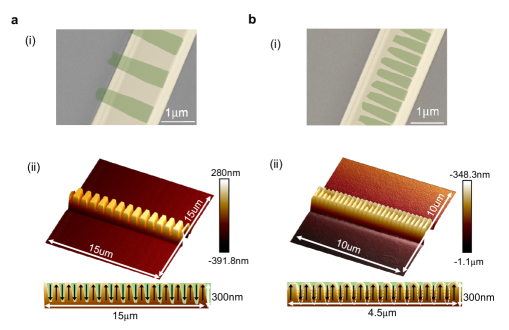
To examine the switched domains, we immerse the chip in Hydrofluoric (HF) acid for 3 mins. This duration is carefully chosen to selectively etch a portion of the reversed domains while preserving the waveguide’s adherence to the wafer for subsequent domain characterization. Then we use atomic force microscopy (AFM) to map the domain distribution for two poling periods, 1.11 µm and 370 nm. Fig. 3 (a-ii) and (b-ii) present 3D AFM images for each case, along with cross-sectional views. The duty cycle for the 1.11 µm period is approximately 50 as observed from the side view. However, limited HF etching time on the waveguide does not adequately expose the domain profile for the 370 nm period as excessive HF etching of the waveguides leads to their delamination from the substrate. To address this issue, we pole a separate chip consisting of only bare lithium niobate thin film under the same poling process and then apply HF etching for 20 minutes to completely removes the reversed domains without leading to the film detachment. Through this approach, the complete domain profile is exposed and mapped out by SEM and AFM and the volume duty cyle is calculated to be 37 (see supplement 1, section 3). The poling length along electrodes is measured to be 1.4 um , which is attributed to the large E-field decay ratio as illustrated by the simulation shown in Fig. 2(b).
4 Measurement of Symmetric Second Harmonic Generation
A tunable CW telecom laser (Santec 710) is split equally by a 50- coupler and used as pump laser. Each branch of the pump light enters the 1550 nm port of a wavelength-division multiplexer (WDM) and is subsequently coupled into the chip via lensed fibers. SSHG signals propagate in both left (LSHG) and right (RSHG) directions, exiting the WDM through its 780 nm port and being collected by two identical visible photon detectors. The fiber-to-chip insertion loss is calibrated to be 7.00.2 dB for infrared and 6.70.2dB for near visible.
We first inject the pump laser only from the left or only from the right side of an LN waveguide with 2 mm poling section. In this configuration, very weak SHG signals with similar magnitude are detected in both directions. For clarity, we only plot one of the SHG outputs, as shown by the lighter blue trace in Fig. 4 (a-i) and the lighter green curve in Fig. 4 (a-ii). This tiny amount of SH signal can be attributed to the pump back reflection at the waveguide facet. Subsequently, we activate the pump from both sides, resulting in two orders of magnitude higher SHG powers compared to the single-sided pump scenario. This observation confirms that the phase matching condition is satisfied only when two counter-propagating pump modes are present, i.e. . Under the assumption of uniform phase-matching throughout the waveguide and a symmetrical measurement setup, the spectra in both directions are supposed to be identical. Indeed, as depicted in Fig. 4 (a), the LSHG and RSHG are detected at the same pump wavelength with comparable power. The phase matching bandwidth is measured to be around 250 pm for both LSHG and RSHG, which matches well with the theoretical spectrum (gray curve) under the undepleted pump approximation. The oscillations within the main phase matching peak are attributed to the interference pattern of a Fabry-Perot cavity formed by the waveguide facets, whose cavity length of 14 mm gives rise to an pump FSR of 0.07 nm.
We delve further into the efficiency of SSHG in a waveguide with a 6 mm poling section. As depicted in Fig. 4 (b), the output powers for both left and right SHG increase quadratically with increasing pump power in the undepleted regime. The experimental normalized peak SHG efficiency is found to be around 1470 /W/ for both LSHG and RSHG, where , are one-sided pump and SHG power. Even though the achieved effciency is lower than the theoretical prediction 2050 /W/ due to waveguide-loss and deviation from the 50 duty cycle, the result still falls within the same order of magnitude with state-of-art efficiency in ordinary forward SHG in LN waveguide [14, 17]
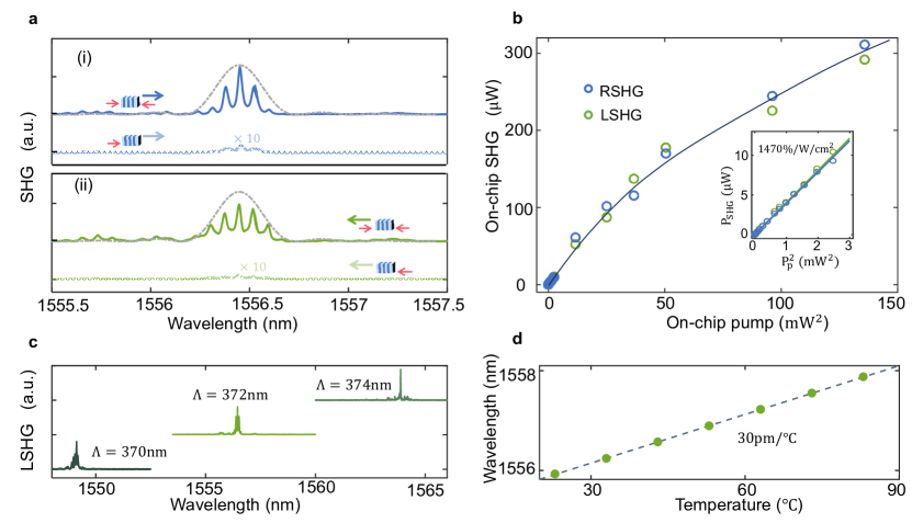
It is notable that the phase matching wavelength of SSHG strongly depends on the poling period according to . In contrast, the phase matching wavelength for FSHG, given by , which is far less sensitive to the poling period period changes (by a factor of ). As shown in Fig. 4(c), a 2 nm variation in the poling period results in a shift of 7.32 nm in the phase matching wavelength. This observation demonstrates that our technique can achieve nanometer-distinguishable poling periods and maintain excellent periodicity across several millimeters. Another noteworthy result is the suppressed temperature dependence of phase-matching wavelength of SSHG, as displayed in Fig. 4(d). In accordance with , the thermal shifting rate of is estimated to be 40 pmC [57] and experimentally measured to be 30 pmC, whereas for FSHG, and it’s estimated to be 107 pmC mainly due to the larger poling period.
5 Conclusion
In conclusion, we experimentally demonstrate symmetric second-harmonic generation in a sub-wavelength periodically-poled lithium niobate waveguide. Our simulations and experiments reveal that the poling period is largely limited by the 600 nm-thick LN film. Within the thin film, the poling field distribution dictates the achievable poling length along electrodes and the duty cycle. Further reduction of the poling period is possible with thinner LN films. Notably, the conversion efficiency under CW pump, measured at 1470, is on par with the state-of-the-art value for the forward SHG scheme in PPLN waveguide. The unique counter-propagating pump wave configuration of SSHG leads to a narrower phase-matching bandwidth and reduced thermal shift. This achievement in sub-wavelength poling of LN waveguides and the successful implementation of SSHG open new avenues for complex nonlinear optical processes and quantum networks, such as CW pumped mirrorless optical parametric oscillation and spatially separable twin-photon states. These advancements will further enrich the realm of nonlinear optics and quantum information processing.
Disclosures The authors declare no conflicts of interest.
Acknowledgments This project is supported in part by the National Science Foundation (NSF) through ERC Center for Quantum Networks (CQN) grant (grant no EEC-1941583) and an NSF FuSe grant (grant no 2235377). The part of the research that involves lithium niobate thin film preparation is supported by the US Department of Energy Co-design Center for Quantum Advantage (C2QA) under Contract No. DE-SC0012704. The authors would like to thank Yong Sun, Lauren Mccabe, Kelly Woods, and Michael Rooks for their assistance provided in the device fabrication. The fabrication of the devices was done at the Yale School of Engineering & Applied Science (SEAS) Cleanroom and the Yale Institute for Nanoscience and Quantum Engineering (YINQE).
Supplemental document See Supplement 1 for supporting content.
References
- [1] A. W. Bruch, X. Liu, Z. Gong, et al., “Pockels soliton microcomb,” \JournalTitleNature Photonics 15, 21–27 (2020).
- [2] J. Lu, D. N. Puzyrev, V. V. Pankratov, et al., “Two-colour dissipative solitons and breathers in microresonator second-harmonic generation,” \JournalTitleNat Commun 14, 2798 (2023).
- [3] J.-Q. Wang, Y.-H. Yang, M. Li, et al., “Synthetic five-wave mixing in an integrated microcavity for visible-telecom entanglement generation,” \JournalTitleNature Communications 13, 6223 (2022).
- [4] J. Szabados, B. Sturman, and I. Breunig, “Frequency comb generation threshold via second-harmonic excitation in optical microresonators,” \JournalTitleAPL Photonics 5 (2020).
- [5] J. Szabados, D. N. Puzyrev, Y. Minet, et al., “Frequency comb generation via cascaded second-order nonlinearities in microresonators,” \JournalTitlePhys Rev Lett 124, 203902 (2020).
- [6] C. Cui, L. Zhang, and L. Fan, “In situ control of effective kerr nonlinearity with pockels integrated photonics,” \JournalTitleNature Physics 18, 497–501 (2022).
- [7] M. Li, C.-L. Zou, C.-H. Dong, et al., “Enhancement of second-harmonic generation based on the cascaded second- and third-order nonlinear processes in a multimode optical microcavity,” \JournalTitlePhys. Rev. A 98, 013854 (2018).
- [8] D. T. Spencer, T. Drake, T. C. Briles, et al., “An optical-frequency synthesizer using integrated photonics,” \JournalTitleNature 557, 81–85 (2018).
- [9] S. B. Papp, K. Beha, P. Del’Haye, et al., “Microresonator frequency comb optical clock,” \JournalTitleOptica 1, 10–14 (2014).
- [10] J. Zhao, C. Ma, M. Rüsing, and S. Mookherjea, “High quality entangled photon pair generation in periodically poled thin-film lithium niobate waveguides,” \JournalTitlePhys. Rev. Lett. 124, 163603 (2020).
- [11] J. Lu, M. Li, C.-L. Zou, et al., “Toward 1% single-photon anharmonicity with periodically poled lithium niobate microring resonators,” \JournalTitleOptica 7, 1654–1659 (2020).
- [12] X. Lu, Q. Li, D. A. Westly, et al., “Chip-integrated visible–telecom entangled photon pair source for quantum communication,” \JournalTitleNature physics 15, 373–381 (2019).
- [13] H. S. Stokowski, T. P. McKenna, T. Park, et al., “Integrated quantum optical phase sensor in thin film lithium niobate,” \JournalTitleNature Communications 14, 3355 (2023).
- [14] C. Wang, C. Langrock, A. Marandi, et al., “Ultrahigh-efficiency wavelength conversion in nanophotonic periodically poled lithium niobate waveguides,” \JournalTitleOptica 5 (2018).
- [15] J. Lu, J. B. Surya, X. Liu, et al., “Periodically poled thin-film lithium niobate microring resonators with a second-harmonic generation efficiency of 250,000%/w,” \JournalTitleOptica 6, 1455 (2019).
- [16] J.-Y. Chen, Z.-H. Ma, Y. M. Sua, et al., “Ultra-efficient frequency conversion in quasi-phase-matched lithium niobate microrings,” \JournalTitleOptica 6 (2019).
- [17] A. A. Sayem, Y. Wang, J. Lu, et al., “Efficient and tunable blue light generation using lithium niobate nonlinear photonics,” \JournalTitleApplied Physics Letters 119 (2021).
- [18] A. Boes, L. Chang, C. Langrock, et al., “Lithium niobate photonics: Unlocking the electromagnetic spectrum,” \JournalTitleScience 379, eabj4396 (2023).
- [19] J. S. Levy, M. A. Foster, A. L. Gaeta, and M. Lipson, “Harmonic generation in silicon nitride ring resonators,” \JournalTitleOptics express 19, 11415–11421 (2011).
- [20] E. Timurdogan, C. V. Poulton, M. J. Byrd, and M. R. Watts, “Electric field-induced second-order nonlinear optical effects in silicon waveguides,” \JournalTitleNature Photonics 11, 200–206 (2017).
- [21] X. Lu, G. Moille, A. Rao, et al., “Efficient photoinduced second-harmonic generation in silicon nitride photonics,” \JournalTitleNature Photonics 15, 131–136 (2021).
- [22] I. Roland, M. Gromovyi, Y. Zeng, et al., “Phase-matched second harmonic generation with on-chip gan-on-si microdisks,” \JournalTitleScientific reports 6, 34191 (2016).
- [23] C. Xiong, W. Pernice, K. K. Ryu, et al., “Integrated gan photonic circuits on silicon (100) for second harmonic generation,” \JournalTitleOpt. Express 19, 10462–10470 (2011).
- [24] X. Liu, A. W. Bruch, and H. X. Tang, “Aluminum nitride photonic integrated circuits: from piezo-optomechanics to nonlinear optics,” \JournalTitleAdv. Opt. Photon. 15, 236–317 (2023).
- [25] X. Guo, C.-L. Zou, and H. X. Tang, “Second-harmonic generation in aluminum nitride microrings with 2500%/w conversion efficiency,” \JournalTitleOptica 3, 1126 (2016).
- [26] A. W. Bruch, X. Liu, X. Guo, et al., “17000/w second-harmonic conversion efficiency in single-crystalline aluminum nitride microresonators,” \JournalTitleApplied Physics Letters 113 (2018).
- [27] J. A. Armstrong, N. Bloembergen, J. Ducuing, and P. S. Pershan, “Interactions between light waves in a nonlinear dielectric,” \JournalTitlePhys. Rev. 127, 1918–1939 (1962).
- [28] M. M. Fejer, G. Magel, D. H. Jundt, and R. L. Byer, “Quasi-phase-matched second harmonic generation: tuning and tolerances,” \JournalTitleIEEE Journal of quantum electronics 28, 2631–2654 (1992).
- [29] A. Boes, L. Chang, C. Langrock, et al., “Lithium niobate photonics: Unlocking the electromagnetic spectrum,” \JournalTitleScience 379, eabj4396 (2023).
- [30] D. Zhu, L. Shao, M. Yu, et al., “Integrated photonics on thin-film lithium niobate,” \JournalTitleAdvances in Optics and Photonics 13, 242–352 (2021).
- [31] R. Luo, Y. He, H. Liang, et al., “Highly tunable efficient second-harmonic generation in a lithium niobate nanophotonic waveguide,” \JournalTitleOptica 5, 1006–1011 (2018).
- [32] P.-K. Chen, I. Briggs, C. Cui, et al., “Adapted poling to break the nonlinear efficiency limit in nanophotonic lithium niobate waveguides,” (2023).
- [33] X. Gu, R. Y. Korotkov, Y. J. Ding, et al., “Backward second-harmonic generation in periodically poled lithium niobate,” \JournalTitleJOSA B 15, 1561–1566 (1998).
- [34] Y. J. Ding and J. B. Khurgin, “Second-harmonic generation based on quasi-phase matching: a novel configuration,” \JournalTitleOptics letters 21, 1445–1447 (1996).
- [35] C. Canalias, V. Pasiskevicius, M. Fokine, and F. Laurell, “Backward quasi-phase-matched second-harmonic generation in submicrometer periodically poled flux-grown KTiOPO4,” \JournalTitleApplied Physics Letters 86, 181105 (2005).
- [36] X. Gu, M. Makarov, Y. J. Ding, et al., “Backward second-harmonic and third-harmonic generation in a periodically poled potassium titanyl phosphate waveguide,” \JournalTitleOptics letters 24, 127–129 (1999).
- [37] J. U. Kang, Y. J. Ding, W. K. Burns, and J. S. Melinger, “Backward second-harmonic generation in periodically poled bulk LiNbO3,” \JournalTitleOptics letters 22, 862–864 (1997).
- [38] P. Mutter, K. M. Mølster, A. Zukauskas, et al., “Efficient first-order quasi-phase-matched backward second-harmonic generation,” \JournalTitleOpt. Lett. 48, 1534–1537 (2023).
- [39] A. C. Busacca, S. Stivala, L. Curcio, et al., “Backward frequency doubling of near infrared picosecond pulses,” \JournalTitleOpt. Express 22, 7544–7549 (2014).
- [40] S. Stivala, A. C. Busacca, L. Curcio, et al., “Continuous-wave backward frequency doubling in periodically poled lithium niobate,” \JournalTitleApplied Physics Letters 96, 111110 (2010).
- [41] J. T. Nagy and R. M. Reano, “Submicrometer periodic poling of lithium niobate thin films with bipolar preconditioning pulses,” \JournalTitleOptical Materials Express 10 (2020).
- [42] B. N. Slautin, H. Zhu, and V. Y. Shur, “Submicron periodical poling in z-cut lithium niobate thin films,” \JournalTitleFerroelectrics 576, 119–128 (2021).
- [43] B. Slautin, H. Zhu, and V. Y. Shur, “Submicron periodical poling by local switching in ion sliced lithium niobate thin films with a dielectric layer,” \JournalTitleCeramics International 47, 32900–32904 (2021).
- [44] D. S. Chezganov, E. O. Vlasov, E. A. Pashnina, et al., “Domain patterning of non-polar cut lithium niobate by focused ion beam,” \JournalTitleFerroelectrics 559, 66–76 (2020).
- [45] I. Krasnokutska, J.-L. J. Tambasco, and A. Peruzzo, “Submicron domain engineering in periodically poled lithium niobate on insulator,” (2021).
- [46] C. Liljestrand, A. Zukauskas, V. Pasiskevicius, and C. Canalias, “Highly efficient mirrorless optical parametric oscillator pumped by nanosecond pulses,” \JournalTitleOpt Lett 42, 2435–2438 (2017).
- [47] C. Canalias and V. Pasiskevicius, “Mirrorless optical parametric oscillator,” \JournalTitleNature Photonics 1, 459–462 (2007).
- [48] S. E. Harris, “Proposed backward wave oscillation in the infrared,” \JournalTitleApplied Physics Letters 9, 114–116 (1966).
- [49] A. Godard, M. Guionie, J.-B. Dherbecourt, et al., “Backward optical parametric oscillator threshold and linewidth studies,” \JournalTitleJournal of the Optical Society of America B 39 (2022).
- [50] R. S. Coetzee, A. Zukauskas, C. Canalias, and V. Pasiskevicius, “Low-threshold, mid-infrared backward-wave parametric oscillator with periodically poled Rb:KTP,” \JournalTitleAPL Photonics 3 (2018).
- [51] P. S. Kuo, D. V. Reddy, V. Verma, et al., “Photon-pair production and frequency translation using backward-wave spontaneous parametric downconversion,” \JournalTitleOptica Quantum 1, 43–48 (2023).
- [52] K.-H. Luo, V. Ansari, M. Massaro, et al., “Counter-propagating photon pair generation in a nonlinear waveguide,” \JournalTitleOptics Express 28, 3215–3225 (2020).
- [53] V. Y. Shur, E. Rumyantsev, R. Batchko, et al., “Domain kinetics in the formation of a periodic domain structure in lithium niobate,” \JournalTitlePhysics of the solid state 41, 1681–1687 (1999).
- [54] I. Shoji, T. Kondo, A. Kitamoto, et al., “Absolute scale of second-order nonlinear-optical coefficients,” \JournalTitleJOSA B 14, 2268–2294 (1997).
- [55] S. B. Lang, H. L. Chan, and V. Y. Shur, “Kinetics of ferroelectric domains:application of general approach to LiNbO3 and LiTaO3,” \JournalTitleFrontiers of Ferroelectricity: A Special Issue of the Journal of Materials Science pp. 199–210 (2007).
- [56] G. Rosenman, K. Garb, A. Skliar, et al., “Domain broadening in quasi-phase-matched nonlinear optical devices,” \JournalTitleApplied Physics Letters 73, 865–867 (1998).
- [57] L. Moretti, M. Iodice, F. G. Della Corte, and I. Rendina, “Temperature dependence of the thermo-optic coefficient of lithium niobate, from 300 to 515 K in the visible and infrared regions,” \JournalTitleJournal of Applied Physics 98, 036101 (2005).