Large spin-orbit torque in a-plane -Fe2O3/Pt bilayers
Abstract
Realization of efficient spin-orbit torque switching of the Néel vector in insulating antiferromagnets is a challenge, often complicated by spurious effects. Quantifying the spin-orbit torques in antiferromagnet/heavy metal heterostructures is an important first step towards this goal. Here, we employ magneto-optic techniques to study damping-like spin-orbit torque (DL-SOT) in a-plane -Fe2O3 (hematite) with a Pt spin-orbit overlayer. We find that the DL-SOT efficiency is two orders of magnitude larger than reported in c- and r-plane hematite/Pt using harmonic Hall techniques. The large magnitude of DL-SOT is supported by direct imaging of current-induced motion of antiferromagnetic domains that happens at moderate current densities. Our study introduces a new method for quantifying spin-orbit torque in antiferromagnets with a small canted moment and identifies a-plane -Fe2O3 as a promising candidate to realize efficient SOT switching.
 \SetHorizontalCoffin\labelcoffin
(a)\SetVerticalPole\imagecoffinleft-0pt+\CoffinWidth\labelcoffin/2\SetVerticalPole\imagecoffinright\Width-3pt-\CoffinWidth\labelcoffin/2\SetHorizontalPole\imagecoffinup\Height+10pt-\CoffinHeight\labelcoffin/2\SetHorizontalPole\imagecoffindown3pt+\CoffinHeight\labelcoffin/2\JoinCoffins\imagecoffin[left,up]\labelcoffin[vc,hc]\TypesetCoffin\imagecoffin
 \SetHorizontalCoffin\labelcoffin
(c)\SetVerticalPole\imagecoffinleft-0pt+\CoffinWidth\labelcoffin/2\SetVerticalPole\imagecoffinright\Width-3pt-\CoffinWidth\labelcoffin/2\SetHorizontalPole\imagecoffinup\Height+10pt-\CoffinHeight\labelcoffin/2\SetHorizontalPole\imagecoffindown3pt+\CoffinHeight\labelcoffin/2\JoinCoffins\imagecoffin[left,up]\labelcoffin[vc,hc]\TypesetCoffin\imagecoffin
 \SetHorizontalCoffin\labelcoffin
(e)\SetVerticalPole\imagecoffinleft-0pt+\CoffinWidth\labelcoffin/2\SetVerticalPole\imagecoffinright\Width-3pt-\CoffinWidth\labelcoffin/2\SetHorizontalPole\imagecoffinup\Height+10pt-\CoffinHeight\labelcoffin/2\SetHorizontalPole\imagecoffindown3pt+\CoffinHeight\labelcoffin/2\JoinCoffins\imagecoffin[left,up]\labelcoffin[vc,hc]\TypesetCoffin\imagecoffin
 \SetHorizontalCoffin\labelcoffin
(b)\SetVerticalPole\imagecoffinleft-0pt+\CoffinWidth\labelcoffin/2\SetVerticalPole\imagecoffinright\Width-3pt-\CoffinWidth\labelcoffin/2\SetHorizontalPole\imagecoffinup\Height+10pt-\CoffinHeight\labelcoffin/2\SetHorizontalPole\imagecoffindown3pt+\CoffinHeight\labelcoffin/2\JoinCoffins\imagecoffin[left,up]\labelcoffin[vc,hc]\TypesetCoffin\imagecoffin
 \SetHorizontalCoffin\labelcoffin
(d)\SetVerticalPole\imagecoffinleft-0pt+\CoffinWidth\labelcoffin/2\SetVerticalPole\imagecoffinright\Width-3pt-\CoffinWidth\labelcoffin/2\SetHorizontalPole\imagecoffinup\Height+10pt-\CoffinHeight\labelcoffin/2\SetHorizontalPole\imagecoffindown3pt+\CoffinHeight\labelcoffin/2\JoinCoffins\imagecoffin[left,up]\labelcoffin[vc,hc]\TypesetCoffin\imagecoffin
 \SetHorizontalCoffin\labelcoffin
(f)\SetVerticalPole\imagecoffinleft-0pt+\CoffinWidth\labelcoffin/2\SetVerticalPole\imagecoffinright\Width-3pt-\CoffinWidth\labelcoffin/2\SetHorizontalPole\imagecoffinup\Height+10pt-\CoffinHeight\labelcoffin/2\SetHorizontalPole\imagecoffindown3pt+\CoffinHeight\labelcoffin/2\JoinCoffins\imagecoffin[left,up]\labelcoffin[vc,hc]\TypesetCoffin\imagecoffin
Antiferromagnets (AFMs) display fast spin dynamics, produce no stray fields, and are robust against magnetic fields due to their vanishing magnetization. Thus, in principle, they can offer faster and denser magnetic memory than spintronic devices based on conventional ferromagnetic (FM) materials [1, 2, 3]. Efficient electrical control of antiferromagnetic order is one of the holy grails of antiferromagnetic spintronics. Spin-orbit torque (SOT) is an efficient way to manipulate magnetic order in ferromagnets [4, 5, 6, 7], however, effects of SOT on antiferromagnets are less studied. In insulating AFM/heavy-metal (HM) bilayers, SOT switching is often complicated by spurious thermal effects arising from large electrical currents that are needed for the switching [8, 9, 10, 11, 12]. Therefore, developing alternative methods for characterizing the SOT in AFM/HM is an important step towards understanding SOT physics in these materials and realizing efficient electrical control. Current-modulated magneto-optic Kerr effect (MOKE) is a powerful technique for characterizing SOT [13, 14]. Although this technique has been extensively applied to FMs [13, 14, 15, 16, 17], its application to SOT in AFMs has been mostly unexplored.
In this Letter, we report large damping-like SOT in antiferromagnetic a-plane -Fe2O3/Pt as characterized by current-modulated MOKE. The magneto-optic detection is facilitated by the presence of a small canted moment in -Fe2O3 generated by the Dzyaloshinskii–Moriya interaction. Indeed, we find that from the experimental geometry point of view, a-plane -Fe2O3 behaves similar to the case of a ferromagnetic material with perpendicular magnetic anisotropy (PMA). To properly analyze current-modulated MOKE data, we develop a model that accounts for the antiferromagnetic nature of -Fe2O3. Comparing the model with the experimental results, we find that the DL-SOT efficiency in a-plane hematite/Pt bilayers is two orders of magnitude larger than reported in c-plane and r-plane samples [18, 19]. Using MOKE microscopy, we directly observe current-induced motion of antiferromagnetic domains that happens at moderate current densities, which corroborates the large magnitude of the DL-SOT. While our experimental geometry allows one to quantify only the damping-like component of the torque, we believe that this approach can be applied to other AFMs with a small canted moment. Our study identifies a-plane -Fe2O3 as a promising candidate to realize efficient SOT switching and calls for the development of hematite thin films with a-plane orientation.
To quantify the SOT in a-plane -Fe2O3/Pt bilayers using current-modulated MOKE technique, we modify the calibration method that allows converting from MOKE units in radians to effective SOT field in Teslas [15], since calibration by a small Oersted field does not result in a measurable signal. We first demonstrate the validity of our modified approach by applying it to a well-studied material, thulium iron garnet Tm3Fe5O12 (TmIG), an insulating ferrimagnet with perpendicular magnetic anisotropy.
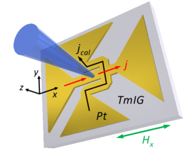
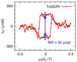
TmIG/Pt films with 8/5 nm thickness are grown by off-axis magnetron sputtering [20] and patterned into a device geometry shown in Fig. 1a by a combination of photolithography and argon ion milling. The device channel width is 20 m. We detect the out-of-plane magnetization, , using the polar MOKE geometry and measuring the Kerr ellipticity of a linearly polarized laser light reflected from the sample. The laser beam is focused on the sample surface to 5 m spot size, the wavelength of the light is 400 nm. Fig. 1b shows a Kerr ellipticity (KE) hysteresis loop with external magnetic field applied along hard-axis of TmIG. When is larger than the anisotropy field , the TmIG magnetization is along direction. With the current applied along the axis as well, the spin Hall effect (SHE) in the Pt layer generates spin current with polarization along axis. In this geometry, the effective damping-like field results into a small tilt of magnetization towards the sample normal, thus inducing an out-of-plane component . For and a small effective damping-like field the out-of-plane current-induced magnetization can be written as:
| (1) |
where is Kerr ellipticity that corresponds to the magnetization being fully out-of-plane.
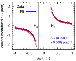
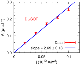
The current-modulated Kerr ellipticity is detected using a combination of quarter-wave plate, half-wave plate, Wollaston prism, balanced photodetector and lock-in amplifier at the frequency of the applied ac current. Fig. 1c shows as a function of magnetic field for a current density of A/m2. Following eq. (3), the data can be fitted using expression with two fitting parameters and , where . Measuring current-modulated KE at different current densities, we verify that scales linearly with , as expected for the effective SOT field. The current density dependence is plotted in Fig. 1e. Using the slope normalized by , extracted as a half of the hysteresis loop opening at in Fig. 1b, one can estimate the DL-SOT efficiency:
| (2) |
Using the measured values rad T per 1012 A/m2, rad, and nm along with kA/m from the literature (saturation magnetization of TmIG [20]), we estimate the effective DL-SOT field and efficiency to be mT per 1012 A/m2 and , respectively. This agrees well with studies on insulating FM/HM bilayers, in which DL-SOT efficiency have been found to be smaller than in metallic FM/HM. Literature on TmIG/Pt reports values of SOT efficiency [21, 22]. We note that to correctly estimate , the magnetic material should be in a single domain state within the laser spot size (at ) or the out-of-plane hysteresis loop should be measured to extract .
 \SetHorizontalCoffin\labelcoffin
(a)\SetVerticalPole\imagecoffinleft-0pt+\CoffinWidth\labelcoffin/2\SetVerticalPole\imagecoffinright\Width-3pt-\CoffinWidth\labelcoffin/2\SetHorizontalPole\imagecoffinup\Height+10pt-\CoffinHeight\labelcoffin/2\SetHorizontalPole\imagecoffindown3pt+\CoffinHeight\labelcoffin/2\JoinCoffins\imagecoffin[left,up]\labelcoffin[vc,hc]\TypesetCoffin\imagecoffin
 \SetHorizontalCoffin\labelcoffin
(b)\SetVerticalPole\imagecoffinleft-0pt+\CoffinWidth\labelcoffin/2\SetVerticalPole\imagecoffinright\Width-3pt-\CoffinWidth\labelcoffin/2\SetHorizontalPole\imagecoffinup\Height+10pt-\CoffinHeight\labelcoffin/2\SetHorizontalPole\imagecoffindown3pt+\CoffinHeight\labelcoffin/2\JoinCoffins\imagecoffin[left,up]\labelcoffin[vc,hc]\TypesetCoffin\imagecoffin
 \SetHorizontalCoffin\labelcoffin
(c)\SetVerticalPole\imagecoffinleft-0pt+\CoffinWidth\labelcoffin/2\SetVerticalPole\imagecoffinright\Width-3pt-\CoffinWidth\labelcoffin/2\SetHorizontalPole\imagecoffinup\Height+10pt-\CoffinHeight\labelcoffin/2\SetHorizontalPole\imagecoffindown3pt+\CoffinHeight\labelcoffin/2\JoinCoffins\imagecoffin[left,up]\labelcoffin[vc,hc]\TypesetCoffin\imagecoffin
 \SetHorizontalCoffin\labelcoffin
(d)\SetVerticalPole\imagecoffinleft-0pt+\CoffinWidth\labelcoffin/2\SetVerticalPole\imagecoffinright\Width-3pt-\CoffinWidth\labelcoffin/2\SetHorizontalPole\imagecoffinup\Height+10pt-\CoffinHeight\labelcoffin/2\SetHorizontalPole\imagecoffindown3pt+\CoffinHeight\labelcoffin/2\JoinCoffins\imagecoffin[left,up]\labelcoffin[vc,hc]\TypesetCoffin\imagecoffin
 \SetHorizontalCoffin\labelcoffin
(e)\SetVerticalPole\imagecoffinleft-0pt+\CoffinWidth\labelcoffin/2\SetVerticalPole\imagecoffinright\Width-3pt-\CoffinWidth\labelcoffin/2\SetHorizontalPole\imagecoffinup\Height+10pt-\CoffinHeight\labelcoffin/2\SetHorizontalPole\imagecoffindown3pt+\CoffinHeight\labelcoffin/2\JoinCoffins\imagecoffin[left,up]\labelcoffin[vc,hc]\TypesetCoffin\imagecoffin
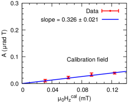
While the TmIG/Pt results agree well with reported values, we verify the validity of the experimental approach further using a calibration of effective DL-SOT field by Oersted field generated by a wire of a known geometry [13, 15]. The current path for the calibration wire in our device is shown in Fig. 1a and is labeled as . Fig. 1d shows the current-modulated KE response to an out-of-plane Oersted field generated by a calibration wire. Unlike the effective DL-SOT field, , that flips sign upon magnetic field reversal (Fig. 1c), the Oersted field is independent of . Thus, the Oersted-field-induced MOKE signal has even symmetry with respect to the magnetic field, as demonstrated in Fig. 1d. Using Ampere’s law, we calculate the magnetic field generated by the wire (drawn in Fig. 1a). For the maximal applied current of 8 mA, the COMSOL simulation yields a magnetic field of 0.124 mT. Thus we can calibrate the MOKE signal due to the effective DL-SOT against the Oersted field. Fig. 1f shows the current-modulated MOKE signal as a function of the Oersted field generated by current in the calibration wire. Using the slopes in Fig. 1e and 1f, we find mT per 1012 A/m2, which within experimental errors agrees with the value estimated by the normalization method. We note that the normalization method might be advantageous in the situation where the Oersted field is not strong enough to induce a reliable MOKE response, which we have found to be the case for our -Fe2O3/Pt devices.
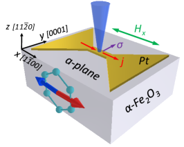
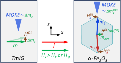
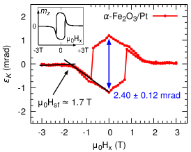
Having verified that our modified approach is valid, we discuss the spin-orbit torque measurements in a-plane -Fe2O3/Pt (bulk/5 nm). A commercial bulk crystal with dimensions mm and (110) cut (a-plane) is purchased from MTI Corporation. 5 nm Pt is deposited by magnetron sputtering at room temperature. The geometry of the current-modulated MOKE experiment, Fig. 2a, is similar to the measurements on TmIG/Pt, with a difference that now the spin-flop field, , is needed to align the magnetization along direction, instead of the anisotropy field . Fig. 2b illustrates the difference between the action of damping-like spin-orbit torque on ferrimagnetic TmIG and antiferromagnetic -Fe2O3. Charge current through the Pt layer is applied along the [100] direction (-axis in Fig. 2a) and as a result, the spin polarization is along [0001] (-axis). The effective damping-like field acts on the magnetic moments of both sublattices: and . The two torques act constructively to rotate the Néel vector and the canted magnetic moment () in the basal plane. For , the is rotated out of the sample plane and the resultant out-of-plane component can be detected by current-modulated polar MOKE.
Kerr ellipticity as a function of magnetic field swept along [100] direction () is plotted in Fig. 2c. Somewhat surprisingly, the KE signal due to the small canted moment in antiferromagnetic -Fe2O3 is large, mrad, roughly times larger than for ferrimagnetic TmIG. This could be explained by the larger thickness of -Fe2O3 vs TmIG (bulk vs 8 nm) and the difference in magneto-optic coefficients at 400 nm. The spin-flop field can be estimated from KE hysteresis loop along [100], as shown in Fig. 2c, T, which agrees with an estimation based on spin Hall magnetoresistance measurements, T, see SM Sec. S2 [23] for details.
We also simulate vs numerically (see SM Sec. S4 [23] for details). Setting the exchange field T, anisotropy field in the basal plane T, DMI field T, which are close to values reported in the literature [24, 25, 26, 27, 28], and a misalignment angle of between the external magnetic field and the [100] crystallographic direction, we are able to qualitatively reproduce the experimental data. The simulated hysteresis loop is shown in the inset of Fig. 2c. We note that an exact shape of the hysteresis loop is sensitive to the misalignment angle of the magnetic field.
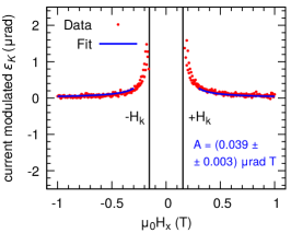
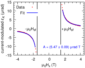
The current-modulated Kerr ellipticity as a function of magnetic field for a current density of A/m2 is shown in Fig. 2d. We show that for , the data can be fitted using an expression (see SM Sec. S4 [23]):
| (3) |
We fix to a value of 2.5 T as it is more established in the literature [24, 25, 26, 27, 28] and fit the current-modulated Kerr ellipticity data using two fitting parameters and . The result of the fit is the blue curve in Fig. 2d.
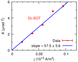
Next, we measure the current-modulated MOKE signal at different current densities and repeat the fitting procedure. As shown in Fig. 2e, we observe that scales linearly with current density , consistent with SOT origin of the MOKE signal. Similar to TmIG/Pt analysis, using the measured values of the slope rad T per 1012 A/m2 and mrad, we can estimate the effective DL-SOT field. We find mT per 1012 A/m2. We note that the fitting is not too sensitive to the fixed value of the DMI field. Varying the value in the T range changes the value of only by 20%.
The value is two orders of magnitude larger than effective DL-SOT field reported in c-plane and r-plane hematite using the harmonic Hall technique [18, 19] and larger than values for thick metallic FM/Pt bilayers [4]. We note that we study a bulk sample and that even larger should be expected for thin films. We also point out that in c-plane -Fe2O3, points along the c-axis and thus it needs to overcome the strong easy-plane anisotropy in order to realize the switching. For r-plane orientation, this effect is mitigated, while for a-plane orientation, fully lies within the easy-plane, and consequently, its effect on the rotation of the Néel vector is maximized. Thus, a-plane -Fe2O3/Pt might be a promising material system to realize efficient SOT switching of the Néel vector. To check that our results are robust to a different location on the sample, device geometry, and optical alignment, we reproduce results on a different -Fe2O3/Pt device. The data on the other device are shown in the SM Sec. S3 [23]. We find mT per 1012 A/m2, which agrees well with the result on the device shown in Fig. 2.
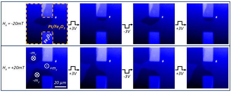
Finally, we utilize MOKE microscopy to directly image AFM domains in a-plane -Fe2O3/Pt. Fig. 3 shows polar MOKE maps of a m wide and m long device. Large, tens of micrometers in size, AFM domains with a canted moment along (light blue) and (dark blue) direction are observed. Using a small bias field, mT, we demonstrate current-driven AFM domain motion. For mT, a domain in the center of the device reproducibly shrinks (expands) after a positive V (negative V) pulse that corresponds to a moderate current density of A/m2. The duration of pulses is 10 s. When the bias field is reversed to mT, the polarity of the domain motion changes. Now, a domain shrinks (expands) after a positive V (negative V) pulse. This behavior is fully consistent with a protocol for damping-like SOT-driven domain motion in FM/HM bilayers [29]. The SOT-driven motion of AFM domain at moderate current densities supports the large measured value of DL-SOT efficiency. We note that for many AFMs, synchrotron facilities are needed for direct imaging of AFM domains [9, 12, 30], whereas our results show that domains in a-plane -Fe2O3 can be readily imaged by a table-top technique.
It is theoretically suggested that the damping-like SOT, not the field-like one, is needed to switch the Néel vector [1]. The magnitude of the damping-like SOT measured in our work is considerably larger compared to previous reports on -Fe2O3/HM bilayers [18, 19]. This is great news for the efficient electrical control of the AFM order, but it also raises a question about the origin of the enhanced torque. It was proposed that a low spin-mixing conductance of the thin film -Fe2O3/HM interface can explain a small magnitude of the damping-like SOT [18, 19]. Consequently, a high spin-mixing conductance of the a-plane terminated -Fe2O3 interface could account for the enhanced DL-SOT in our samples. Contrary to these works, a spin-pumping study on bulk c-plane -Fe2O3/HM samples [28] estimated the spin-mixing conductance to be two orders of magnitude larger than those reported in other FM/HM and AFM/FM systems. This indicates that the quality of the thin films and bulk crystals could differ significantly. We believe that more studies are needed to systematically investigate the interface between -Fe2O3 and a heavy metal, in order to understand and maximize the SOT in this promising material system.
In conclusion, we utilized current-modulated MOKE to characterize spin-orbit torque in a-plane -Fe2O3/Pt bilayers. We found that damping-like SOT is two orders of magnitude larger than reported in c-plane and r-plane samples. Our study identifies a-plane -Fe2O3 as a promising candidate to realize efficient SOT switching and calls for the development of thin films with a-plane orientation.
This research was primarily supported (I.L., D.R., F.Y., R.K.K.) by the Center for Emergent Materials, an NSF MRSEC, under award number DMR-2011876 and partially supported (J.M., F.Y.) by the Department of Energy, Office of Science, Basic Energy Sciences, under Grant No. DE-SC0001304. R.C. and H.Z. were supported by the Air Force Office of Scientific Research under Grant No. FA9550-19-1-0307.
References
- Baltz et al. [2018] V. Baltz, A. Manchon, M. Tsoi, T. Moriyama, T. Ono, and Y. Tserkovnyak, Antiferromagnetic spintronics, Rev. Mod. Phys. 90, 015005 (2018).
- Fukami et al. [2020] S. Fukami, V. O. Lorenz, and O. Gomonay, Antiferromagnetic spintronics, Journal of Applied Physics 128, 070401 (2020).
- Han et al. [2023] J. Han, R. Cheng, L. Liu, H. Ohno, and S. Fukami, Coherent antiferromagnetic spintronics, Nat. Mater. 22, 684 (2023).
- Liu et al. [2011] L. Liu, T. Moriyama, D. C. Ralph, and R. A. Buhrman, Spin-Torque Ferromagnetic Resonance Induced by the Spin Hall Effect, Phys. Rev. Lett. 106, 036601 (2011).
- Miron et al. [2011] I. M. Miron, K. Garello, G. Gaudin, P.-J. Zermatten, M. V. Costache, S. Auffret, S. Bandiera, B. Rodmacq, A. Schuhl, and P. Gambardella, Perpendicular switching of a single ferromagnetic layer induced by in-plane current injection, Nature 476, 189 (2011).
- Liu et al. [2012] L. Liu, C.-F. Pai, Y. Li, H. W. Tseng, D. C. Ralph, and R. A. Buhrman, Spin-Torque Switching with the Giant Spin Hall Effect of Tantalum, Science 336, 555 (2012).
- Manchon et al. [2019] A. Manchon, J. Železný, I. Miron, T. Jungwirth, J. Sinova, A. Thiaville, K. Garello, and P. Gambardella, Current-induced spin-orbit torques in ferromagnetic and antiferromagnetic systems, Rev. Mod. Phys. 91, 035004 (2019).
- Chiang et al. [2019] C. Chiang, S. Huang, D. Qu, P. Wu, and C. Chien, Absence of Evidence of Electrical Switching of the Antiferromagnetic Néel Vector, Phys. Rev. Lett. 123, 227203 (2019).
- Baldrati et al. [2019] L. Baldrati, O. Gomonay, A. Ross, M. Filianina, R. Lebrun, R. Ramos, C. Leveille, F. Fuhrmann, T. R. Forrest, F. Maccherozzi, S. Valencia, F. Kronast, E. Saitoh, J. Sinova, and M. Kläui, Mechanism of N\’eel Order Switching in Antiferromagnetic Thin Films Revealed by Magnetotransport and Direct Imaging, Phys. Rev. Lett. 123, 177201 (2019).
- Zhang et al. [2019] P. Zhang, J. Finley, T. Safi, and L. Liu, Quantitative Study on Current-Induced Effect in an Antiferromagnet Insulator/Pt Bilayer Film, Phys. Rev. Lett. 123, 247206 (2019).
- Churikova et al. [2020] A. Churikova, D. Bono, B. Neltner, A. Wittmann, L. Scipioni, A. Shepard, T. Newhouse-Illige, J. Greer, and G. S. D. Beach, Non-magnetic origin of spin Hall magnetoresistance-like signals in Pt films and epitaxial NiO/Pt bilayers, Applied Physics Letters 116, 022410 (2020).
- Meer et al. [2021] H. Meer, F. Schreiber, C. Schmitt, R. Ramos, E. Saitoh, O. Gomonay, J. Sinova, L. Baldrati, and M. Kläui, Direct Imaging of Current-Induced Antiferromagnetic Switching Revealing a Pure Thermomagnetoelastic Switching Mechanism in NiO, Nano Lett. 21, 114 (2021).
- Fan et al. [2014] X. Fan, H. Celik, J. Wu, C. Ni, K.-J. Lee, V. O. Lorenz, and J. Q. Xiao, Quantifying interface and bulk contributions to spin–orbit torque in magnetic bilayers, Nat Commun 5, 3042 (2014).
- Fan et al. [2016] X. Fan, A. R. Mellnik, W. Wang, N. Reynolds, T. Wang, H. Celik, V. O. Lorenz, D. C. Ralph, and J. Q. Xiao, All-optical vector measurement of spin-orbit-induced torques using both polar and quadratic magneto-optic Kerr effects, Applied Physics Letters 109, 122406 (2016).
- Wang et al. [2019] W. Wang, T. Wang, V. P. Amin, Y. Wang, A. Radhakrishnan, A. Davidson, S. R. Allen, T. J. Silva, H. Ohldag, D. Balzar, B. L. Zink, P. M. Haney, J. Q. Xiao, D. G. Cahill, V. O. Lorenz, and X. Fan, Anomalous spin–orbit torques in magnetic single-layer films, Nat. Nanotechnol. 14, 819 (2019).
- Lyalin et al. [2021] I. Lyalin, S. Cheng, and R. K. Kawakami, Spin–Orbit Torque in Bilayers of Kagome Ferromagnet Fe3Sn2 and Pt, Nano Lett. 21, 6975 (2021).
- Pham et al. [2023] N. L. L. Pham, K.-H. Ko, and G.-M. Choi, Ferromagnetic material dependence of spin–orbit torque in PtMn/ferromagnet bilayer, Applied Physics Letters 123, 162402 (2023).
- Cogulu et al. [2022] E. Cogulu, H. Zhang, N. N. Statuto, Y. Cheng, F. Yang, R. Cheng, and A. D. Kent, Quantifying Spin-Orbit Torques in Antiferromagnet–Heavy-Metal Heterostructures, Phys. Rev. Lett. 128, 247204 (2022).
- Zhang et al. [2022] P. Zhang, C.-T. Chou, H. Yun, B. McGoldrick, J. Hou, K. A. Mkhoyan, and L. Liu, Control of Néel Vector with Spin-Orbit Torques in an Antiferromagnetic Insulator with Tilted Easy Plane, Phys. Rev. Lett. 129, 017203 (2022).
- Ahmed et al. [2019] A. S. Ahmed, A. J. Lee, N. Bagués, B. A. McCullian, A. M. A. Thabt, A. Perrine, P.-K. Wu, J. R. Rowland, M. Randeria, P. C. Hammel, D. W. McComb, and F. Yang, Spin-Hall Topological Hall Effect in Highly Tunable Pt/Ferrimagnetic-Insulator Bilayers, Nano Lett. 19, 5683 (2019).
- Avci et al. [2017] C. O. Avci, A. Quindeau, C.-F. Pai, M. Mann, L. Caretta, A. S. Tang, M. C. Onbasli, C. A. Ross, and G. S. D. Beach, Current-induced switching in a magnetic insulator, Nature Mater 16, 309 (2017).
- Li et al. [2023] T. Li, L. Liu, X. Li, X. Zhao, H. An, and K. Ando, Giant Orbital-to-Spin Conversion for Efficient Current-Induced Magnetization Switching of Ferrimagnetic Insulator, Nano Lett. 23, 7174 (2023).
- [23] See Supplemental Material for details on the additional magnetic circular dichroism and angular-dependent magnetoresistance measurements, current-modulated MOKE measurements of another -Fe2O3 device, and theoretical derivation of the fitting formula, which includes Refs. [31, 32].
- Williamson and Foner [1964] S. J. Williamson and S. Foner, Antiferromagnetic Resonance in Systems with Dzyaloshinsky-Moriya Coupling; Orientation Dependence in -Fe2O3, Phys. Rev. 136, A1102 (1964).
- Mizushima and Iida [1966] K. Mizushima and S. Iida, Effective In-Plane Anisotropy Field in -Fe2O3, Journal of the Physical Society of Japan 21, 1521 (1966).
- Elliston and Troup [1968] P. R. Elliston and G. J. Troup, Some antiferromagnetic resonance measurements in -Fe2O3, Journal of Physics C: Solid State Physics 1, 169 (1968).
- Lebrun et al. [2019] R. Lebrun, A. Ross, O. Gomonay, S. A. Bender, L. Baldrati, F. Kronast, A. Qaiumzadeh, J. Sinova, A. Brataas, R. A. Duine, and M. Kläui, Anisotropies and magnetic phase transitions in insulating antiferromagnets determined by a Spin-Hall magnetoresistance probe, Commun Phys 2, 1 (2019).
- Wang et al. [2021] H. Wang, Y. Xiao, M. Guo, E. Lee-Wong, G. Q. Yan, R. Cheng, and C. R. Du, Spin Pumping of an Easy-Plane Antiferromagnet Enhanced by Dzyaloshinskii–Moriya Interaction, Phys. Rev. Lett. 127, 117202 (2021).
- Vélez et al. [2019] S. Vélez, J. Schaab, M. S. Wörnle, M. Müller, E. Gradauskaite, P. Welter, C. Gutgsell, C. Nistor, C. L. Degen, M. Trassin, M. Fiebig, and P. Gambardella, High-speed domain wall racetracks in a magnetic insulator, Nat Commun 10, 4750 (2019).
- Cogulu et al. [2021] E. Cogulu, N. N. Statuto, Y. Cheng, F. Yang, R. V. Chopdekar, H. Ohldag, and A. D. Kent, Direct imaging of electrical switching of antiferromagnetic Néel order in -Fe2O3 epitaxial films, Phys. Rev. B 103, L100405 (2021).
- Zhang and Cheng [2022] H. Zhang and R. Cheng, Theory of harmonic hall responses of spin-torque driven antiferromagnets, Journal of Magnetism and Magnetic Materials 556, 169362 (2022).
- Qaiumzadeh et al. [2017] A. Qaiumzadeh, H. Skarsvåg, C. Holmqvist, and A. Brataas, Spin superfluidity in biaxial antiferromagnetic insulators, Phys. Rev. Lett. 118, 137201 (2017).