Topological Offsets
Abstract.
We introduce Topological Offsets, a novel approach to generate manifold and self-intersection-free offset surfaces that are topologically equivalent to an offset infinitesimally close to the surface.
Our approach, by construction, creates a manifold, watertight, and self-intersection-free offset surface strictly enclosing the input, while doing a best effort to move it to a prescribed distance from the input. Differently from existing approaches, we embed the input in a volumetric mesh, and insert a topological offset around the mesh with purely combinatorial operations. The topological offset is then inflated/deflated to match the user-prescribed distance, while enforcing that no intersections or non-manifold configurations are introduced.
We evaluate the effectiveness and robustness of our approach on the non-intersecting subset of Thingi10k, and show that topological offsets are beneficial in multiple graphics applications, including (1) converting non-manifold surfaces to manifold ones, (2) creation of nested cages/layered offsets, and (3) reliably computing finite offsets.
1. Introduction
Surface offsets, i.e. the region at a fixed distance from the input surface, are a fundamental modeling tool in graphics and CAD. They are used for designing shapes, computing collision clearances for manufacturing, morphological operators, collision proxies, boundary layers, nested cages, and many more.
Despite their simple definition, their computation is still an unsolved challenge. While exact computation in 2D is possible, it is still an open problem in 3D. This led to a plethora of algorithms computing approximated versions of offsets: unfortunately, they all lose crucial properties such as lack of self-intersections, topological correctness, and geometrical precision (Section 2).
An interesting special case, for which robust and accurate algorithms exist, is the offset with infinite radius, which has the topology of a sphere: shrink-wrapping algorithms deform that infinite offset until it tightly wraps a shape. This is useful for many applications, especially in 3D printing, as it provides a reliable way to inflate shapes with zero thickness, or to topologically repair broken meshes. It is, however, losing the shape interior in an uncontrolled way.
We consider the reciprocal case: we introduce offsets with an infinitesimally small distance from the input, and we allow them to expand. We call the resulting surface a Topological Offset. Interestingly, the topology of such an offset is unique for a given input, differently from traditional offsets (which we will call Finite Offsets from now on), where the topology depends on the offset distance. We formally define Topological Offsets (Section 4) and introduce a purely topological (and thus robust) algorithm to compute it from a volumetric mesh containing the input (Section 5). The geometry of the resulting offset is then optimized using a combination of local operations and interior point optimization, with a set of conservative topological and geometrical predicates (accounting for floating point rounding errors) to ensure that the resulting offset keeps the same topology and does not contain self-intersections.
Our construction is guaranteed to produce offsets with the following properties: (1) no intersections, (2) manifold (3) same topology as an infinitesimal offset, and (4) strictly enclosing the input.
Topological offsets enjoy wide practical applicability (Section 7): they can be used to convert non-manifold surfaces to manifold ones with minimal quality loss, and to compute nested cages/boundary layers. With a minor modification, topological offsets can be used to approximate finite offsets, while enjoying the same robustness and ensuring manifoldness and lack of self-intersections. We compare against the state-of-the-art offset method (Zint et al., 2023): while being robust, this approach produces intersecting offsets on about 5% of the models, hindering their usability in downstream applications.
Our major contributions are:
-
(1)
We formally define topological offsets.
-
(2)
We introduce a robust algorithm to compute them and control their geometry.
-
(3)
We show that they can be converted into finite offsets, while ensuring lack of intersection and manifoldness.
-
(4)
We apply the topological offset to remove non-manifold edges and vertices while keeping the topological and geometrical changes minimal.
-
(5)
We produce layered offsets that strictly enclose each other by repeatedly adding topological or finite offsets.
-
(6)
We will release an open-source reference implementation to ensure the reproduction of our results and the adoption of this new type of offset.
2. Related Work
Voronoi Diagram.
Generating an exact offset can be considered a sub-problem of generating a generalized Voronoi diagram. While this approach is feasible in 2D, with robust algorithms for computing 2D Voronoi diagrams (Karavelas, 2022), the reliable generation of such a diagram in 3D is still an open problem (Yap et al., 2012; Boada et al., 2008). Hemmer et al. compute the exact Voronoi diagram for arbitrary lines in 3D (Hemmer et al., 2010). Aubry et al. use the generalized spherical Voronoi diagram around vertices (which is 2D and therefore easier to compute) to extract boundary layers (Aubry et al., 2017). However, this method cannot handle self-intersections of the boundary layer, limiting its use to shapes where two non-adjacent elements are further away than twice the offset distance.
Discrete Offset
An alternative way is to represent a volume as a collection of voxels, instead of using a surface mesh. A discrete offset can then be defined using morphological operations (Suriyababu et al., 2023), which are robust and efficient. However, the use of a grid (uniform or adaptive) introduces staircase artifacts and inherently limits the feature size, as the memory and computation cost to store the data is high, even when Dexel data structures are used (Chen et al., 2019).
Approximate Distance Offsets
A popular compromise between exact and discrete offsets is the use of uniform grids, adaptive grids, or particles to discretize a distance field from the input surface (Qu et al., 2004; Liu and Wang, 2010; Pavić and Kobbelt, 2008; Zint et al., 2023; Wang and Manocha, 2013; Meng et al., 2018) and extract the offset as an isosurface (Lorensen and Cline, 1987; Ju et al., 2002). After the surface is extracted, a remeshing procedure is applied to improve mesh quality, reduce element count, and remove self-intersections (Botsch and Kobbelt, 2004).
The advantage of these approaches is their efficiency in both computation cost and memory, as they rely on decades of work on isosurface extraction to get the initial offset with high-resolution, and they perform the expensive mesh optimization only on the resulting, possibly adaptive, surface. However, similarly to discrete methods, they cannot guarantee that the extracted offset is homeomorphic to the exact offset. Additionally, they cannot guarantee that the output is self-intersection free (Zint et al., 2023).
Our approach computes an offset which is guaranteed to be manifold, intersection-free, and with the unique topology of an infinitesimal offset. Furthermore, our method can also compute finite offsets, and still enjoys the guarantee of producing a manifold and intersection-free output.
Approximate Minkowski Sums
An alternative approximation is to define the offset as the Minkowski sum of an input surface with a discretized sphere (Varadhan and Manocha, 2004; Campen and Kobbelt, 2010a, b; Martinez et al., 2015). These methods create very dense meshes when using an accurate discretization of the sphere, making them a good fit only for applications where a coarse approximation of the offset is sufficient (see Figure 5 of (Wang et al., 2020) for an analysis of memory and time used by this type of algorithms).
Our approach does not provide formal guarantees on the offset distance, but in practice is very low and can be controlled by allowing additional refinement (Section 7).
Shrink-Wrapping
Shrink-wrapping algorithms (Kobbelt et al., 1999; Lee et al., 2009; Huang et al., 2020; Martineau et al., 2016; Juretić and Putz, 2011; Suriyababu et al., 2023) shrink an infinite offset containing the full mesh until it tightly fits the mesh. This approach can be used to reliably repair meshes (Stuart et al., 2013; Portaneri et al., 2022) and it is a popular method to prepare models for 3D printing. The topology of the resulting surface, by construction, ignores internal holes: while this is a desirable property for mesh repair, the resulting surfaces are not offsets.
Our approach builds upon ideas in (Portaneri et al., 2022) to use a tetrahedral background mesh, but uses it to build an infinitesimal offset instead.
Enclosing Volumes and Boundary Layers
The closest works to ours are algorithms to construct enclosing volumes around an input, which are often used for animation cages, shell maps, or interface tracking in graphics (Sacht et al., 2015; Jiang et al., 2020; Porumbescu et al., 2005; Brodersen et al., 2008; Misztal and Bærentzen, 2012), or boundary layers in engineering simulation (Loseille and Löhner, 2013; Garimella and Shephard, 2000). These methods rely on a displacement in the normal direction (either directly, or via a geometric flow) which is not well-defined, in general, for discrete geometries. An example is shown in Figure 2.
A robust method for constructing cages that does not rely on the use of normals is presented in (Guo et al., 2024). The method requires closed and manifold meshes without self-intersections as input, and constructs cages that are guaranteed to have the same topology. Like our method, it computes the cage topology using a volumetric embedding of the input. However, the volumetric mesh is globally subdivided and eventually discarded and therefore no longer available for downstream applications. In contrast, our method keeps the volumetric mesh and ensures that it stays inversion-free. Additionally, we only perform local subdivisions where necessary to ensure correctness of the offset topology. Finally, our method can also handle non-manifold input with boundaries and self-intersections.
Multi-Material Remeshing
Our method processes a background volumetric mesh whose faces represent the input geometry: this is useful to avoid self-intersections in the offset without requiring explicit collision checks. Our algorithm uses a multi-material mesh optimization similar to (Faraj et al., 2016; Tournois et al., 2023), relying on the multi-material link condition proposed in (Thomas et al., 2011). We provide more details on our remeshing algorithm in Section 5.
3. Overview
We introduce an algorithm for creating topological offsets. Differently from many other offset methods, we do rely on a volumetric meshing algorithm to embed the input into a tetrahedral mesh before processing.
Input.
The input to our algorithm is a triangular mesh embedded within a manifold background tetrahedral mesh without inverted elements, plus an offset distance parameter . Note that the input triangular surface can be non-manifold, the manifoldness condition is only required on the background mesh. Additionally, we require that the triangular mesh does not contain any boundary vertex of the background mesh, i.e., there is a layer of volumetric elements completely enclosing the input surface. If the input surface is not embedded in a background mesh, we use a tetrahedral meshing algorithm to compute the background mesh (e.g., (Diazzi et al., 2023)). Any tetrahedral meshing algorithm can be used for this purpose: in our implementation, we use (Hu et al., 2018).
Output.
The output of our algorithm is a triangle mesh of the offset, which is guaranteed to be manifold, intersection-free, and watertight. Our algorithm strives to improve the quality of this mesh and to keep at a distance from the input (Section 7). The final result of the algorithm is a volumetric mesh with the offset embedded. The volumetric mesh can be discarded if downstream applications do not need it.
Step 1: Topological Offset Insertion
A topological offset is inserted in the tetrahedral mesh, by first enforcing a regularity condition on the mesh, and then applying a set of subdivision rules detailed in Section 4. The output of this stage is a tetrahedral mesh containing both the input and the topological offset as faces.
Step 2: Topological Offset Optimization
The tetrahedral mesh is then optimized using the mesh optimization algorithm introduced in Section 5, increasing its quality and striving to move the offset to the user-defined distance . In this step, a set of invariants is used to prevent intersections and guarantee that the topology of the offset is not modified.
Extensions
The algorithmic building blocks presented above can be rearranged to support additional applications: Step 2 alone is useful to repair non-manifold surfaces, an additional filtering between Step 1 and 2 enables to compute finite offsets, and iterating Step 2 leads to layered offsets. We discuss these extensions in Section 6.
4. Topological Offset Insertion
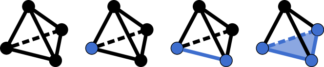
We consider the problem of inserting a topological offset of a potentially non-manifold triangle mesh that is embedded in an inversion-free manifold tetrahedral mesh; that is, we want a new tetrahedral mesh in which a subset of triangles represents the offset. By topological offset of a sub-mesh, we intuitively mean adding an infinitesimally thin layer around it. This is not to be confused with a finite offset, whose topology might change depending on its thickness (Figure 3, red curve).
We first briefly provide a formal definition of a continuous topological offset (Section 4.1), then provide a discrete counterpart, and describe an extension of the Marching Tetrahedra algorithm (Doi and Koide, 1991) to perform this insertion in tetrahedral meshes (Section 4.2).
4.1. Infinitesimal and Topological Offset
Consider a smooth, simple, manifold, closed surface with a single connected component, and bounded curvature embedded in a domain . A finite offset is the set of points at a distance from the surface,
where is the function returning the point of closest to the point . We can always find an such that the offset does not intersect the medial axis of , and thus, for such an , the function is bijective. By repeating the same construction for a non-smooth (possibly non-manifold) surface (Figure 3), an for which the function is bijective does not exist anymore since the medial axis extends to the sharp points of . However, there is still an such that all offsets computed with a distance smaller than have the same topology, are manifold, and are free of self-intersections. We call these offsets infinitesimal.
Theorem 1 (Infinitesimal Offsets).
For a triangular mesh , possibly non-manifold, we consider a 1-parameter family of offsets parametrized by a distance parameter , where is a surface-dependent constant. We call this family the infinitesimal offsets of . For a sufficiently small all offsets in the family is a simple and manifold surface homeomorphic to any other.
Proof.
The -offset of is the Minkowski sum of and the sphere of radius . The Minkowski sum surface is partitioned into patches which are subsets of spheres, cylinders and planes, associated with different simplex types of the mesh: spherical patches are parts of spheres centered at vertices, cylindrical patches belong to cylinders with axes along edges, and planar patches are parallel to faces. The connectivity between these patches is determined by adjacency and distances between simplices: two patches cannot be adjacent, if the distance between their simplices exceeds sphere radius. As is reduced, the number of simplices within distance is also reduced, until we reach the minimal number of connections, which is achieved when is less than half the minimal distance between any two simplices that are not adjacent. Further reducing does not change the number of potential intersections and thus does not change the topology of the offset.
The Minkowski sum is an infinite union of spheres: the union of two spheres is manifold, except if their intersection is a point not belonging to . To avoid this, we can always shrink . This process terminates, as the topology of the offset does not change for sufficiently small . Thus, there exists an such that the infinitesimal offset is manifold.
∎
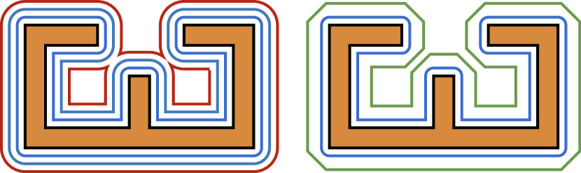
Since the infinitesimal offsets of a triangle mesh are all homeomorphic to each other, their topology is unique (Figure 3). This is not the case in general for finite offsets, where the offset topology might depend on the distance. We use this observation to define a Topological Offset (Figure 3), foregoing the use of distance in favor of a purely topological condition:
Definition 0 (Topological Offset).
A simple surface is a topological offset of a non-intersecting, simply connected (non-manifold) triangle mesh if and do not intersect and is homeomorphic to an infinitesimal offset of , i.e there exists a continuous and bijective function .
The function is a topological version of the closest point function used in the offset definition.
4.2. Discrete Topological Offset
We now extend the topological offset definition to a domain represented by a tetrahedral mesh and a triangle mesh embedded in . Eventually, we will generate the topological offset with a Marching-Tetrahedra-like algorithm, but in order to do so correctly, must be regularly embedded in .
Definition 0 (Regular Embedding).
The embedding of a simplicial triangle mesh in a simplicial tetrahedral mesh is regular if for any tetrahedron the intersection of and is either empty, a vertex, an edge, or a triangle.
Regularization of a Mesh Complex
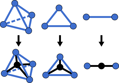
To ensure that is regularly embedded in , we propose an algorithm relying on iterating the split operation (Figure 4) to update . Algorithm 1 iterates over every tetrahedron , and checks if the boundary of is in (1). In that case, it splits the tetrahedron (2). It then iterates the same procedure on all triangles (2) and edges (3) that are not in . Note that a split to an edge or a face is propagated to the tetrahedra intersecting it.
Theorem 4 (Mesh Regularization).
is regularly embedded in the output of Algorithm 1.
Proof.
After the first loop of Algorithm 1 completes, no tetrahedron has four faces in . If a tetrahedron has three or two faces in , then there is a face or faces that have three edges in , and these faces will be split in the second loop. Therefore, after the first two loops, all tetrahedra have no more than one face in . Suppose a tetrahedron has a face and two or more edges not contained in this face in . Then there are triangles not in with three edges in that will be split in the second loop, i.e., there is no more than one edge in after the second loop. Thus after the first two loops, a tetrahedron may contain at most one face of and at most one edge not contained in this face, and some number of vertices of .
Similarly, in the last loop, if there is a face and an edge, or a face and a vertex, or an edge and a vertex, or two vertices, there will be always an edge not in with two vertices in that will be split in the third loop.
So we conclude that the output of the algorithm is regular.
∎
We note that Algorithm 1 is purely topological. The coordinates of the vertices of are never used, which makes our algorithm unconditionally robust. We note, however, that the computation of the vertex positions after a split might lead to inverted elements. However, we never encountered this problem in our large dataset (Section 7).
Construction of a Discrete Topological Offset
Given a triangle mesh regularly embedded in , we construct a topological offset by applying to each tetrahedron one of the unique rules in Figure 6. This procedure generates a topological offset, i.e., inserts a mesh , embedded in equipped with a continuous and bijective function mapping to .
5. Topological Offset Optimization
We now focus on a geometrical optimization of an offset surface embedded within a tetrahedral mesh. Our goal is to update its connectivity and vertex positions to be at a distance from the input.
Overview
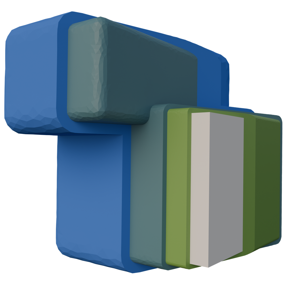
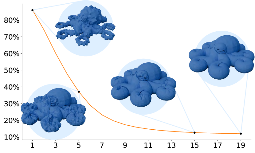
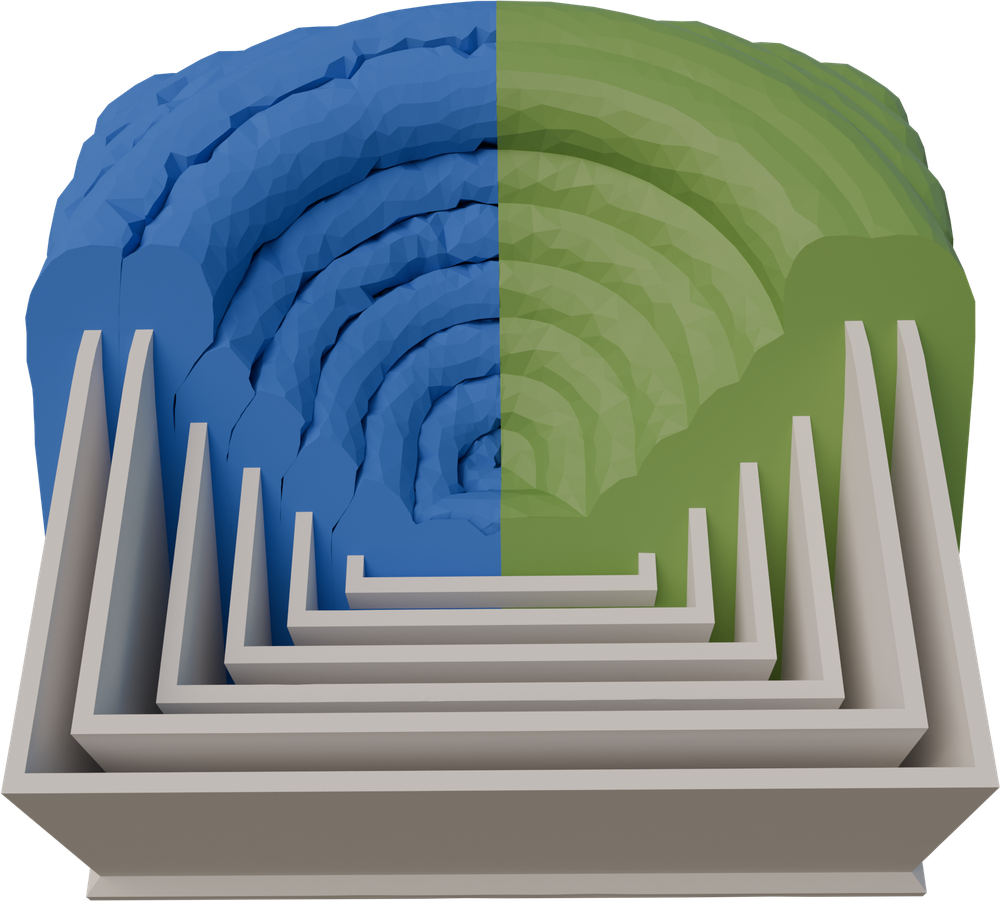
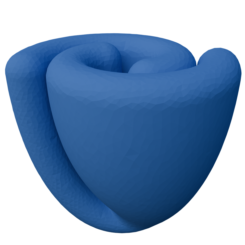
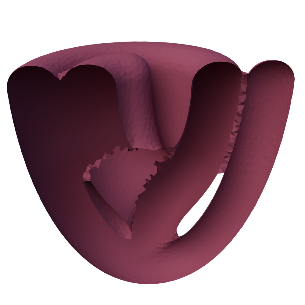
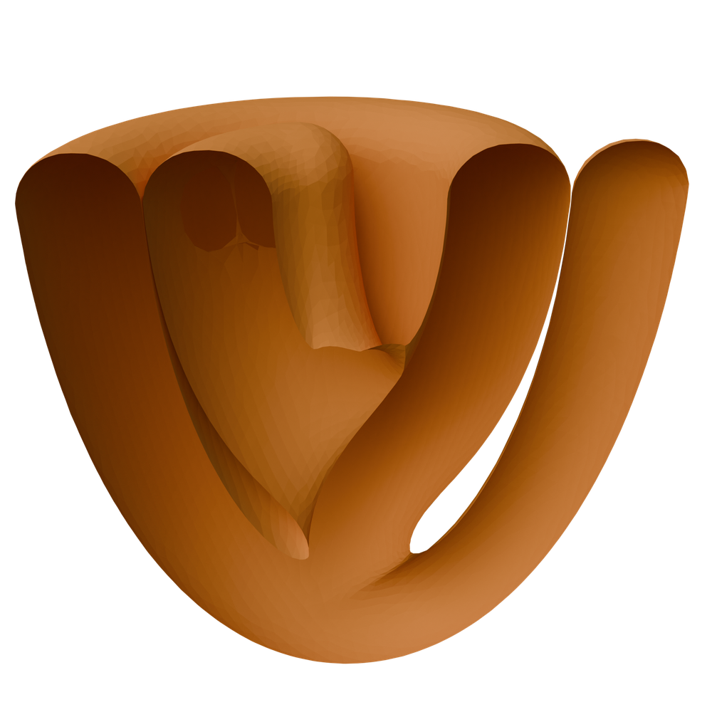
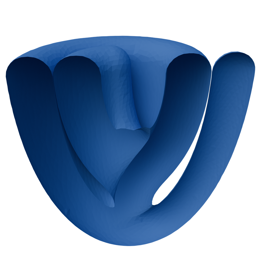
Our optimization algorithm is composed of three stages, which are repeated until convergence: (A) we update the sizing field, (B) we modify the offset mesh, improving its quality and moving its vertices to the desired distance from the input, and (C) we modify the background mesh, increasing its quality. In all iterations, the meshes are modified using a set of local operations, following (Botsch and Kobbelt, 2004): our algorithm iterates passes of splits, collapse, swaps, and vertex smoothing (Section 5.3). These operations are always performed on the volumetric mesh: if the algorithm tries to split an edge of the offset mesh, this operation is applied to the corresponding edge of the volumetric mesh or vice versa. In Figure 7) we show the evolution of our algorithm: starting from a valid topological offset, we slowly grow it to reach the desired distance. We note how the surface “squeezes” within itself without intersecting.
Relative distance %
Iterations
User parameters
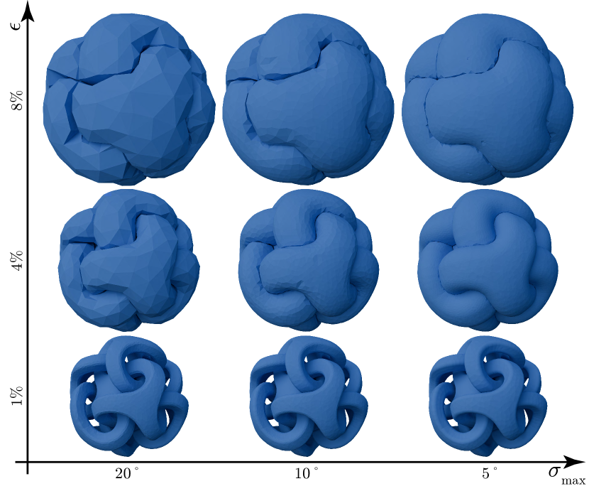
The user has two parameters to control the outcome of our method: the offset distance , and the maximum normal deviation . The latter controls how well the mesh should adapt to the offset curvature and is defined later in Section 5.1. The effect of the two parameters on the output is depicted in Figure 8.
Invariants
The operations are executed only if their effect on the mesh satisfies the following invariants: (I1) the input surface and the boundary are not modified, (I2) the orientation of all tetrahedra is preserved (tested using the exact predicate in (Shewchuk, 1996)) and (I3) the topology of the offset and input surface is preserved (Vivodtzev et al., 2010).
Theorem 1.
Let be a background mesh containing a surface and a surface . The mesh computed after performing any sequence of local operations satisfying the invariants I1, I2, I3 contains a new surface homeomorphic to that does not intersect .
Proof.
It follows from Theorem 1 that topological offsets are preserved by our mesh optimization.
Termination
The algorithm terminates when we reach relative convergence of the following metrics: mean triangle shape regularity, mean triangle normal deviation, and mean and maximum offset distance error. In the results in Section 7 we consider an offset as converged if all metrics do not change more than 1% in between two iterations.
5.1. Quality Metrics
Throughout the offset optimization, we use several quality metrics to test for convergence and to determine which operations to perform.
Definition 0 (Triangle Shape Regularity).
The shape regularity of a triangle as defined in (Bank and Smith, 1997) is its area multiplied by a normalization pre-factor of and divided by the sum of squared edge lengths.
The shape regularity is zero for a degenerate triangle and one for an equilateral one.
Definition 0 (Triangle Normal Deviation).
The normal deviation of a triangle is the maximum angle between the offset normal at the triangle center and the offset normal at any other point within the triangle, excluding its boundaries,
The offset normal can be computed for any point in space by finding the projection point on the offset and normalizing the vector from the point in space to its projection. We compute the normal deviation of a triangle by comparing with offset normals close to the vertices of the triangle, more precisely at the positions . This choice is motivated experimentally, as using more sampling points increases the running time with negligible improvements in quality.
Definition 0 (Offset Distance Error).
The offset distance error of a point on the offset mesh is the absolute value of the distance of that point to the surface minus the targeted offset distance .
5.2. Step A: Sizing Field Update
The edge split and collapse operations are driven by a sizing field that is defined on each edge of the offset mesh and is initialized with the current length of every edge.
In each update pass, if one of the incident triangles has a shape regularity below or a normal deviation above the user-defined maximum , the target length is divided by two. If both conditions are false, the target length is increased by . To keep the sizing field smooth, the target length of any edge is at maximum times the target length of any adjacent edge.
Additionally, we give a lower bound to the target length, defined as the chord length of a circle with radius and angle ,
An upper bound to the target length is not required.
5.3. Step B: Offset Optimization
Edge Split / Collapse.
Every edge that has a length greater than of its target length is split. The new vertex is positioned at the center of the edge. All edges that are shorter than of their target length are collapsed. We perform half-edge collapses. While there are no extra conditions for splits, a collapse is only performed if the user-defined maximum normal deviation is not exceeded. Both operations are scheduled according to the current edge length but for splits, long edges are prioritized while, for collapse, the short ones are considered first.
Edge Swap.
Edges are swapped if the operation increases the minimal triangle shape regularity of the two adjacent triangles. The swap is not performed if the normal deviation before the operation is below the user-defined maximum and would be above afterward. Long edges are prioritized in the swap operation.
Vertex Relocation.
We use the vertex relocation method that was described in (Zint et al., 2023). If the computed position would cause a tetrahedron from the embedding to be flipped, we perform a binary search along the way to the computed position to find a valid position. If no valid position can be found, we do not move the vertex.
Vertices that could be moved to the computed optimal position are flagged as converged. If a triangle contains only converged vertices, its shape regularity is above and its normal deviation is below the user-defined maximum, we flag the triangle as converged. If all triangles incident to a simplex are converged, that simplex is not considered for any operation. For example, we do not relocate a vertex if all its incident triangles are converged. This helps to reduce runtime.
5.4. Step C: Embedding Optimization
We use the optimization scheme that was presented in (Hu et al., 2018) with two minor modifications (in addition to the aforementioned invariants) to make it more efficient, as we are not interested in obtaining a mesh of very high quality: we only want the mesh to not hinder the movement of the offset. The tetrahedral mesh is merely a scaffold for our embedded surfaces. We do not improve its mesh quality for its own sake, but to make sure that it is not hindering the offset optimization.
First, we trigger the update of the sizing field if the tetrahedron AMIPS energy is above 100 (instead of 8) and limit the target edge length to three times the length of any adjacent edge. Second, we only optimize the two-ring neighbourhood of tetrahedron with AMIPS above 100.
6. Extensions
6.1. Manifold Extraction
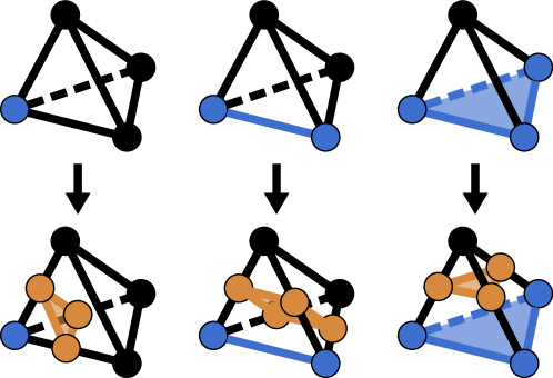
A common way to remove non-manifold vertices is to duplicate them and displace them in the opposite normal direction. While this method is simple, it comes with several drawbacks. First, it is not guaranteed that a valid normal direction always exists, and therefore it can fail for certain scenarios. Second, if the mesh was embedded in a volumetric mesh, the region around the duplicated vertex needs to be remeshed.
![[Uncaptioned image]](/html/2407.07725/assets/x7.png)
Using our method, we can safely remove non-manifold regions from a mesh by constructing a topological offset (see inset). First, we detect all non-manifold simplices and consider them as the input for our topological offset, that is, we build an offset around them. Second, we remove all simplices from the mesh that are within the offset region; thus the mesh becomes manifold. If the input mesh is water-tight, we use the inside/outside information to close the mesh along the boundary of the offset region.
Our algorithm is guaranteed to generate manifold meshes and to keep the embedding valid; however, it might add unnecessary vertices to the surface. To mitigate this effect, we perform a “clean-up” after the insertion of the offset region: we try to collapse edges that are within the region of the same non-manifold vertex. We only perform collapses that maintain a valid embedding (i.e., do not cause any inverted tetrahedron).
Finally, we try to push all remaining vertices to a user-defined offset distance. If the desired distance would cause tetrahedral inversions, we use a binary search to find a valid position. If we cannot find a valid position, we keep the vertex where it is.
This method has similarities to one of the methods presented in (Attene et al., 2009). However, our method does not rely on an offset distance and maintains a valid embedding. Additionally, as our topological offsets do not require any geometrical parameters, it is guaranteed to succeed in rational numbers.
6.2. Finite and Layered Offsets
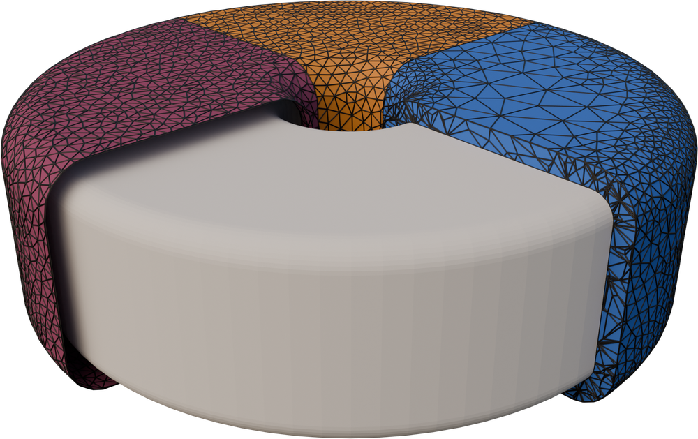
Extending our topological offset to a finite (or to multiple finite offsets) only requires a simple modification in the topological offset initialization. We tag all tetrahedra that are within offset distance. When we initialize the topological offset, we consider those tetrahedra as part of the input. Finally, we optimize the offset shape in the exact same way as before, Figure 9. If we want to construct multiple offset layers, we consider all previously generated offsets as part of the input in the topological offset initialization, which guarantees that the offsets are strictly enclosing each other.
7. Results and Applications
7.1. Large scale study
We run our method on the entire Thingi10k dataset (Zhou and Jacobson, 2016) that was pre-processed with TetWild (Hu et al., 2018) with default settings to generate the required embedding on cluster nodes with a Xeon E5-2690 v2 @ 3.00GHz. We use the inside/outside tags to create a one-sided offset. 232 meshes did not contain any inside tag or a tag was on the boundary, which our method does not support. This left 9768 meshes in our experiments. We cap the runtime at 24 hours and we stop the optimization after 10 iterations or when the convergence criteria from Section 5 are met.
Time (s)
Number of offset surface triangles
Number of embedding tetrahedra
Relative distance
Normal deviation
Topological Offsets
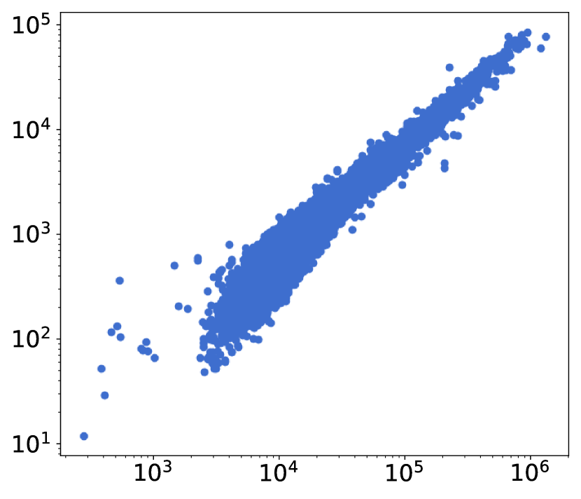
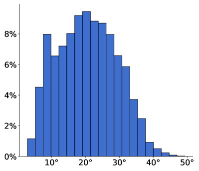
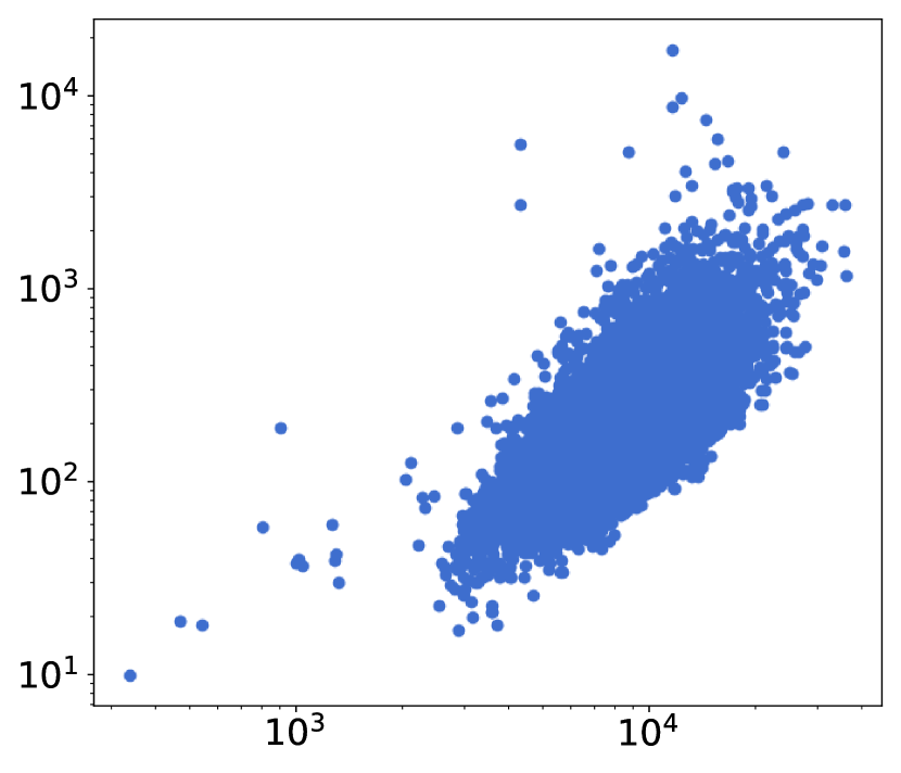
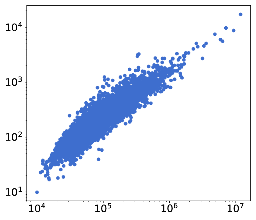
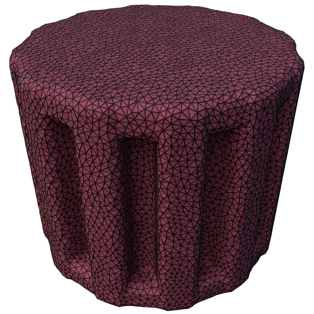
Our method is guaranteed to produce manifold and intersection-free topological offsets in rational numbers. While theoretically, we might lose the geometrical guarantees when using floating point numbers, we empirically confirm that all our results are valid. We compute topological offsets for the Thingi10k dataset with a target distance relative to the bounding box size and a maximum normal deviation . Figure 10, shows how the runtime of our algorithm correlates to the complexity of the output meshes: an output mesh with a thousand tetrahedra takes around 2 minutes, while a mesh with a million tetrahedra takes about 3 hours. Half of the models finish within 22 minutes, and only models take more than the maximum allocated hours. Figure 14 shows a model with a surface containing small details where our method struggles to converge; it runs out of the 10 iterations before fully converged. Even in that case, the result looks reasonable. Figure 11 shows that the topological offset can not always reach the target distance and maximum normal deviation . This is the case because there is no space for the offset to move and it is “pushing” against itself, Figure 12.
Time (s)
Number of offset surface triangles
Number of embedding tetrahedra
Relative distance
Normal deviation
Finite Offsets
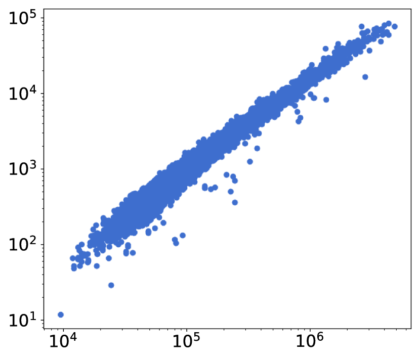
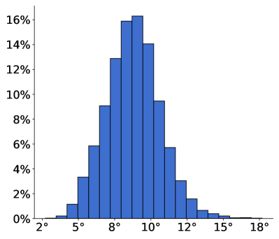
We compute finite offsets for the Thingi10k dataset with the same parameters as the topological offsets, i.e., and . Figure 13 shows the runtime: generating a finite offset is much faster, with the fastest model taking about 10 seconds and the slowest about 5 hours, since the optimization is less constrained by colliding offsets. Two thirds of the models finish within 5 minutes. As explained in Section 5 there is no guarantee that the desired distance is achieved. Despite that, Figure 15 shows that all models are within 5% of the target distance and that the offset surface normal matches up to . This contrasts the topological offset (Figure 11) as the offset does not collide with itself and therefore reaches the desired distance.
7.2. Comparison
We compare our method with Feature-Preserving Offsets (FPO) (Zint et al., 2023), and 3D Alpha Wrapping in CGAL (Alliez et al., 2024). The parameters for all methods were chosen such that all methods produce a similar offset. On simple models, like the one in Figure 16, all three methods perform well. However, our method requires significantly more time to produce similar results. Alpha Wrapping and FPO finish in less than one and 13 seconds respectively, while our method needs about 8 minutes. This overhead is caused by the tetrahedral embedding that needs to be updated. Our method returns a tetrahedral mesh in which the input and offset are embedded, while the others only generate surfaces.
Our method is using a sizing field to be adaptive to the offset curvature. Flat regions are not unnecessarily refined (Figure 17) while the mesh is denser in regions with high curvature compared to the meshes from the other methods.
An extreme challenge for offset methods is when two offsets are almost colliding. Alpha Wrapping and FPO are both struggling with the scenario in Figure 18. Alpha Wrapping cannot enter the thin area in between the two offsets. FPO produces a good-looking result from the outside but generates self-intersections on the interior. Our method produces the desired outcome and is free of self-intersections.
Note that Alpha Wrapping is not an offsetting method and, therefore, does not claim to be feature-preserving or topologically correct. We chose this method to compare against because it is, to our knowledge, the only one that comes with similar guarantees to ours.
7.3. Extensions
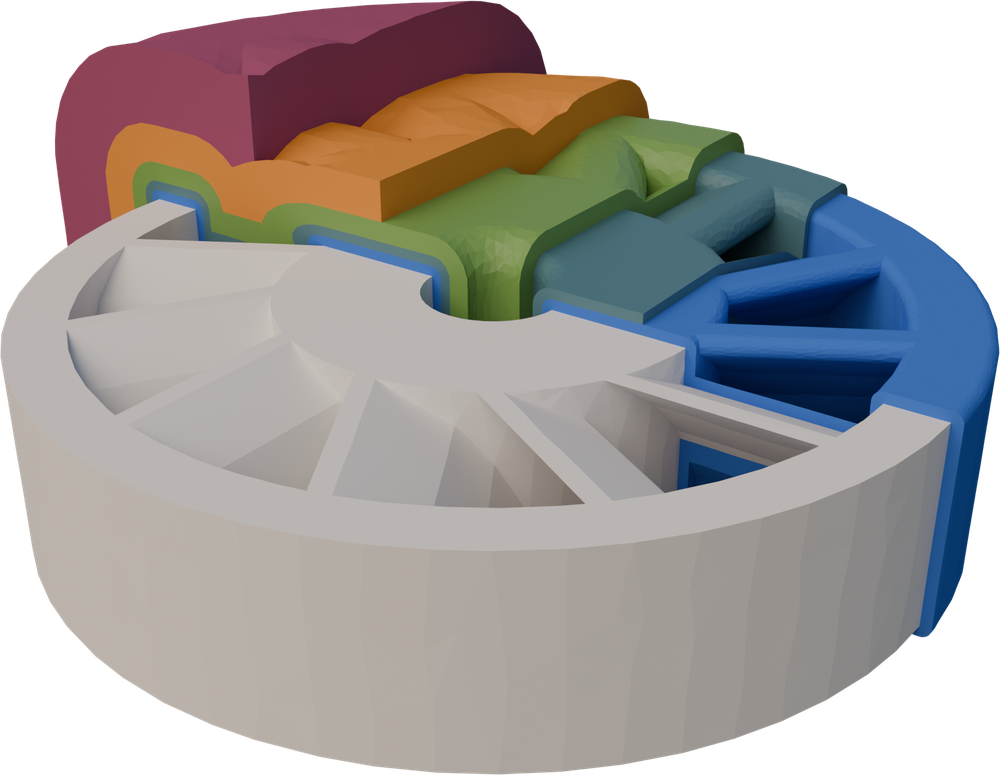
Layered Offsets
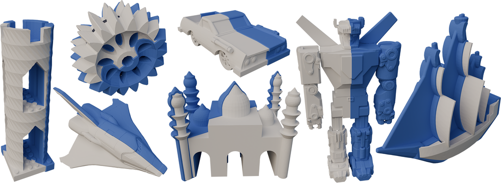
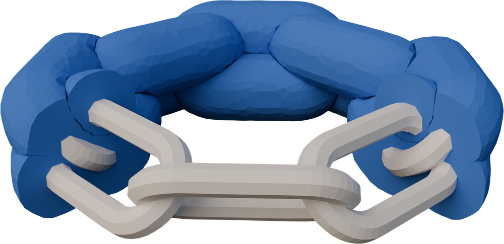
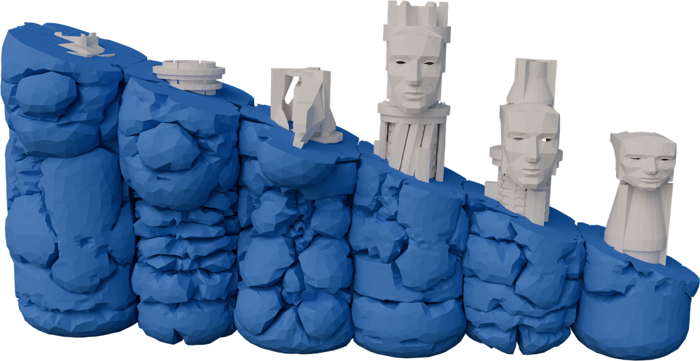
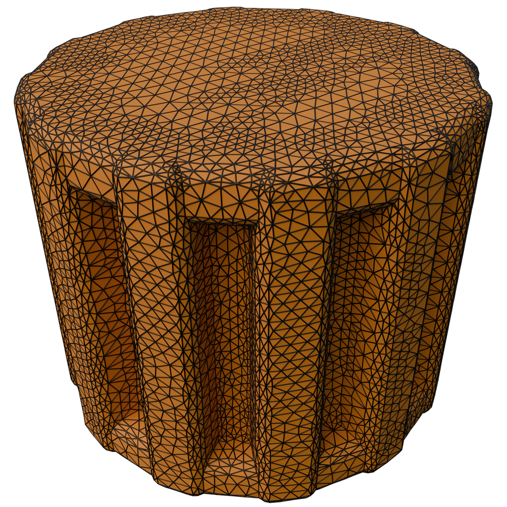
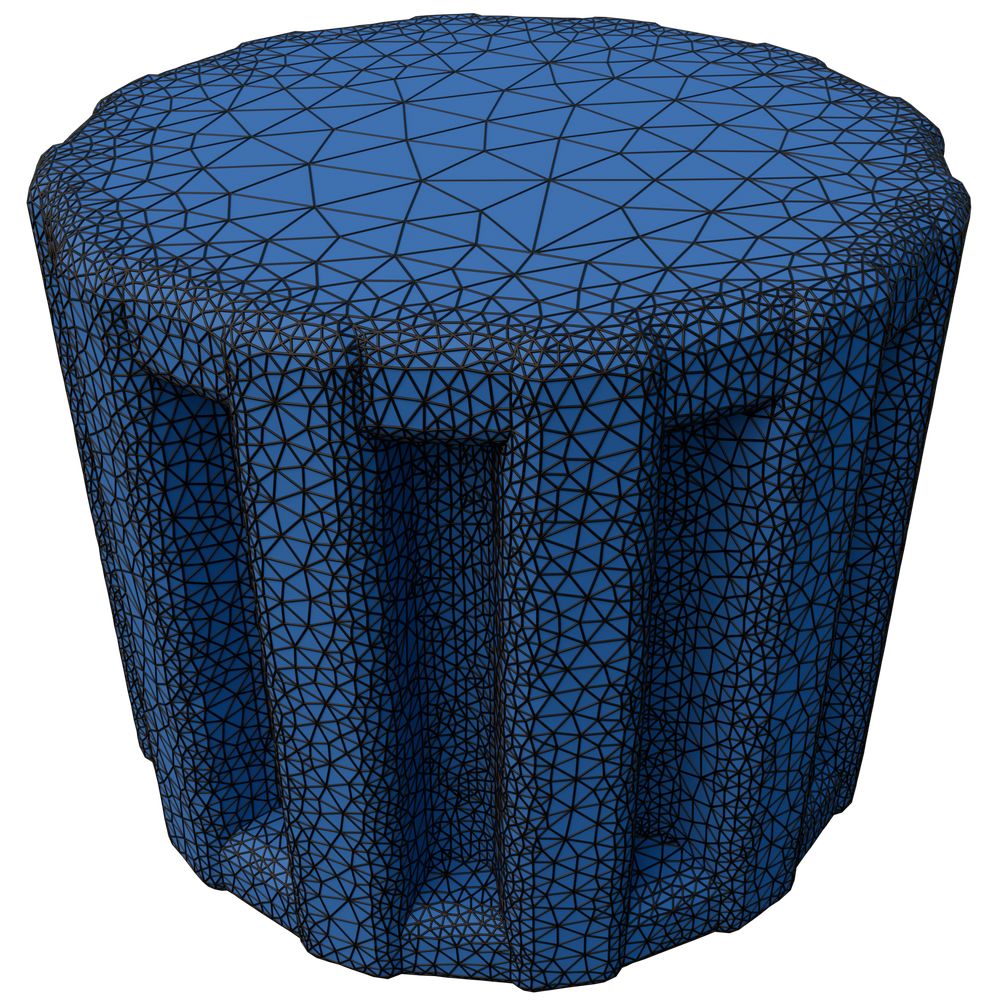
As mentioned in Section 6, we can use our method to generate layered offsets. In Figure 19, we show a gear model with four different offsets at different distances from the input. All offsets are not intersecting with each other or the input surface, and are guaranteed to be manifold.
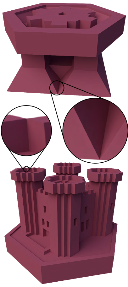
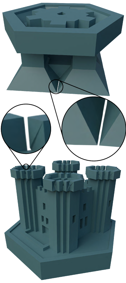
Removal of Non-Manifold Regions
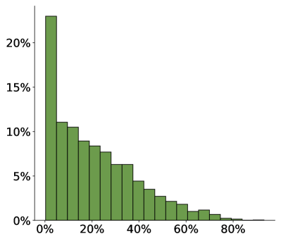
We run the non-manifold removal algorithm described in Section 6 on the 1053 models from TetWild whose surfaces are non-manifold. The algorithm succeeds for all models, i.e., there are no issues with floating point inaccuracy, no models contain inverted elements, and all surfaces do not intersect. In Figure 20, we summarize the results: for 970 out of the 1053 models (92%), our method introduces less than 10% more triangles on the surface. There are only 4 models, less than 0.4%, where the element count doubles since almost all surface vertices and edges are non-manifold. Different from previous work, our method always maintains a valid embedding. Figure 21 shows how non-manifold vertices and edges are successfully removed from two models.
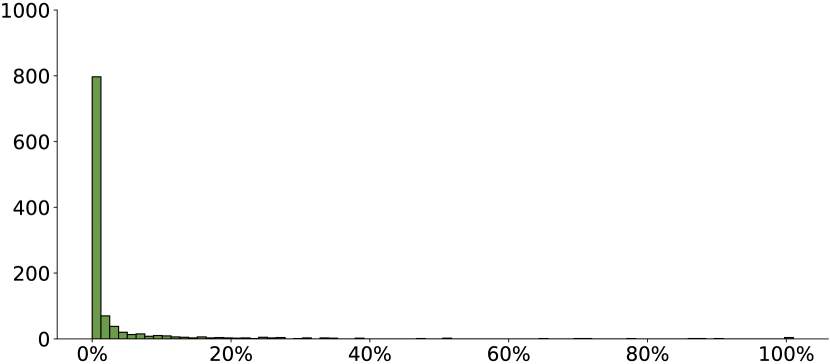
Number of models
Relative increase of the number of triangles
Non-manifold input
Manifold output
8. Concluding Remarks
We introduced a theoretical framework and an algorithm for computing topological offsets and demonstrated their relevance in a wide range of graphics applications.
While computationally more expensive than competing finite offset methods, our algorithm generates the unique topology of an infinitesimal offset, and guarantees to produce self-intersection-free offsets that are strictly enclosing the input. We use these guarantees to extend our construction to multiple offsets (topological or finite) that inherit the same guarantees and therefore are strictly enclosing each other.
Exploring the use of this approach to create layered offsets with exponentially increasing thickness and their use for fluid simulation is an exciting avenue for future work. Additionally, we plan to explore parallel or distributed mesh optimization methods to reduce the running time difference compared to other offset methods.
References
- (1)
- Alliez et al. (2024) Pierre Alliez, David Cohen-Steiner, Michael Hemmer, Cédric Portaneri, and Mael Rouxel-Labbé. 2024. 3D Alpha Wrapping. In CGAL User and Reference Manual (5.6.1 ed.). CGAL Editorial Board. https://doc.cgal.org/5.6.1/Manual/packages.html#PkgAlphaWrap3
- Attene et al. (2009) Marco Attene, Daniela Giorgi, Massimo Ferri, and Bianca Falcidieno. 2009. On converting sets of tetrahedra to combinatorial and PL manifolds. Computer Aided Geometric Design 26, 8 (2009), 850–864. https://doi.org/10.1016/j.cagd.2009.06.002
- Aubry et al. (2017) R Aubry, S Dey, EL Mestreau, and BK Karamete. 2017. Boundary layer mesh generation on arbitrary geometries. Internat. J. Numer. Methods Engrg. 112, 2 (2017), 157–173.
- Bank and Smith (1997) Randolph E Bank and R Kent Smith. 1997. Mesh smoothing using a posteriori error estimates. SIAM J. Numer. Anal. 34, 3 (1997), 979–997.
- Boada et al. (2008) Imma Boada, Narcís Coll, Narcís Madern, and J Antoni Sellares. 2008. Approximations of 2d and 3d generalized voronoi diagrams. International Journal of Computer Mathematics 85, 7 (2008), 1003–1022.
- Botsch and Kobbelt (2004) Mario Botsch and Leif Kobbelt. 2004. A remeshing approach to multiresolution modeling. In Proceedings of the 2004 Eurographics/ACM SIGGRAPH symposium on Geometry processing. 185–192.
- Brodersen et al. (2008) Anders Brodersen, Ken Museth, Serban Porumbescu, and Brian Budge. 2008. Geometric Texturing Using Level Sets. IEEE Transactions on Visualization and Computer Graphics 14, 2 (2008), 277–288. https://doi.org/10.1109/TVCG.2007.70408
- Campen and Kobbelt (2010a) Marcel Campen and Leif Kobbelt. 2010a. Exact and robust (self-) intersections for polygonal meshes. In Computer Graphics Forum, Vol. 29. Wiley Online Library, 397–406.
- Campen and Kobbelt (2010b) Marcel Campen and Leif Kobbelt. 2010b. Polygonal boundary evaluation of Minkowski sums and swept volumes. In Computer Graphics Forum, Vol. 29. Wiley Online Library, 1613–1622.
- Chen et al. (2019) Zhen Chen, Daniele Panozzo, and Jeremie Dumas. 2019. Half-space power diagrams and discrete surface offsets. IEEE Transactions on Visualization and Computer Graphics 26, 10 (2019), 2970–2981.
- Diazzi et al. (2023) Lorenzo Diazzi, Daniele Panozzo, Amir Vaxman, and Marco Attene. 2023. Constrained Delaunay Tetrahedrization: A Robust and Practical Approach. ACM Transactions on Graphics 42, 6 (Dec. 2023), 1–15. https://doi.org/10.1145/3618352
- Doi and Koide (1991) A. Doi and A. Koide. 1991. An Efficient Method of Triangulating Equi-valued Surfaces by Using Tetrahedral Cells. IEICE Trans. 74, 1 (1991).
- Faraj et al. (2016) Noura Faraj, Jean-Marc Thiery, and Tamy Boubekeur. 2016. Multi-Material Adaptive Volume Remesher. Computer and Graphics Journal (proc. Shape Modeling International 2016) 58 (2016), 150–160.
- Garimella and Shephard (2000) Rao V. Garimella and Mark S. Shephard. 2000. Boundary layer mesh generation for viscous flow simulations. Internat. J. Numer. Methods Engrg. 49, 1–2 (2000), 193–218. https://doi.org/10.1002/1097-0207(20000910/20)49:1/2<193::aid-nme929>3.0.co;2-r
- Guo et al. (2024) Jia-Peng Guo, Wen-Xiang Zhang, Chunyang Ye, and Xiao-Ming Fu. 2024. Robust Coarse Cage Construction With Small Approximation Errors. IEEE Transactions on Visualization and Computer Graphics 30, 7 (2024), 4234–4245. https://doi.org/10.1109/TVCG.2023.3255207
- Hemmer et al. (2010) Michael Hemmer, Ophir Setter, and Dan Halperin. 2010. Constructing the Exact Voronoi Diagram of Arbitrary Lines in Three-Dimensional Space. In Algorithms – ESA 2010, Mark de Berg and Ulrich Meyer (Eds.). Springer Berlin Heidelberg, Berlin, Heidelberg, 398–409.
- Hu et al. (2018) Yixin Hu, Qingnan Zhou, Xifeng Gao, Alec Jacobson, Denis Zorin, and Daniele Panozzo. 2018. Tetrahedral meshing in the wild. ACM Trans. Graph. 37, 4 (2018), 60–1.
- Huang et al. (2020) Jingwei Huang, Yichao Zhou, and Leonidas Guibas. 2020. ManifoldPlus: A Robust and Scalable Watertight Manifold Surface Generation Method for Triangle Soups. arXiv preprint arXiv:2005.11621 (2020).
- Jiang et al. (2020) Zhongshi Jiang, Teseo Schneider, Denis Zorin, and Daniele Panozzo. 2020. Bijective projection in a shell. ACM Transactions on Graphics 39, 6 (Nov. 2020), 1–18. https://doi.org/10.1145/3414685.3417769
- Ju et al. (2002) Tao Ju, Frank Losasso, Scott Schaefer, and Joe Warren. 2002. Dual contouring of hermite data. In Proceedings of the 29th annual conference on Computer graphics and interactive techniques. 339–346.
- Juretić and Putz (2011) Franjo Juretić and Norbert Putz. 2011. A Surface-Wrapping Algorithm with Hole Detection Based on the Heat Diffusion Equation. Springer Berlin Heidelberg, 405–418. https://doi.org/10.1007/978-3-642-24734-7_22
- Karavelas (2022) Menelaos Karavelas. 2022. 2D Segment Delaunay Graphs. In CGAL User and Reference Manual (5.5.1 ed.). CGAL Editorial Board. https://doc.cgal.org/5.5.1/Manual/packages.html#PkgSegmentDelaunayGraph2
- Kobbelt et al. (1999) Leif P. Kobbelt, Jens Vorsatz, Ulf Labsik, and Hans‐Peter Seidel. 1999. A Shrink Wrapping Approach to Remeshing Polygonal Surfaces. Computer Graphics Forum 18, 3 (Sept. 1999), 119–130. https://doi.org/10.1111/1467-8659.00333
- Lee et al. (2009) Y. K. Lee, Chin K. Lim, Hamid Ghazialam, Harsh Vardhan, and Erling Eklund. 2009. Surface mesh generation for dirty geometries by the Cartesian shrink-wrapping technique. Engineering with Computers 26, 4 (Dec. 2009), 377–390. https://doi.org/10.1007/s00366-009-0171-0
- Lipman (2014) Yaron Lipman. 2014. Bijective Mappings of Meshes with Boundary and the Degree in Mesh Processing. SIAM Journal on Imaging Sciences 7, 2 (Jan. 2014), 1263–1283. https://doi.org/10.1137/130939754
- Liu and Wang (2010) Shengjun Liu and Charlie CL Wang. 2010. Fast intersection-free offset surface generation from freeform models with triangular meshes. IEEE Transactions on Automation Science and Engineering 8, 2 (2010), 347–360.
- Lorensen and Cline (1987) William E Lorensen and Harvey E Cline. 1987. Marching cubes: A high resolution 3D surface construction algorithm. ACM siggraph computer graphics 21, 4 (1987), 163–169.
- Loseille and Löhner (2013) Adrien Loseille and Rainald Löhner. 2013. Robust boundary layer mesh generation. In Proceedings of the 21st International Meshing Roundtable. Springer, 493–511.
- Martineau et al. (2016) David Martineau, Jeremy Gould, and J. Papper. 2016. AN INTEGRATED FRAMEWORK FOR WRAPPING AND MESH GENERATION OF COMPLEX GEOMETRIES. https://api.semanticscholar.org/CorpusID:56019523
- Martinez et al. (2015) Jonas Martinez, Samuel Hornus, Frédéric Claux, and Sylvain Lefebvre. 2015. Chained segment offsetting for ray-based solid representations. Computers & Graphics 46 (2015), 36–47.
- Meng et al. (2018) Wenlong Meng, Shuangmin Chen, Zhenyu Shu, Shi-Qing Xin, Hongbo Fu, and Changhe Tu. 2018. Efficiently computing feature-aligned and high-quality polygonal offset surfaces. Computers & Graphics 70 (2018), 62–70.
- Misztal and Bærentzen (2012) Marek Krzysztof Misztal and Jakob Andreas Bærentzen. 2012. Topology-adaptive interface tracking using the deformable simplicial complex. ACM Trans. Graph. 31, 3, Article 24 (jun 2012), 12 pages. https://doi.org/10.1145/2167076.2167082
- Pavić and Kobbelt (2008) Darko Pavić and Leif Kobbelt. 2008. High-resolution volumetric computation of offset surfaces with feature preservation. In Computer Graphics Forum, Vol. 27. Wiley Online Library, 165–174.
- Portaneri et al. (2022) Cédric Portaneri, Mael Rouxel-Labbé, Michael Hemmer, David Cohen-Steiner, and Pierre Alliez. 2022. Alpha wrapping with an offset. ACM Transactions on Graphics 41, 4 (July 2022), 1–22. https://doi.org/10.1145/3528223.3530152
- Porumbescu et al. (2005) Serban D. Porumbescu, Brian Budge, Louis Feng, and Kenneth I. Joy. 2005. Shell maps. ACM Trans. Graph. 24, 3 (jul 2005), 626–633. https://doi.org/10.1145/1073204.1073239
- Qu et al. (2004) Huamin Qu, Nan Zhang, Ran Shao, Arie Kaufman, and Klaus Mueller. 2004. Feature preserving distance fields. In 2004 IEEE Symposium on Volume Visualization and Graphics. IEEE, 39–46.
- Sacht et al. (2015) Leonardo Sacht, Etienne Vouga, and Alec Jacobson. 2015. Nested cages. ACM Transactions on Graphics 34, 6 (Nov. 2015), 1–14. https://doi.org/10.1145/2816795.2818093
- Shewchuk (1996) Johnathan Richard Shewchuk. 1996. Robust adaptive floating-point geometric predicates. In Proceedings of the Twelfth Annual Symposium on Computational Geometry (Philadelphia, Pennsylvania, USA) (SCG ’96). Association for Computing Machinery, New York, NY, USA, 141–150. https://doi.org/10.1145/237218.237337
- Stuart et al. (2013) David A. Stuart, Joshua A. Levine, Ben Jones, and Adam W. Bargteil. 2013. Automatic Construction of Coarse, High-Quality Tetrahedralizations that Enclose and Approximate Surfaces for Animation. In Proceedings of Motion on Games (MIG ’13). ACM. https://doi.org/10.1145/2522628.2522648
- Suriyababu et al. (2023) Vijai Kumar Suriyababu, Cornelis Vuik, and Matthias Möller. 2023. Towards a High Quality Shrink Wrap Mesh Generation Algorithm Using Mathematical Morphology. Computer-Aided Design 164 (Nov. 2023), 103608. https://doi.org/10.1016/j.cad.2023.103608
- Thomas et al. (2011) Dilip Mathew Thomas, Vijay Natarajan, and Georges-Pierre Bonneau. 2011. Link Conditions for Simplifying Meshes with Embedded Structures. IEEE Transactions on Visualization and Computer Graphics 17, 7 (July 2011), 1007–1019. https://doi.org/10.1109/tvcg.2010.90
- Tournois et al. (2023) Jane Tournois, Noura Faraj, Jean-Marc Thiery, and Tamy Boubekeur. 2023. Tetrahedral Remeshing. In CGAL User and Reference Manual (5.6 ed.). CGAL Editorial Board. https://doc.cgal.org/5.6/Manual/packages.html#PkgTetrahedralRemeshing
- Varadhan and Manocha (2004) Gokul Varadhan and Dinesh Manocha. 2004. Accurate Minkowski sum approximation of polyhedral models. In 12th Pacific Conference on Computer Graphics and Applications, 2004. PG 2004. Proceedings. IEEE, 392–401.
- Vivodtzev et al. (2010) Fabien Vivodtzev, Georges-Pierre Bonneau, Stefanie Hahmann, and Hans Hagen. 2010. Substructure Topology Preserving Simplification of Tetrahedral Meshes. Springer Berlin Heidelberg, 55–66. https://doi.org/10.1007/978-3-642-15014-2_5
- Wang et al. (2020) Bolun Wang, Teseo Schneider, Yixin Hu, Marco Attene, and Daniele Panozzo. 2020. Exact and efficient polyhedral envelope containment check. ACM Transactions on Graphics 39, 4 (Aug. 2020). https://doi.org/10.1145/3386569.3392426
- Wang and Manocha (2013) Charlie CL Wang and Dinesh Manocha. 2013. GPU-based offset surface computation using point samples. Computer-Aided Design 45, 2 (2013), 321–330.
- Yap et al. (2012) Chee K Yap, Vikram Sharma, and Jyh-Ming Lien. 2012. Towards exact numerical Voronoi diagrams. In 2012 Ninth International Symposium on Voronoi Diagrams in Science and Engineering. IEEE, 2–16.
- Zhou and Jacobson (2016) Qingnan Zhou and Alec Jacobson. 2016. Thingi10K: A Dataset of 10,000 3D-Printing Models. arXiv preprint arXiv:1605.04797 (2016).
- Zint et al. (2023) Daniel Zint, Nissim Maruani, Mael Rouxel-Labbé, and Pierre Alliez. 2023. Feature-Preserving Offset Mesh Generation from Topology-Adapted Octrees. Computer Graphics Forum 42, 5 (2023), 12.