Closed-loop measurements in an atom interferometer gyroscope
with velocity-dependent phase-dispersion compensation
Abstract
Atom interferometer-based gyroscopes are expected to have a wide range of applications due to their high sensitivity. However, their dynamic range is limited by dephasing caused by velocity-dependent Sagnac phase shift in combination with the velocity distribution of the atoms, restricting measurements of large angular velocities. In this study, we present a method for restoring the contrast deterioration in rotation rate measurements with interferometer gyroscopes using atomic beams. Our findings confirm that by introducing the pseudo-rotation effect with appropriate two-photon detunings for Raman lights in the interferometer, it is possible to effectively cancel the rotation of all atoms in the velocity distribution of the beam. Consequently, the contrast is unaffected by the rotation. Furthermore, we applied this method to an interferometer gyroscope with counterpropagating atomic beams sharing the same Raman lights. We also found that the rotation rate of the system can be estimated through the detunings points where the phase difference between the two interferometers is zero. This approach ensures that the scale factor of the atom interferometer gyroscope is independent of the velocity fluctuation of the atomic beam. We demonstrate our technique using the interferometer gyroscope of thermal atomic beams of rubidium-87, achieving a measurement of rotation rate of even with an acceleration of 0.68 on a three-axis rotation table. This simple and robust dispersion compensation method with Raman light detuning benefits dynamic rotation-rate measurements in field applications such as the inertial navigation of vehicles.
I Introduction
In the three decades following its inception [1, 2], light-pulse atom interferometry has been actively researched as a sensing tool across many fields for measuring acceleration [3, 4], rotation rate [5, 6, 7, 8, 9], gravity [10, 11, 12], gravity gradient [13, 14], fundamental constants [15, 16], gravitational waves [17, 18, 19, 20], dark matter and dark force [20, 21]. In recent years, the performance of atom-interferometry-based inertial sensors has reached the level of field applications [22, 23, 24, 25, 26] owing to their improved sensitivity and accuracy. Among various applications, these sensors are notably expected to be employed in inertial navigation [27]. Inertial navigation is a method of estimating the position of an individual without relying on external references such as the global positioning system, which requires highly accurate angular rates and acceleration sensors. The accuracy of conventional inertial sensors, such as fiber optic gyroscopes (FOGs), has significantly improved in recent years [28, 29, 30]; however, the expected high sensitivity that atom interferometry would bring is essential for highly accurate inertial navigation [31, 32, 33].
For inertial navigation, the sensors should possess a high dynamic range of measurement, which is a primary research obstacle in employing atom interferometry in inertial sensors. In atom interferometry, angular velocity and acceleration cause shifts in the interference phase (so-called “Sagnac effect” for angular velocity [34, 35, 36]). The magnitude of these phase shifts depends on the velocity of the atoms. Owing to the velocity distribution of atoms, the phase shift due to the angular velocity or acceleration will also have a dispersion, resulting in signal loss when the average phase shift is observed. This effect becomes more intense as the width of the velocity distribution increases relative to the average speed of the atoms. One of the most successful methods for extending the dynamic range is to compress the longitudinal velocity of an atomic beam using laser cooling techniques. Kwolek et al. [37] produced an atomic beam with a narrow velocity distribution by extracting laser-cooled and trapped atoms as a continuous beam. They irradiated these atoms with lights detuned to correspond to the Doppler shift associated with the desired longitudinal velocity. de Castanet et al. [38] developed an alternative method for an inertial sensor using a cold-atom interferometer. They extended the dynamic measurement range by mechanically changing the direction of the laser light within the interferometer to counteract the effects of the applied acceleration and angular velocity measured using classical sensors. Although these methods are helpful, building them compactly is challenging because they require additional optics and light sources for laser cooling, as well as additional mechanical structures. Moreover, these additional components may introduce instability. In addition, achieving high accuracy in measuring and controlling the velocity of atoms is challenging. Therefore, velocity instability affects the stability of angular velocity measurements, particularly because the scale factor is dependent on it.
In this study, we demonstrate a closed-loop phase-dispersion compensation method to enhance the dynamic range of inertial sensors using a spatial-domain interferometer. Importantly, this enhancement is achieved without adding any new elements. This is accomplished by simply adjusting the frequency of the lights that compose the interferometer. Our method involves phase compensation that is dependent on the time-of-flight of the atoms between lights, that is, the velocity of the atoms. The concept of velocity-dependent phase dispersion compensation was proposed and demonstrated through the precise measurement of the electric polarizability of a sodium atom [39]. The phase shift owing to the interaction between the atom and the electric field was compensated using a phase shifter. This phase shifter creates electric field gradients, introducing a phase shift that is inversely proportional to the velocity of the atoms. Different types of phase shifters have been demonstrated in previous gyroscope research, where the detuning of Raman lights that construct atom interferometers, was employed in a measurement of Earth rotation [5]. Additionally, phase shifters utilizing optical prism pairs have been proposed for use in electrical polarizability measurements [40].
Gustavon et al. [5] reported a measurement that compensates using the Sagnac effect by Raman phase shifters; however, further detailed study on this is still needed. Here, we present a detailed calculation of the velocity-dependent phase dispersion compensation for continuously measuring the rotation rate of a system using dual-beam atom interferometers. In addition, we demonstrate our method using an atom interferometer gyroscope (AIG) with dual thermal atomic beams mounted on a three-axis rotation table. Our method exhibited promising results even when acceleration was applied, and the velocity of the atomic beam changed during the time-of-flight. This study proves that the closed-loop operation of the AIG can be used to extend the dynamic range of rotation rate measurements.
II Rotation compensation with the frequency detunings of Raman lights
Let us consider a – – Mach–Zehnder-type atom interferometer using Raman transitions. Here, we provide an overview of the Raman transitions and interferometers (details can be found in references [41, 5]). Figure 1 shows the space–time diagram of the single-beam interferometer.
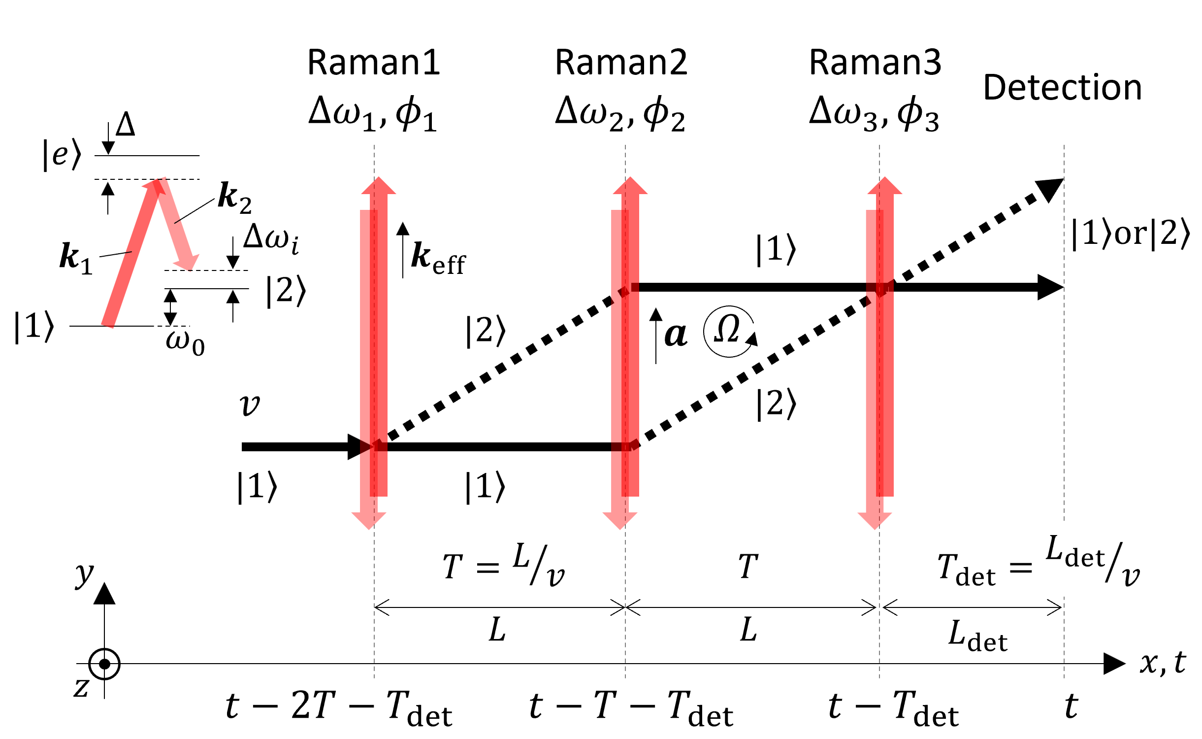
An atom in the ground state and state , whose energy is higher than ( is the Planck constant), travels at a velocity . When the atom is irradiated with a pair of counter-propagating laser beams, a two-photon Raman transition between and occurs. Atoms transitioning to the state through the Raman transition receive recoil momentum from lights, where and are the wave vectors of the pair of laser lights. This causes the atoms in the two states to travel different paths. The wavelengths of the beams are sufficiently detuned by from the excited state to avoid an actual excitation, and their frequency difference is tuned to , where is a recoil frequency and is the mass of the atom. An interferometer can be constructed by setting the two-photon Rabi frequency determined by the intensity of the Raman light such that the first, second, and final Raman light induce 50, 100, and another 50 transition, respectively. The population of atoms in the state after passing through the interferometer can be expressed as follows:
| (1) |
where is an effective k-vector for the Raman transition, and are the rotation and acceleration vector of the system, is the velocity vector of the atom, is a spatial separation between Raman lights, and is an arbitrary laser phase. This laser phase can be expressed using the phases of each Raman beam as . Here, we assume that the phase outputs of the interferometers are measured simultaneously using counter-propagating atomic beams that share Raman lights (AIG configuration). The velocity vector of the left-oriented atomic beam, , exhibits a reversed sign to that of the right-oriented beam . Owing to the orientation dependency of the velocity vector in the phase term of Eq. (1), the rotation term is sign-reversed for both atomic beams, whereas the acceleration term and arbitrary laser phase remain unchanged. Thus, by considering the difference between the phases of two interferometers, we can obtain the phase shift only due to the rotation, which can be expressed as: . Owing to the finite velocity distribution of the atoms used for the measurement, the phase of the rotating interferometer will have dispersion because Eq. (1) depends on the velocity of the atoms. At high rotation rates, the interference contrast deteriorates, making measurement impossible and limiting the dynamic range of the AIG.
With the velocity distribution of the atoms , Eq. (1) can be modified as follows:
| (2) |
It is noteworthy that we drop the terms acceleration and arbitrary laser phase because they vanish when we consider the difference between the phase outputs of the interferometers, as described later. The effect of acceleration is discussed in detail in Section IV. For example, with the atomic beam of rubidium (Rb)–87 from the thermal atomic beam source at , the contrast decreases to at the rotation rate of , with the Raman light separation set at .
To restore the decrease in contrast with rotation, we introduce a velocity-dependent compensation for the Sagnac phase shift using two-photon detuning of the Raman lights. Consequently, the phase of the interferometer is swept over time. The time-dependent phase of Raman lasers can be written as follows:
| (3) |
where is the detuning from the resonance in units of angular frequency. As shown in the lower part of Fig. 1, the time at which an atom interacts with each Raman light depends on its velocity. This implies that atoms receive different phases from the Raman light depending on their velocity because the phase of Raman light is swept linearly according to the term in Eq. (3). The phase output of the right-oriented atom interferometer is expressed as follows:
| (4a) | ||||
| where is the time-of-flight between the Raman lights with separation , while is the time-of-flight between the final Raman light and the probe light with separation (This derivation for a single interferometer can be found also in [42]). Similarly, the phase output for the left-oriented atom interferometer (not shown in Fig. 1) can be written as follows: | ||||
| (4b) | ||||
We assume that is the same for both atomic beams. The first term represents the velocity-dependent Sagnac phase, which causes the dephasing of the interference signal. The second term is the introduction of the Raman light detunings, which is proportional to , as is the Sagnac term. Because of the velocity dependence of the second term, the phase shift resulting from the Sagnac phase can be nullified by appropriately setting the sign and value for the Raman light detunings. When we set the two-photon detunings as , , and , velocity-dependent terms of Eq. (4a) and Eq. (4b) become zero for an atom at any given velocity. At this condition, the relative phase between the interferometers becomes
| (5) |
This result shows that closed-loop measurements can be conducted by controlling the value of the detunings to maintain the condition of . Such measurements have three following advantages:
1. The dynamic range of the rotation measurement using an atom interferometer can be extended compared to open-loop measurements. By using closed-loop measurements, the system can be effectively treated as stationary. As a result, the phase dispersion owing to the velocity-dependent phase shift caused by the rotation vanishes, thus preventing the dephasing. This is particularly beneficial for an AIG with a thermal atomic beam, where implementing advanced techniques for suppressing the longitudinal velocity distribution, such as 3D-cooling in a cold atomic beam [37], is challenging.
2. The rotation rate measurement of the system is independent of the velocity of the atoms. Without the closed-loop operation, the rotation rate is directly derived from the Sagnac phase shift using the following equation:
| (6) |
The precise determination and control of the mean and distribution of the velocity of atoms are challenging, particularly for thermal atomic beams. The limited stability of the velocity of the atoms causes errors in the estimation of rotation rates. With the closed-loop operation, the rotation rate no longer depends on the velocity of the atom, as shown below:
| (7) |
3. Common-mode cancellation is maintained by comparing dual interferometers using counter-propagation atomic beams. The rotation rate estimation from Raman detunings is independent of acceleration because the common-mode phase shift due to acceleration is canceled out in Eq. (5). It is noteworthy that non-zero induces the time-dependent phase sweeping according to the third term in Eqs. (4a) and (4b), which depends on , while maintaining the relative phase deference of the interferometers at zero. While this is useful for the real-time estimation of the phase of interferometers via lock-in detection, it also induces dephasing due to the velocity-dependent phase shift. Therefore, should be as small as possible. The detailed calculation of this effect is presented in Section IV.
III Experimental demonstration of closed-loop rotation compensation
We demonstrated our phase-dispersion compensation method using AIG with thermal atomic beams of . Figure 2 shows a schematic of the experimental setup. We constructed a pair of atom interferometers with counterpropagating atomic beams that shared three Raman lights. The experimental configuration of each interferometer is as follows: An atomic beam of Rb was extracted from the vapor source at approximately through a glass capillary plate with a thickness and hole diameter of and , respectively. The initial state of atoms was prepared as of hyperfine ground state using two pumping laser lights tuned to the – and – transitions of 87Rb. A – – Mach-Zehnder-type atom interferometer was constructed using three pairs of Raman lights spatially separated by . Each pair of Raman lights was composed of two counterpropagating laser lights, whose wavelengths are illustrated in Fig. 2. These lights induced the transition between and hyperfine ground states through a Doppler-sensitive Raman transition. The Raman lights were detuned by GHz from the state. The vertical and horizontal waists of each Raman light were and , respectively. The powers of Raman lights 1, 2, and 3 were set at 30, 60, and , respectively, to achieve the highest interference contrast. The relative phases of the three pairs of counterpropagating Raman light beams were measured using the optical beat detection technique, and these light beams were phase-locked to a single radio-frequency reference. According to the third term in Eqs. (4a) and (4b), we can sweep the phase of the interferometer linearly by setting the two-photon detuning to the Raman light. This was achieved by inserting an acousto–optical modulator into one of the two lights comprising each Raman light pair. For rotation compensation, the two-photon detunings of Raman lights 1 and 3 had equal absolute values with opposite signs. Moreover, these detunings were dynamically adjusted such that the difference between the phase outputs of the two interferometers was equal to the value observed when the rotation table was stationary. We fixed the two-photon detuning of the second Raman light to Hz, resulting in modulation of the population in the state sinusoidally at . The interference phase can be deduced by irradiating a probe laser light resonating with the – cyclic transition and performing a lock-in detection of the fluorescence intensity. In addition to using the Raman transition with –, which is insensitive to the first-order Zeeman shift, we also placed a two-layered magnetic shield over the interferometer section to further suppress the second-order Zeeman shift. A vacuum chamber and magnetic shields enclosing the interferometers, and optical components were constructed on a three-axis rotation optical table (custom-made by SIGMAKOKI CO., LTD.). For the yaw axis, rotation in the range of at angular velocities up to /s. For the other axes, tilting is provided in the range of .
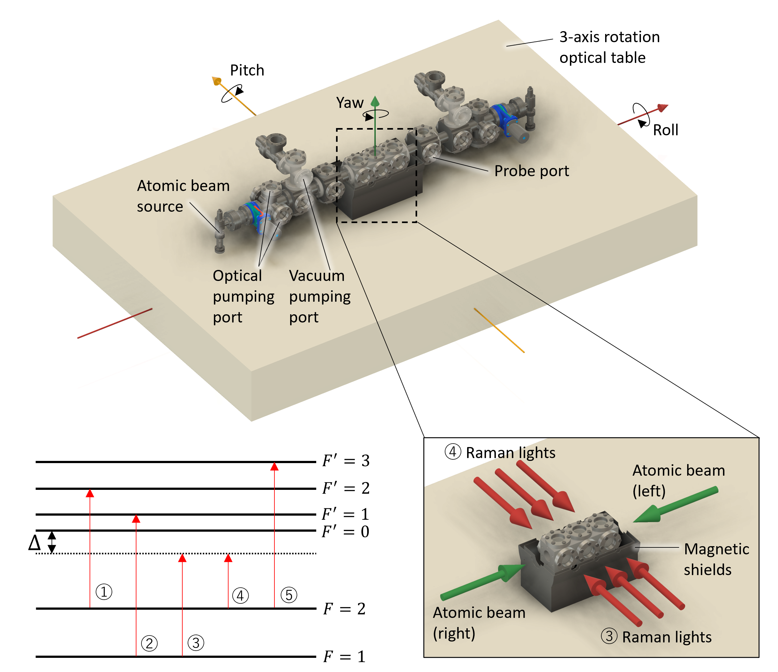
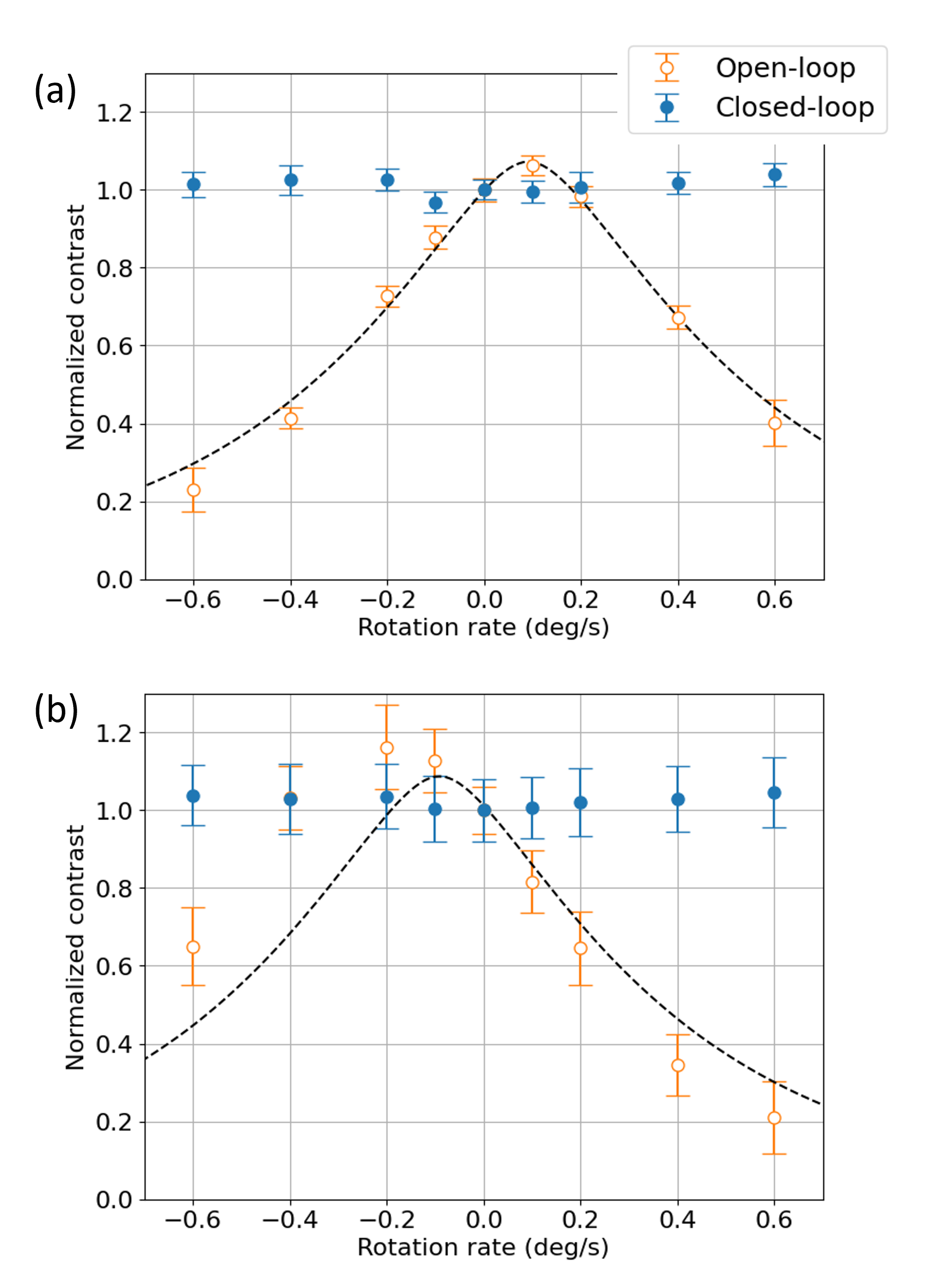
Figure 3 shows the rotation rate dependence of the contrast of interference between right- and left-oriented atomic beams. The value was normalized to the contrast without rotation of the optical table. The contrast decay dependence on the rotation rate with the open-loop measurement was in good agreement with the theoretical prediction from calculated by Eq. (2). In the calculation, actual experimental conditions were used: the mean velocity of the atoms at escaping from the tube was , and the arm length was . The shifts in the peak positions in the theoretical curve for the open-loop measurement were due to the phase shift caused by the detuning of the second Raman light for lock-in detection, as described by the third term in Eqs. (4a) and (4b). The contrast was maximized at the angular velocity, where the actual rotation cancels out the phase shift. The slight deviation in the measured peak position from the theoretical curve in the interferometer with the left-oriented beam is attributed to the imperfect alignment of the relative angles of the Raman beams against the atomic beam. For closed-loop dispersion compensation, two-photon detunings for the first and third Raman lights were adjusted such that the closed-loop condition described in sec. II was achieved. We confirmed that the contrast of the atom interferometers was maintained with the closed-loop method, at a rotation rate of , whereas the contrast deteriorated to 1/5 with the open-loop measurement. We also validated that the contrast did not decay up to a rotation rate of 1, which was limited by the performance of the table.
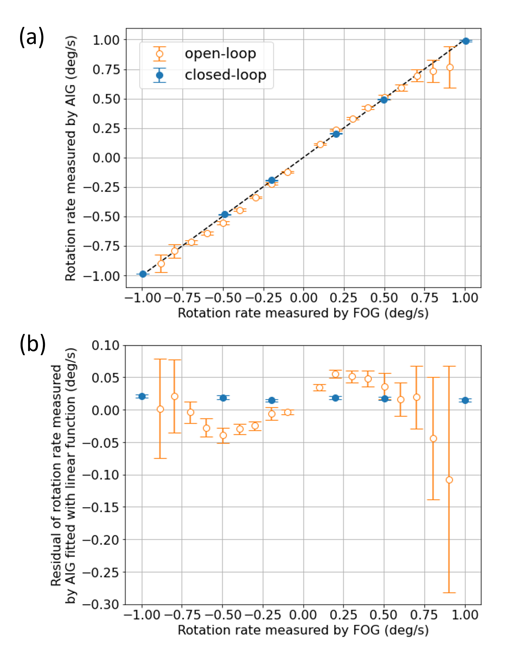
To evaluate the stability of the scale factor, we simultaneously measured the rotation rate of the table using the AIG and commercial FOG (Exail, blueSeis-3A). The scale factor stability of the FOG was below 300 ppm, which had sufficient reliability for validating the concept of our closed-loop technique. Figure 4 (a) shows the rotation rate measured using the AIG with open- and closed-loop measurements as a function of the value evaluated using the FOG. The rotation rate was calculated using Eqs. (6) and (7) for the open- and closed-loop measurements, respectively. Figure 4 (b) shows the residual of the linear fitting of the measured data. The nonlinearity of the scale factor was observed in open-loop measurements. This could be because the higher-order term was neglected in the discussion in the previous sections [43, 31]. With increasing angular velocity, the error bars increased, indicating that interferometer contrast decreased owing to dephasing induced by rotation. In closed-loop measurement, the linearity of the AIG was maintained at a rotation rate of 1∘/s. Because the contrast of the interference did not decrease, the error bar remained small even at a high rotation rate. The slope of the linear fitting of the data acquired using the closed-loop control was 0.9901. The scale factor error is 9,900 ppm, significantly larger than the FOG’s 300 ppm. The cause of this error could be a misadjustment in the Raman light separation or another systematic error source, which will be addressed in Section IV.
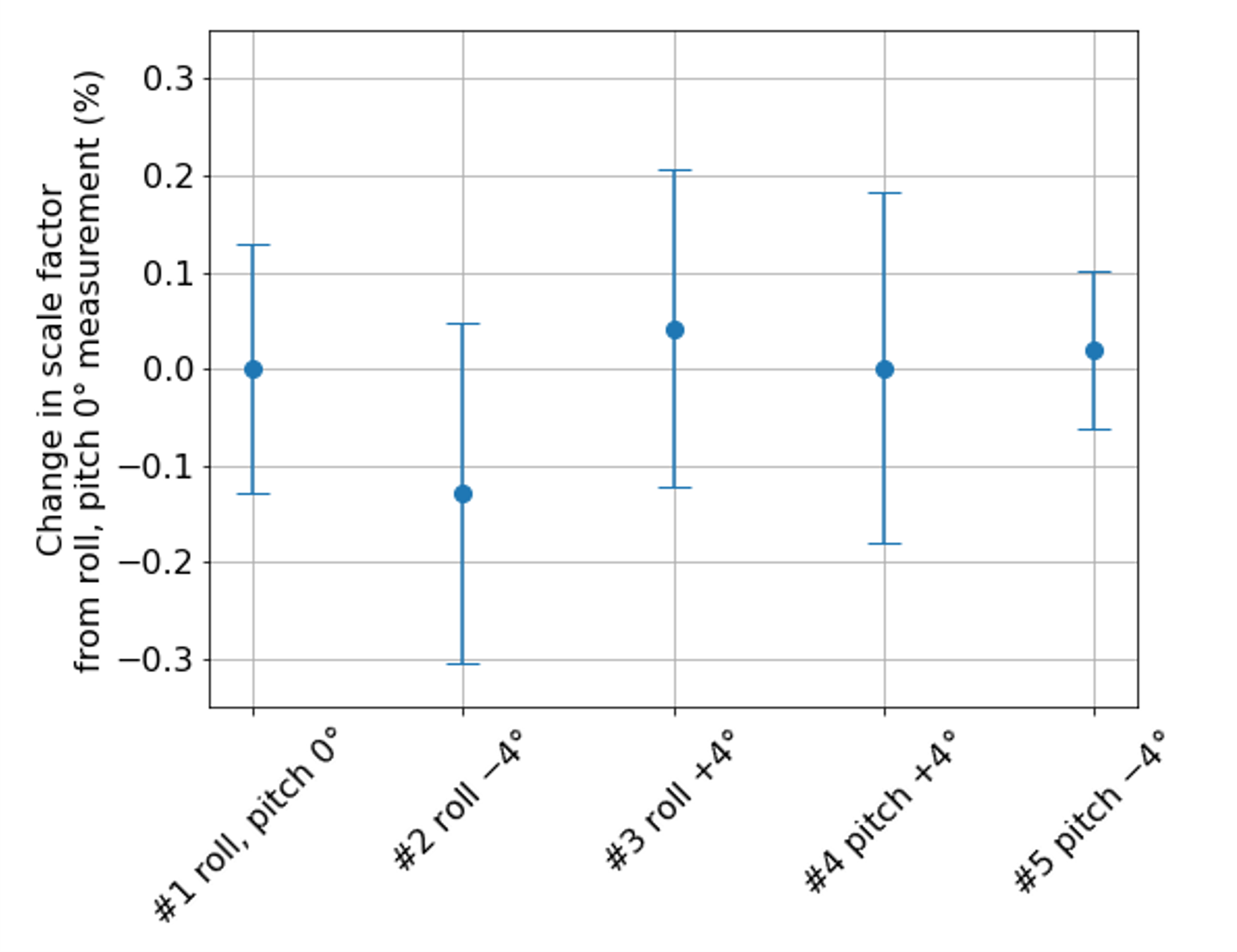
The acceleration provides the same amount of phase offset to the interferometers with counterpropagating atomic beams. Therefore, the measurement of the rotation rate is unaffected by the acceleration of the system in closed-loop measurements, where the phase difference between the two interferometers is assumed to be zero. We confirmed this feature by evaluating the rotation rate of the system while applying constant acceleration using a projective component of Earth’s gravity in the closed-loop measurement, as shown in Fig. 5. In the first measurement, the rotation table was leveled horizontally. For the second and third measurements, acceleration was applied to the axis to which the interferometer was sensitive. When the optical table was tilted by 4∘ along this axis, it resulted in an acceleration of 0.68 . Consequently, a phase offset of 28.4∘ was observed for both interferometers. Even if the phases of individual interferometers change owing to acceleration, the difference between them is not affected, allowing for accurate rotation rate measurements. In the fourth and fifth measurements, the interferometer was not sensitive to acceleration, whereas the velocity of the atom was affected, causing an error in the scale factor in the open-loop measurement. For the closed-loop measurement, because the scale factor did not include the velocity of the atoms, the measured values were unaffected by the acceleration given the current measurement sensitivity. In the next section, we discuss the effect of the velocity difference between the atomic beams.
IV Discussion
In principle, our closed-loop method can be applied to a spatial-domain atom interferometer with any velocity distribution of the atomic beam, including thermal and cold atomic beam sources [6, 44, 45, 46]. This is particularly beneficial for an interferometer with thermal atomic beams that cannot be laser-cooled efficiently because of their broad velocity distribution and short interaction time stemming from their high longitudinal velocity. With our method, the effect of the velocity distribution of the atoms used in interferometry will only appear as a reduction of contrast owing to deviations from the – and –pulse conditions of Raman lights.
Here, we discuss the conditions simplified in Section II to describe the concept of the phase-dispersion compensation using the closed-loop technique. The distance between the last Raman light and the detection region, , may vary for each atomic beam. By substituting in Eq. (4a) and (4b) with and , Eq. (5) is modified as follows:
| (8) |
Assuming that the detuning of the first and third Raman light is , the angular velocity can be deduced as:
| (9) |
in the closed-loop measurements. In this study, the output phase of the interferometer is swept with a finite , resulting in sinusoidal oscillation in the fluorescence signal for lock-in phase detection. Although this condition introduces an error in the measurement, it can be compensated with a single initial calibration if is a fixed frequency, because is constant in measurements. Furthermore, in closed-loop measurements, we can achieve the condition by adjusting the position of the probe light such that the measured angular velocities are not affected by , which vary under a constant known angular velocity, because Eq. (9) is independent to if .
The discussion in Section II also assumes that the absolute values of the velocities of the right- and left-oriented atomic beams are equal. In this case, the effect of acceleration on the rotation rate measurement can be ignored, because the term originating from the acceleration disappears when the phase difference of the atomic interferometer is considered with the right- and left-oriented atomic beams. Let us consider the case in which there is a velocity difference between counterpropagating atomic beams. If the velocity of the atoms is expressed as using the positive constant , the phase difference between interferometers can be written as
| (10) |
with . When and is satisfied, the angular velocity is obtained independently of with by finding the for which the phase difference to be zero. Similar results are obtained when the atomic beams have equal velocities.
When and have finite values, the estimated value of will depend on the difference in the velocities of the atomic beams. To estimate the effects of different atomic beam velocities quantitatively, it is essential to consider the velocity distribution of the atomic beams. This is because if a pair of atoms with the same velocity is present in the velocity distribution of the counterpropagating atomic beams, the phase shift due to acceleration is canceled out for that pair of atoms. Only the atoms at either end of the velocity distribution that do not have a velocity counterpart are expected to contribute to the velocity-dependent systematic errors. These atoms are expected to account for a relatively small proportion of the total number of atoms. We performed numerical calculations to estimate the amount of error that can be introduced into the rotation rate measurements in practical situations. We employed an AIG using atomic beams with an arm length of 70 mm. and were set to the same length because these values could be precisely adjusted using the method stated previously. The temperatures of the atomic sources were set at and , assuming an upper limit for the temperature difference that would be achievable with a commercial temperature controller. The velocity distributions of the atoms were obtained using the Boltzmann distribution of the free molecular flow escaping from the tube channel [47]. Under the condition of Hz adopted in the current experiment, a phase shift corresponding to ∘/s ( rad/s) was induced in , which was much smaller than the current measurement sensitivity. This systematic error can be eliminated through combinations with other techniques, such as the “area reversal” technique using the sign dependency of the phase outputs of the interferometers on [6, 48]. Furthermore, using the recently proposed method of signal acquisition through phase modulation without frequency sweeping of the Raman light [49], the systematic error due to finite will nullify because can be set to zero. With a finite acceleration of , which was applied in this experiment, a phase shift corresponding to ∘/s ( rad/s) appears in . This systematic error can be eliminated through a real-time correction using Kalman filtering with acceleration of the system and temperature of sources measured by other sensors.
As we have considered in this paper, as long as the Sagnac phase only depends on , our closed-loop technique can be applied to any atomic beam with any distribution, and can prevent a decrease in interferometer contrast. Deviations from the current discussion will be observed in the region of large angular velocities where higher-order terms such as become significant. In addition, cross-coupling due to three-dimensional motion will limit the dynamic range of measurement [33]. A more detailed evaluation of these effects will be presented in a forthcoming paper.
V Summary
The Sagnac phase, which reflects the rotation in atom interferometry, depends on the velocity of the atoms. Owing to a velocity distribution of the atoms, individual atoms within the interferometer produce varying interference phases, which results in reduced signal amplitude due to phase dispersion. We introduce a method to restore the contrast degradation in the AIG. By setting the frequency detunings to the Raman lights that construct the atom interferometer, we can induce a velocity-dependent phase shift similar to that of the Sagnac effect. This introduces a pseudo-rotation effect that can cancel the rotation of all atoms, even those with a broad velocity distribution. Applying this method to an AIG with counter-propagating atomic beams sharing the same Raman light, we also observed that the rotation rate of the system can be determined independently of the velocity of the atoms from the two-photon detunings at which the phase difference between two interferometers becomes zero. This is achieved by identifying the detunings where the phase difference between the two interferometers reaches zero. We validated our method using an AIG with thermal atomic beams of 87Rb and closed-loop rotation measurements on a three-axis rotation table. The contrast of the interference was maintained even at a rotation rate of 0.6∘/s, which was a significant improvement compared to the 1/5 contrast decrease observed without compensation. The rotation rates measured using the closed-loop AIG were linearly proportional to those measured using the commercial FOG up to a rotation rate of 1.0∘/s. We also demonstrated the robustness of our closed-loop rotation rate measurements against acceleration, utilizing the projective component of gravity within the table roll and pitch-tilting in the range of 4∘. We performed numerical calculations and found that the possible systematic errors can be eliminated by combination with other techniques and measurements. Moreover, we also found that higher performance can be achieved in combination with other proposed techniques. With its simple and robust closed-loop mechanism using Raman light detuning, our method holds promise for high-dynamic-range applications such as the inertial navigation of vehicles.
Acknowledgements.
We thank Ryotaro Inoue and Yuichiro Kamino for the helpful discussions. This work was supported by the Japan Science and Technology Agency (JST), Grant Numbers JPMJMI17A3 and JPMJPF2015.References
- Kasevich and Chu [1991] M. Kasevich and S. Chu, Atomic interferometry using stimulated Raman transitions, Physical Review Letters 67, 181 (1991), publisher: American Physical Society.
- Kasevich and Chu [1992] M. Kasevich and S. Chu, Measurement of the gravitational acceleration of an atom with a light-pulse atom interferometer, Applied Physics B 54, 321 (1992).
- Lautier et al. [2014] J. Lautier, L. Volodimer, T. Hardin, S. Merlet, M. Lours, F. Pereira Dos Santos, and A. Landragin, Hybridizing matter-wave and classical accelerometers, Applied Physics Letters 105, 144102 (2014).
- Cheiney et al. [2018] P. Cheiney, L. Fouché, S. Templier, F. Napolitano, B. Battelier, P. Bouyer, and B. Barrett, Navigation-Compatible Hybrid Quantum Accelerometer Using a Kalman Filter, Physical Review Applied 10, 034030 (2018), publisher: American Physical Society.
- Gustavson et al. [2000] T. L. Gustavson, A. Landragin, and M. A. Kasevich, Rotation sensing with a dual atom-interferometer Sagnac gyroscope, Classical and Quantum Gravity 17, 2385 (2000).
- Durfee et al. [2006] D. S. Durfee, Y. K. Shaham, and M. A. Kasevich, Long-Term Stability of an Area-Reversible Atom-Interferometer Sagnac Gyroscope, Physical Review Letters 97, 240801 (2006).
- Savoie et al. [2018] D. Savoie, M. Altorio, B. Fang, L. A. Sidorenkov, R. Geiger, and A. Landragin, Interleaved atom interferometry for high-sensitivity inertial measurements, Science Advances 4, eaau7948 (2018), publisher: American Association for the Advancement of Science.
- Avinadav et al. [2020] C. Avinadav, D. Yankelev, M. Shuker, O. Firstenberg, and N. Davidson, Rotation sensing with improved stability using point-source atom interferometry, Physical Review A 102, 013326 (2020), publisher: American Physical Society.
- Gebbe et al. [2021] M. Gebbe, J.-N. Siemß, M. Gersemann, H. Müntinga, S. Herrmann, C. Lämmerzahl, H. Ahlers, N. Gaaloul, C. Schubert, K. Hammerer, S. Abend, and E. M. Rasel, Twin-lattice atom interferometry, Nature Communications 12, 2544 (2021), publisher: Nature Publishing Group.
- Peters et al. [2001] A. Peters, K. Y. Chung, and S. Chu, High-precision gravity measurements using atom interferometry, Metrologia 38, 25 (2001).
- Hu et al. [2013] Z.-K. Hu, B.-L. Sun, X.-C. Duan, M.-K. Zhou, L.-L. Chen, S. Zhan, Q.-Z. Zhang, and J. Luo, Demonstration of an ultrahigh-sensitivity atom-interferometry absolute gravimeter, Physical Review A 88, 043610 (2013), publisher: American Physical Society.
- Li et al. [2023] C.-Y. Li, J.-B. Long, M.-Q. Huang, B. Chen, Y.-M. Yang, X. Jiang, C.-F. Xiang, Z.-L. Ma, D.-Q. He, L.-K. Chen, and S. Chen, Continuous gravity measurement with a portable atom gravimeter, Physical Review A 108, 032811 (2023), publisher: American Physical Society.
- Snadden et al. [1998] M. J. Snadden, J. M. McGuirk, P. Bouyer, K. G. Haritos, and M. A. Kasevich, Measurement of the Earth’s Gravity Gradient with an Atom Interferometer-Based Gravity Gradiometer, Physical Review Letters 81, 971 (1998), publisher: American Physical Society.
- McGuirk et al. [2002] J. M. McGuirk, G. T. Foster, J. B. Fixler, M. J. Snadden, and M. A. Kasevich, Sensitive absolute-gravity gradiometry using atom interferometry, Physical Review A 65, 033608 (2002), publisher: American Physical Society.
- Rosi et al. [2014] G. Rosi, F. Sorrentino, L. Cacciapuoti, M. Prevedelli, and G. M. Tino, Precision measurement of the Newtonian gravitational constant using cold atoms, Nature 510, 518 (2014), publisher: Nature Publishing Group.
- Parker et al. [2018] R. H. Parker, C. Yu, W. Zhong, B. Estey, and H. Müller, Measurement of the fine-structure constant as a test of the Standard Model, Science 360, 191 (2018), publisher: American Association for the Advancement of Science.
- Dimopoulos et al. [2008] S. Dimopoulos, P. W. Graham, J. M. Hogan, M. A. Kasevich, and S. Rajendran, Atomic gravitational wave interferometric sensor, Physical Review D 78, 122002 (2008), publisher: American Physical Society.
- Canuel et al. [2018] B. Canuel, A. Bertoldi, L. Amand, E. Pozzo di Borgo, T. Chantrait, C. Danquigny, M. Dovale Álvarez, B. Fang, A. Freise, R. Geiger, J. Gillot, S. Henry, J. Hinderer, D. Holleville, J. Junca, G. Lefèvre, M. Merzougui, N. Mielec, T. Monfret, S. Pelisson, M. Prevedelli, S. Reynaud, I. Riou, Y. Rogister, S. Rosat, E. Cormier, A. Landragin, W. Chaibi, S. Gaffet, and P. Bouyer, Exploring gravity with the MIGA large scale atom interferometer, Scientific Reports 8, 14064 (2018), publisher: Nature Publishing Group.
- Zhan et al. [2020] M.-S. Zhan, J. Wang, W.-T. Ni, D.-F. Gao, G. Wang, L.-X. He, R.-B. Li, L. Zhou, X. Chen, J.-Q. Zhong, B. Tang, Z.-W. Yao, L. Zhu, Z.-Y. Xiong, S.-B. Lu, G.-H. Yu, Q.-F. Cheng, M. Liu, Y.-R. Liang, P. Xu, X.-D. He, M. Ke, Z. Tan, and J. Luo, ZAIGA: Zhaoshan long-baseline atom interferometer gravitation antenna, International Journal of Modern Physics D 29, 1940005 (2020), publisher: World Scientific Publishing Co.
- Abe et al. [2021] M. Abe, P. Adamson, M. Borcean, D. Bortoletto, K. Bridges, S. P. Carman, S. Chattopadhyay, J. Coleman, N. M. Curfman, K. DeRose, T. Deshpande, S. Dimopoulos, C. J. Foot, J. C. Frisch, B. E. Garber, S. Geer, V. Gibson, J. Glick, P. W. Graham, S. R. Hahn, R. Harnik, L. Hawkins, S. Hindley, J. M. Hogan, Y. Jiang, M. A. Kasevich, R. J. Kellett, M. Kiburg, T. Kovachy, J. D. Lykken, J. March-Russell, J. Mitchell, M. Murphy, M. Nantel, L. E. Nobrega, R. K. Plunkett, S. Rajendran, J. Rudolph, N. Sachdeva, M. Safdari, J. K. Santucci, A. G. Schwartzman, I. Shipsey, H. Swan, L. R. Valerio, A. Vasonis, Y. Wang, and T. Wilkason, Matter-wave Atomic Gradiometer Interferometric Sensor (MAGIS-100), Quantum Science and Technology 6, 044003 (2021), publisher: IOP Publishing.
- Panda et al. [2024] C. D. Panda, M. J. Tao, M. Ceja, J. Khoury, G. M. Tino, and H. Müller, Measuring gravitational attraction with a lattice atom interferometer, Nature , 1 (2024), publisher: Nature Publishing Group.
- Geiger et al. [2011] R. Geiger, V. Ménoret, G. Stern, N. Zahzam, P. Cheinet, B. Battelier, A. Villing, F. Moron, M. Lours, Y. Bidel, A. Bresson, A. Landragin, and P. Bouyer, Detecting inertial effects with airborne matter-wave interferometry, Nature Communications 2, 474 (2011), publisher: Nature Publishing Group.
- Barrett et al. [2016] B. Barrett, L. Antoni-Micollier, L. Chichet, B. Battelier, T. Lévèque, A. Landragin, and P. Bouyer, Dual matter-wave inertial sensors in weightlessness, Nature Communications 7, 13786 (2016), publisher: Nature Publishing Group.
- Bidel et al. [2018] Y. Bidel, N. Zahzam, C. Blanchard, A. Bonnin, M. Cadoret, A. Bresson, D. Rouxel, and M. F. Lequentrec-Lalancette, Absolute marine gravimetry with matter-wave interferometry, Nature Communications 9, 627 (2018), publisher: Nature Publishing Group.
- Bidel et al. [2020] Y. Bidel, N. Zahzam, A. Bresson, C. Blanchard, M. Cadoret, A. V. Olesen, and R. Forsberg, Absolute airborne gravimetry with a cold atom sensor, Journal of Geodesy 94, 20 (2020).
- Antoni-Micollier et al. [2024] L. Antoni-Micollier, M. Arnal, R. Gautier, C. Janvier, V. Ménoret, J. Richard, P. Vermeulen, P. Rosenbusch, C. Majek, and B. Desruelle, Absolute quantum gravimeters and gradiometers for field measurements (2024), arXiv:2405.10844 [physics], arXiv:2405.10844 .
- Titterton and Weston [2004] D. Titterton and J. L. Weston, Strapdown Inertial Navigation Technology, 2nd ed. (Institution of Engineering and Technology, London, 2004) google-Books-ID: WwrCrn54n5cC.
- Lèfevre et al. [2020] H. C. Lèfevre, A. Steib, A. Claire, A. Sekeriyan, A. Couderette, A.-L. Pointel, A. Viltard, A. Bonnet, A. Frénois, A. Gandoin, A. Laurent, A. Luton, A. Galbès, A. Ecarnot, B. Cadier, B. Kerouanton, B. Lhermitte, B. Bonnafé, C. Stuber, C. Ortiz, C. Moluçon, C. Allano, C. Dunette, C. Ollivier, C. Guyot, C. Vercambre, D. Ponceau, D. Ramecourt, E. d. Toldi, E. Peter, E. Ducloux, E. Vassilakis, F. Colliou, F. Napolitano, F. Lauvinerie, F. Guattari, G. Fauquert, G. Mélin, G. Hardy, G. Lecamp, H. Porte, H. Jaheny, H. Boiron, J.-J. Bonnefois, J.-P. Michel, J.-P. Périot, J. Pillon, J. Hauden, J. Honthaas, K. Aubry, K. Gauthier, L. Lablonde, L. Ly, L. Lhomme, L. Poulain, M. Girault, M. Mancini, M. Goudron, M.-L. Duplaquet, M. Bernasconi, M. Collignon, M. Dacheux, M. Rattier, M. Marta, N. Faussot, N. Grossard, N. Pirrone, O. Jolly, O. Rabine, P. Guitton, P. Mollier, P. Simonpiétri, P. Buisson, P. Cheiney, P. Chakma, R. Taibi, R. Blondeau, S. Shariati, S. Boisgontier, S. Ferrand, S. Keller, S. Huet, S. Chouvin, S. Meyer, S. Puille, S. Ustaze, S. Bénard, S. Clémenceau, T. Laudat, T. Guettler-Sergeant, T. D. Santos, T. Peou-Sanson, T. Robin, T. Buret, T. Loret, T. Villedieu, V. Ferreira, V. D. Pham, V. Rumoroso, Y. Paturel, and H. J. Arditty, The fiber optic gyro ’adventure’ at Photonetics, iXsea and now iXblue, Proceedings of SPIE, Optical Waveguide and Laser Sensors 11405, 114050 (2020).
- Lèfevre [2022] H. C. Lèfevre, The Fiber-Optic Gyroscope, 3rd ed. (Artech House, Boston, 2022).
- Song et al. [2023] N. Song, X. Xu, Z. Zhang, F. Gao, and X. Wang, Advanced Interferometric Fiber Optic Gyroscope for Inertial Sensing: A Review, Journal of Lightwave Technology 41, 4023 (2023), conference Name: Journal of Lightwave Technology.
- Hogan et al. [2009] J. M. Hogan, D. M. S. Johnson, and M. A. Kasevich, Light-pulse atom interferometry, in Atom Optics and Space Physics (IOS Press, Amsterdam, 2009) pp. 411–447.
- Fang and Qin [2012] J. Fang and J. Qin, Advances in Atomic Gyroscopes: A View from Inertial Navigation Applications, Sensors 12, 6331 (2012), number: 5 Publisher: Molecular Diversity Preservation International.
- Narducci et al. [2022] F. A. Narducci, A. T. Black, and J. H. Burke, Advances toward fieldable atom interferometers, Advances in Physics: X 7, 1946426 (2022), publisher: Taylor & Francis _eprint: https://doi.org/10.1080/23746149.2021.1946426.
- Sagnac [1913a] G. Sagnac, L’ether lumineux demontre par l’effet du vent relatif d’ether dans un interferometre en rotation uniforme, Comptes Rendus de l’Académie des Sciences Paris 157, 708 (1913a).
- Sagnac [1913b] G. Sagnac, La preuve de la réalité de l’éther lumineux par l’expérience de l’interférographe tournant, Comptes Rendus de l’Académie des Sciences Paris 157, 1410 (1913b).
- Storey and Cohen-Tannoudji [1994] P. Storey and C. Cohen-Tannoudji, The Feynman path integral approach to atomic interferometry. A tutorial, Journal de Physique II 4, 1999 (1994), publisher: EDP Sciences.
- Kwolek et al. [2020] J. Kwolek, C. Fancher, M. Bashkansky, and A. Black, Three-Dimensional Cooling of an Atom-Beam Source for High-Contrast Atom Interferometry, Physical Review Applied 13, 044057 (2020), publisher: American Physical Society.
- d’Armagnac de Castanet et al. [2024] Q. d’Armagnac de Castanet, C. D. Cognets, R. Arguel, S. Templier, V. Jarlaud, V. Ménoret, B. Desruelle, P. Bouyer, and B. Battelier, Atom interferometry at arbitrary orientations and rotation rates (2024), arXiv:2402.18988 [physics, physics:quant-ph], arXiv:2402.18988 .
- Ekstrom et al. [1995] C. R. Ekstrom, J. Schmiedmayer, M. S. Chapman, T. D. Hammond, and D. E. Pritchard, Measurement of the electric polarizability of sodium with an atom interferometer, Physical Review A 51, 3883 (1995), publisher: American Physical Society.
- Jacquey et al. [2008] M. Jacquey, A. Miffre, G. Trénec, M. Büchner, J. Vigué, and A. Cronin, Dispersion compensation in atom interferometry by a Sagnac phase, Physical Review A 78, 013638 (2008), publisher: American Physical Society.
- Berman [1997] P. R. Berman, ed., Atom Interferometry, 1st ed. (Academic Press, San Diego, 1997).
- Luo et al. [2021] Y. Luo, J. You, Q. Hu, Y. Li, M. Ma, J. Wang, and F. Xu, Reanalyzing Atomic Beam Interferometric Gyroscopes: Dependence of Sensitivity on Experimental Parameters, IEEE Sensors Journal 21, 1433 (2021), conference Name: IEEE Sensors Journal.
- Bongs et al. [2006] K. Bongs, R. Launay, and M. Kasevich, High-order inertial phase shifts for time-domain atom interferometers, Applied Physics B 84, 599 (2006).
- Kwolek and Black [2022] J. M. Kwolek and A. T. Black, Continuous Sub-Doppler-Cooled Atomic Beam Interferometer for Inertial Sensing, Physical Review Applied 17, 024061 (2022), publisher: American Physical Society.
- Hosoya et al. [2023] T. Hosoya, R. Inoue, T. Sato, and M. Kozuma, High-flux cold ytterbium atomic beam source using two-dimensional laser cooling with intercombination transition, Optics Communications 528, 129048 (2023).
- Meng et al. [2024] Z.-X. Meng, P.-Q. Yan, S.-Z. Wang, X.-J. Li, H.-B. Xue, and Y.-Y. Feng, Closed-loop dual-atom-interferometer inertial sensor with continuous cold atomic beams, Physical Review Applied 21, 034050 (2024), publisher: American Physical Society.
- Ramsey [1986] N. Ramsey, Molecular Beams (Oxford University Press, Oxford, 1986).
- Black et al. [2024] A. T. Black, H. J. Haucke, S. Upadhyay, R. K. O’Donnell, and J. M. Kwolek, Time-domain control of a spatial-domain atomic beam interferometer, Proceedings of SPIE, Quantum Sensing, Imaging, and Precision Metrology II 12912, 129120K (2024).
- Kawasaki et al. [2024] T. Kawasaki, S. Otabe, T. Sato, M. Miranda, N. Takei, and M. Kozuma, Analyzing the sensitivity of an atom interferometer with a phase modulation readout scheme (2024), arXiv:2406.03911 [physics, physics:quant-ph], arXiv:2406.03911 .