Current-induced motion of nanoscale magnetic torons
over the wide range of the Hall angle
Abstract
Current-driven dynamics of spin textures plays a pivotal role in potential applications for electronic devices. While two-dimensional magnetic skyrmions with topologically nontrivial spin textures have garnered significant interest, their practical use is hindered by the skyrmion Hall effect — a transverse motion to the current direction that occurs as a counteraction to the topological Hall effect of electrons by an emergent magnetic field arising from the Berry phase effect. Here, we explore current-driven dynamics of three-dimensional topological spin textures known as magnetic torons, composed of layered skyrmions with two singularities called Bloch points at their ends. Through extensive numerical simulations, we show that the torons also exhibit a Hall motion, but surprisingly over a wide range spanning from the zero Hall effect, a purely longitudinal motion, to the perfect Hall effect, a purely transverse motion accompanied by no longitudinal motion. Such flexible and controllable behaviors stem from anisotropic potential barriers on the discrete lattice, which can be particularly relevant for nanoscale torons recently discovered. Our results not only provide an experimental method to probe topology of three-dimensional magnetic textures but also pave the way for future developments in topological spintronics beyond the realm of skyrmions.
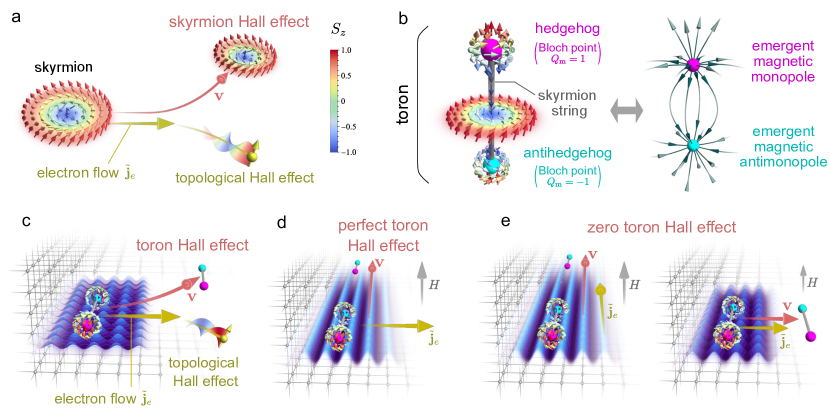
Research in the field of topological spin textures has opened a new era for electronics and spintronics by leveraging the synergy between electronic and magnetic properties through topology. Of particular interest are two-dimensional magnetic skyrmions with swirling spin textures characterized by a topological invariant called the skyrmion number (Fig. 1a). The skyrmion was originally hypothesized in the field of particle physics [1, 2], and later theoretically predicted to be realized in chiral magnets [3, 4, 5, 6] and actually observed in experiments in a form of a triangular array [7, 8]. Owing to their inherent topological stability, skyrmions have drawn attention as entirely new information carriers in next-generation spintronic devices. They also offer a significant advantage in terms of energy consumption, as they can be driven at much lower electric current densities [9]. However, the current-driven skyrmions exhibit a transverse motion relative to the current direction, known as the skyrmion Hall effect [9, 10, 11, 12]. This is caused by the Magnus force as a counteraction to the topological Hall effect of electrons, as schematically shown in Fig. 1a, arising from the emergent magnetic field (EMF) by the Berry phase effect, , given by , where is the Levi-Civita symbol and represents the spin at spatial position [13, 14]. This lateral motion presents challenges in device applications of magnetic skyrmions, although various strategies have been proposed, such as utilizing antiferromagnetic skyrmions that do not exhibit the skyrmion Hall effect [15, 16].
In three-dimensional space, skyrmions manifest as string-like structures, stacked in the out-of-plane direction. This skyrmion string may terminate in some cases, and at these endpoints, unique three-dimensional topological spin textures emerge. They are known as the Bloch points and were observed by using 3D tomographic imaging techniques [17, 18, 19, 20]. These Bloch points are also characterized by a topological invariant called the monopole charge, which is defined by a surface integral of the EMF on a sphere surrounding the Bloch point, and classified into two types depending on the sign of the monopole charge: magnetic hedgehogs and antihedgehogs with positive and negative monopole charges, respectively [14, 21]. They typically appear in pairs at both ends of a skyrmion string and such a pair is called the magnetic toron (Fig. 1b) [22]. Unlike skyrmions, the hedgehogs and antihedgehogs have singularities with vanishing spin length at their cores, which can be regarded as sources and sinks in terms of the EMF, thus acting as emergent magnetic monopoles and antimonopoles, respectively.
Recent experiments have demonstrated that such magnetic torons are stabilized by forming periodic arrangements called the hedgehog lattices (HLs) in chiral magnets MnSi1-xGex [23, 24, 25, 26] and a nonchiral magnet SrFeO3 [27]. Notably, these HLs have remarkably short magnetic pitches, with hedgehogs and antihedgehogs spanning only a few nanometers in size, suggesting a giant EMF around them caused by a strong twist of the spin textures. Due to the EMF as well as the topological robustness, Bloch points are expected to exhibit peculiar electromagnetic responses like skyrmions, but their current-driven dynamics remains largely unexplored, except for an isolated Bloch point or toron in the long-wavelength limit [28, 29]. Given that smaller texture sizes are preferable for EMF-based devices, it is imperative to investigate the current-driven dynamics of these short-pitch HLs to advance future spintronic devices beyond the capabilities of skyrmions.
Here, we examine the responses of nanoscale magnetic torons to an applied electric current by extensive numerical simulations. We show that, similar to skyrmions, the torons exhibit a Hall motion, which we call the toron Hall effect (Fig. 1c). Strikingly, we discover that the toron Hall effect can be controlled by the electric current and the magnetic field in a wide range including two extremes: a purely transverse motion without any longitudinal one (perfect toron Hall effect; Fig. 1d) and an exclusively longitudinal motion with no transverse one (zero toron Hall effect; Fig. 1e). These unique behaviors stem from the modulation of potential barriers on the discrete lattice, which is particularly relevant for the nanoscale torons realized in experiments. Furthermore, we reveal that the responses to the current act as efficient electrical probes for topological characteristics hidden behind the spin textures that are challenging to observe experimentally.
Toron Hall effect
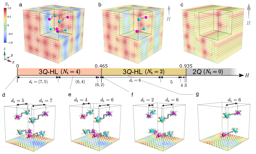
To elucidate the current-induced dynamics of magnetic torons, we consider a spin model for a metallic chiral magnet on a simple cubic lattice, and perform a real-time simulation in an electric current based on the Landau-Lifshitz-Gilbert equation. The model includes effective interactions of Ruderman-Kittel-Kasuya-Yosida and Dzyaloshinskii-Moriya (DM) types, which has been shown to approximately reproduce the HLs discovered in MnSi1-xGex [30, 31, 32] (see Methods). In the absence of the electric current, the model stabilizes a HL represented by the superposition of three spin density waves, called the -HL, at zero magnetic field (Fig. 2a) (see Supplementary Note 1). The magnetic unit cell (MUC) contains eight Bloch points (hedgehogs and antihedgehogs), which are connected in four pairs by the skyrmion strings (Fig. 2d); namely, there are four torons denoted as . In the magnetic field applied in the direction, , the hedgehogs and antihedgehogs move toward each other along the skyrmion strings (Figs. 2e,f), and the half of them disappear with pair annihilation at , leading to the topological transition to the -HL with (Figs. 2b,g). By further increasing , the system turns into a state at , which is topologically trivial with no Bloch points ( (Fig. 2c).
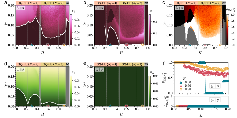
Let us first discuss drift motions caused by an electron flow in the direction perpendicular to the skyrmion strings (see Methods). We find that the magnetic torons exhibit a transverse motion to the electron flow due to the Magnus force as well as a longitudinal one over the wide range of the HL phases under the magnetic field. We call this the toron Hall effect. Remarkably, however, the velocities of the longitudinal and transverse motions, and , respectively, show largely different and complicated dependences on and . Figures 3a and 3b summarize and , respectively, on the - plane. The longitudinal motion occurs above a certain threshold current density represented by the white curve; overall increases with , except significant reduction near the topological transition at . Above , monotonically increases with . Meanwhile, the transverse motion also occurs above a threshold , but it shows a sharp dip at and becomes vanishingly small for . The dip corresponds to a shortening of the skyrmion strings (Fig. 2); we will discuss this later. In addition, exhibits nonmonotonic behavior while increasing across ; most significantly, around , it becomes nonzero above , but vanishes for . We also note that vanishes in the weak field region where in this range of due to the weak Magnus force stemming from small EMF (see Supplementary Note 1).
These distinct behaviors of and indicate that the system exhibits the toron Hall effect in a wide range including two extreme limits. One is a purely transverse motion without any longitudinal one ( and ), appearing in the region where . We call this the perfect toron Hall effect. The other is opposite: a purely longitudinal motion accompanied with no transverse one ( and ), occurring in the region where vanishes despite . We call this the zero toron Hall effect. These two extreme behaviors can be explicitly visualized by plotting the Hall angle defined by
| (1) |
which represents the net direction of the drift motion with respect to the electron flow (Fig. 3c). The perfect and zero toron Hall effects correspond to and , respectively, shown by the white and black regions. The former occurs in the wide range of , especially for small in the -HL with after the topological transition, while the latter appears in the -HL with for .
Notably, one can achieve the zero toron Hall effect over a wider range of and simply by changing the current direction. We demonstrate this by taking the electron flow in the direction along the skyrmion strings (). In this case also, the longitudinal motion occurs above nonzero threshold (Fig. 3d); shows a different dependence from the case with characteristic dip structures, which will be discussed later. We note that cannot be defined in the phase since the spin modulation in the direction is absent (see Supplementary Note 1). In stark contrast, the transverse motion is not observed at all in this parameter region (Fig. 3e). Thus, with this current setting, the zero toron Hall effect appears in the entire region for .
Our results show that the toron Hall effect is much more flexible than the skyrmion Hall effect. It can be controlled by the amplitudes and directions of the magnetic field and the electric current. Most strikingly, it includes two extremes, the zero and perfect toron Hall effects, which have never been reported in the skyrmion Hall effect. By choosing appropriate parameters, one can even achieve switching between the two extremes, as demonstrated in Fig. 3f: By increasing for at , the perfect toron Hall effect is observed for (Supplementary Video 1), followed by the zero toron Hall effect for (Supplementary Video 2), and finally, the toron Hall effect with appears for (Supplementary Video 3).
We note that the toron Hall effect vanishes when we turn off the DM-type interaction in our model for the -HL (see Supplementary Note 5). Nonetheless, this does not mean that the toron Hall effect never occur in nonchiral magnets. In general, the net EMF can be nonzero even in nonchiral cases in the presence of spin-orbit coupling, leading to the topological Hall effect as observed in SrFeO3 [33], allowing the toron Hall effect as its counteraction.
Anisotropic potential barrier
The peculiar toron Hall effect originates from the energy potential for torons on the discrete lattice. Drift motions of nanoscale torons are strongly affected by the lattice discretization due to their short magnetic pitch and singular structures of constituting Bloch points. The magnetic field influences the spin textures, resulting in energy potential modulation in an anisotropic manner. This causes the different and complicated dependences of and , as demonstrated below.
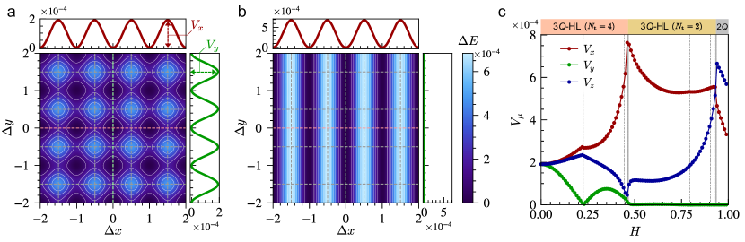
When , the energy potential for torons on the plane is fourfold rotational symmetric reflecting the lattice symmetry (Fig. 4a). Here, we plot the energy increase per site by shifting the spin texture with from the ground state. The potential oscillates with the lattice period, and the heights of the potential barrier in the and directions are equivalent, . In this case, an electric current required for torons to overcome the potential barrier is equal for and , resulting in in both cases (Figs. 3a,d). By introducing , increases but decreases; namely, the potential develops a one-dimensional anisotropy through the modulation of the spin texture, giving rise to different threshold current densities for the different current directions. Figure 4b represents an example at , where almost vanishes. Such a highly anisotropic potential causes the unique drift motions including the zero and perfect toron Hall effects found above. On one hand, for , the longitudinal drift motion is hindered by large , while the transverse motion is easily driven with vanishingly small , resulting in . This leads to the perfect toron Hall effect, as illustrated in Fig. 1d. On the other hand, for , the longitudinal drift motion is caused by a small current density, while the transverse motion is largely suppressed, resulting in . This brings about the zero toron Hall effect, as illustrated in the left panel of Fig. 1e. The zero toron Hall effect for in Fig. 3c is also caused by the anisotropic potential, but in more complicated competition between the longitudinal driving force from the electric current and the induced transverse Magnus force (the right panel of Fig. 1e).
Remarkably, the energy potential becomes almost one-dimensional () in the entire -HL phase with after the topological transition (Fig. 4c). The origin of the vanishingly small lies in the suppression of the higher harmonics of the spin structure factor in the direction; the suppression beyond the Nyquist wave number makes the spin texture less susceptible to the lattice discretization (see Supplementary Note 2). It is worth noting that the dependences of the potential barriers qualitatively explain those of the critical current densities: behaves as for (Fig. 3a), and as for (Fig. 3b) and for (Fig. 3d) (for , see Supplementary Note 3). This supports our argument based on the potential barrier on the discrete lattice. We note that does not follow the significant reduction of for near the topological transition in Fig. 3a, but this is accounted for by the Magnus force in the direction longitudinal to the current arising from the transverse drift motion of torons.
Probing hidden topology
Our results indicate that the dependences of the threshold current densities, and , can be a sensitive probe of the topological transition with toron annihilation. This can be complementary to the elastic constant measurements [21]. Furthermore, they are useful for probing more detailed changes in the topological objects, namely the length changes in the skyrmion strings. For instance, for , exhibits a sharp dip at (Fig. 3b), where the lengths of the skyrmion strings change from to in two out of four torons and from to in the rest (Fig. 2). We also observe a small anomaly in (Fig. 3a). A similar sharp dip is also found in for (Fig. 3d), but in this case, a smaller dip is additionally seen at in the -HL with , where the length of the skyrmion string reduces from to in the remaining two torons. These behaviors are understood as follows. The Bloch points locate at the interstitial positions on the lattice so that their cores with vanishing spin length avoid the lattice sites, and hence the energy potential is strongly modulated when the Bloch points traverse between the unit cubes of the lattice with the shortening of the skyrmion strings. Thus, the measurement of the threshold current densities can serve as a probe of not only topological transitions but also detailed changes of topological objects in the lattice spacing scale that are usually hidden in the macroscopic properties [32, 34]. We note that this holds even for nonchiral cases without the DM-type interaction (see Supplementary Note 5).
In experiments, the threshold current densities under the magnetic field can be measured straightforwardly. In the present simulation, corresponds to the electric current density of A/m2, when assuming the energy unit as meV, the lattice constant as nm, and the spin polarization of the current as [11] (see Methods). This is comparable to a typical value required for magnetic domain walls to drive [35]. Thus, the threshold current measurements would provide microscopic information of the topology, complementary to the real-space measurements such as the Lorentz transmission electron microscopy [25] and 3D tomographic imaging techniques [19, 20]. Such measurements for nanoscale HLs discovered in MnSi1-xGex and SrFeO3 are eagerly awaited for the verification of our theoretical prediction.
Concluding remarks
Our comprehensive study of the current-induced dynamics of nanoscale magnetic torons has revealed the extensive controllability of their drift motions spanning from the zero to perfect toron Hall effect. We clarified that such prominent current-induced dynamics arises from the potential barrier on the discrete lattice which can be highly anisotropic through the modulation of the spin textures by the magnetic field. We also found that the field dependence of the threshold current serves as a concise and sensitive probe of the microscopic changes of topological objects.
While the measurement of the threshold currents is experimentally straightforward, their actual values as well as the dependences depend on the crystal structure and its symmetry of the real materials. Our results for the simple cubic lattice need modifications to apply to MnGe with the structure, while they will be rather straightforwardly extended to the cubic perovskite SrFeO3. Nevertheless, we believe that the flexible and controllable toron Hall effect in the wide range of the Hall angle is universally observed for HLs with nanoscale torons because of the short magnetic pitch comparable to the lattice constant and the singularity at the cores of the Bloch points. Extensions of our studies to crystallographic groups other than cubic are intriguing for further explorations. For instance, hexagonal systems may allow zero and perfect toron Hall effects even at zero field because of the symmetry of the energy potential.
Magnetic torons are promising information carriers due to their topological robustness. Our finding of flexible and controllable drift motions will increase their advantage over skyrmions. In the case of skyrmions, it was shown that the current-driven motions are almost free from the lattice discretization, and the Hall motion inevitably occurs, which has hindered the applications of skyrmions to spintronic devices [9, 10, 11]. The extremely high controllability of the toron Hall effect is expected to resolve these issues and lead to future device applications. We note, however, that such a skyrmion motion is partly due to the real-space scale of spin textures much larger than the lattice spacing. Recently, nanoscale skyrmions have been discovered beyond the conventional DM mechanism [36, 37, 38, 39]. Such short-pitch skyrmions would be more susceptible to the lattice discretization compared to conventional long-pitch ones, while they are anticipated to be less sensitive than magnetic torons due to the absence of singularities. Detailed comparisons, including other topological spin textures, will be left to future studies.
Acknowledgements.
The authors thank R. Arita, G.-W. Chern, N. Kanazawa, K. Kobayashi, M. Mochizuki, R. Takagi, and H. Yoshimochi for fruitful discussions. This research was supported by Grant-in-Aid for Scientific Research Grants (Nos. JP19H05822, JP19H05825, JP21J20812, JP22K03509, JP22K13998, and JP23H01119), JST CREST (Nos. JP-MJCR18T2 and JP-MJCR19T3), and the Chirality Research Center in Hiroshima University and JSPS Core-to-Core Program, Advanced Research Networks. K.S. was supported by the Program for Leading Graduate Schools (MERIT-WINGS). Parts of the numerical calculations were performed in the supercomputing systems in ISSP, the University of Tokyo.Methods
Model for metallic chiral magnets
We adopt an effective spin model for metallic chiral magnets with itinerant electrons coupled to localized spins. The electron-spin coupling brings about effective long-range interactions between the localized spins known as the Ruderman-Kittel-Kasuya-Yosida interaction [40, 41, 42]. By extending the argument, the previous studies systematically derived the generalized and multiple-spin interactions in the presence of the spin-orbit coupling, and showed that such extensions stabilize HLs as well as skyrmion lattices with short magnetic pitches [43, 44, 45, 30, 31, 46, 32, 34]. In this study, we consider the symmetry-adapted two-spin interactions for a cubic chiral magnet by following the previous studies [31, 32]. The Hamiltonian reads
| (2) |
where
| (3) |
with
| (7) | |||
| (11) | |||
| (15) | |||
| (16) | |||
| (17) |
Here, denotes the classical spin at the site located at and time (); , , and represent the coefficients for the isotropic exchange, anisotropic exchange, and DM interactions, respectively. The interactions exhibit spatial oscillations arising from the itinerant nature of electrons; we set the wave vectors , , and , which are related with each other by threefold rotational symmetry about the [111] axis. Furthermore, we introduce the spatial decay of the interaction parametrized by as a function of and reduce the numerical cost by limiting the summation in real space for by following the previous studies [31, 47]. The second term in Eq. (2) represents the Zeeman coupling to the magnetic field . We take as the energy unit, set the lattice constant unity, and choose , , , , and . We perform the calculations for the -site system under the periodic boundary condition, which corresponds to the single MUC. We confirm that the results are qualitatively intact for .
Landau-Lifshitz-Gilbert equation
To elucidate the current-induced dynamics of the HL, we study the real-time dynamics of spins by solving the Landau-Lifshitz-Gilbert (LLG) equation given by
| (18) |
where is the Gilbert damping, is the mean magnetic field at time , defined as
| (19) |
Note that the length constraint of is deferred only in the calculation of this derivative. In Eq. (18), is the torque arising from an electric current, which is given by [48, 11]
| (20) |
Here, the effect of the electric current is incorporated as the spin transfer torque; represents the normalized velocity of conduction electrons,
| (21) |
where is the spin polarization, is the lattice constant (we set ), is the elementary charge, and is the electric current. In Eq. (20), is the nonadiabatic coefficient, and is introduced to approximate the spatial derivative on the discrete lattice as
| (22) |
Calculating velocity
We calculate the velocities of drift motions of the spin textures by using the time series of the Fourier components of spins. By assuming that spin structures in continuum space exhibit the rigid drift motion, a real-space and real-time spin configuration can be given by , where is the spin at the position and time , and is the velocity of the spin texture. The Fourier transform of spins is then given by
| (23) |
where is the wave vector. Hence, the velocity at can be calculated by the phase difference between and . In the actual calculations, we use the above relation for the Fourier components for the ordering wave vectors , , and calculated from obtained by the LLG simulation as
| (24) |
where for , respectively, and denotes the largest component of determined by the exchange anisotropy in the model in Eq. (2). For instance, at , the exchange anisotropy is strong in the direction, leading to the largest amplitude in . The integral in Eq. (24) is taken from to .
Calculating potential barrier
We compute the potential barrier for magnetic torons by the energy change with shifting their positions from the ground state. For this calculation, we first approximately express the ground-state spin configuration by a superposition of three elliptical spirals using
| (28) |
where , and respectively represent the long axis and the ellipticity of the constituting spirals, and is the phase. We estimate these parameters by minimizing the cost function defined by
| (29) |
where is the ground-state spin configuration obtained by numerically solving the LLG equation and is that generated from Eq. (28). The optimal state shows the cost function less than for all , and hence is well reproduced by Eq. (28) (see Supplementary Note 4).
Then, once the parameters in Eq. (28) is obtained by minimizing Eq. (29), we introduce a spatial translation by through a phase shift from to [50]. Specifically, for the present -HL case, a spatial translation by is represented by a phase shift as
| (30) |
Thus, by shifting the phase in the optimal spin state , we compute the energy change per site for the model in Eq. (2) measured from that for the optimal spin configuration , denoted by .
In the ground state, the Bloch points are located at the interstitial positions of the lattice sites, and the energy increases when they traverse across the unit cubes composed of the lattice sites. This implies that the -HL undergoes the potential energy approximately given by
| (31) |
By assuming this form, we obtain the potential barrier as .
References
- Skyrme and Schonland [1961] T. H. R. Skyrme and B. F. J. Schonland, A non-linear field theory, Proc. R. Soc. Lond. A 260, 127 (1961).
- Skyrme [1962] T. H. R. Skyrme, A unified field theory of mesons and baryons, Nucl. Phys. 31, 556 (1962).
- Bogdanov and Yablonskii [1989] A. N. Bogdanov and D. Yablonskii, Thermodynamically stable “vortices” in magnetically ordered crystals. The mixed state of magnets, Zh. Eksp. Teor. Fiz 95, 178 (1989).
- Bogdanov and Hubert [1994] A. Bogdanov and A. Hubert, Thermodynamically stable magnetic vortex states in magnetic crystals, J. Magn. Magn. Mater. 138, 255 (1994).
- Bogdanov [1995] A. Bogdanov, New localized solutions of the nonlinear field equations, JETP Lett. 62, 247 (1995).
- Rößler et al. [2006] U. K. Rößler, A. N. Bogdanov, and C. Pfleiderer, Spontaneous skyrmion ground states in magnetic metals, Nature 442, 797 (2006).
- Mühlbauer et al. [2009] S. Mühlbauer, B. Binz, F. Jonietz, C. Pfleiderer, A. Rosch, A. Neubauer, R. Georgii, and P. Böni, Skyrmion Lattice in a Chiral Magnet, Science 323, 915 (2009).
- Yu et al. [2010] X. Z. Yu, Y. Onose, N. Kanazawa, J. H. Park, J. H. Han, Y. Matsui, N. Nagaosa, and Y. Tokura, Real-space observation of a two-dimensional skyrmion crystal, Nature 465, 901 (2010).
- Jonietz et al. [2010] F. Jonietz, S. Mühlbauer, C. Pfleiderer, A. Neubauer, W. Münzer, A. Bauer, T. Adams, R. Georgii, P. Böni, R. A. Duine, K. Everschor, M. Garst, and A. Rosch, Spin Transfer Torques in MnSi at Ultralow Current Densities, Science 330, 1648 (2010).
- Zang et al. [2011] J. Zang, M. Mostovoy, J. H. Han, and N. Nagaosa, Dynamics of Skyrmion Crystals in Metallic Thin Films, Phys. Rev. Lett. 107, 136804 (2011).
- Iwasaki et al. [2013] J. Iwasaki, M. Mochizuki, and N. Nagaosa, Universal current-velocity relation of skyrmion motion in chiral magnets, Nat. Commun. 4, 1463 (2013).
- Jiang et al. [2017] W. Jiang, X. Zhang, G. Yu, W. Zhang, X. Wang, M. Benjamin Jungfleisch, J. E. Pearson, X. Cheng, O. Heinonen, K. L. Wang, et al., Direct observation of the skyrmion Hall effect, Nat. Phys. 13, 162 (2017).
- Berry [1984] M. V. Berry, Quantal phase factors accompanying adiabatic changes, Proc. R. Soc. A: Math. Phys. Eng. Sci. 392, 45 (1984).
- Volovik [1987] G. E. Volovik, Linear momentum in ferromagnets, J. Phys. C: Solid State Phys. 20, L83 (1987).
- Barker and Tretiakov [2016] J. Barker and O. A. Tretiakov, Static and Dynamical Properties of Antiferromagnetic Skyrmions in the Presence of Applied Current and Temperature, Phys. Rev. Lett. 116, 147203 (2016).
- Zhang et al. [2016] X. Zhang, Y. Zhou, and M. Ezawa, Magnetic bilayer-skyrmions without skyrmion Hall effect, Nat. Commun. 7, 10293 (2016).
- Döring [1968] W. Döring, Point Singularities in Micromagnetism, J. Appl. Phys. 39, 1006 (1968).
- Milde et al. [2013] P. Milde, D. Köhler, J. Seidel, L. M. Eng, A. Bauer, A. Chacon, J. Kindervater, S. Mühlbauer, C. Pfleiderer, S. Buhrandt, C. Schütte, and A. Rosch, Unwinding of a Skyrmion Lattice by Magnetic Monopoles, Science 340, 1076 (2013).
- Donnelly et al. [2017] C. Donnelly, M. Guizar-Sicairos, V. Scagnoli, S. Gliga, M. Holler, J. Raabe, and L. J. Heyderman, Three-dimensional magnetization structures revealed with X-ray vector nanotomography, Nature 547, 328 (2017).
- Hierro-Rodríguez et al. [2020] A. Hierro-Rodríguez, C. Quirós, A. Sorrentino, L. M. Álvarez-Prado, J. I. Martín, J. M. Alameda, S. McVitie, E. Pereiro, M. Velez, and S. Ferrer, Revealing 3D magnetization of thin films with soft X-ray tomography: magnetic singularities and topological charges, Nat. Commun. 11, 6382 (2020).
- Kanazawa et al. [2016] N. Kanazawa, Y. Nii, X.-X. Zhang, A. S. Mishchenko, G. De Filippis, F. Kagawa, Y. Iwasa, N. Nagaosa, and Y. Tokura, Critical phenomena of emergent magnetic monopoles in a chiral magnet, Nat. Commun. 7, 11622 (2016).
- Leonov and Inoue [2018] A. O. Leonov and K. Inoue, Homogeneous and heterogeneous nucleation of skyrmions in thin layers of cubic helimagnets, Phys. Rev. B 98, 054404 (2018).
- Kanazawa et al. [2011] N. Kanazawa, Y. Onose, T. Arima, D. Okuyama, K. Ohoyama, S. Wakimoto, K. Kakurai, S. Ishiwata, and Y. Tokura, Large Topological Hall Effect in a Short-Period Helimagnet MnGe, Phys. Rev. Lett. 106, 156603 (2011).
- Kanazawa et al. [2012] N. Kanazawa, J.-H. Kim, D. S. Inosov, J. S. White, N. Egetenmeyer, J. L. Gavilano, S. Ishiwata, Y. Onose, T. Arima, B. Keimer, and Y. Tokura, Possible skyrmion-lattice ground state in the B20 chiral-lattice magnet MnGe as seen via small-angle neutron scattering, Phys. Rev. B 86, 134425 (2012).
- Tanigaki et al. [2015] T. Tanigaki, K. Shibata, N. Kanazawa, X. Yu, Y. Onose, H. S. Park, D. Shindo, and Y. Tokura, Real-Space Observation of Short-Period Cubic Lattice of Skyrmions in MnGe, Nano Lett. 15, 5438 (2015).
- Fujishiro et al. [2019] Y. Fujishiro, N. Kanazawa, T. Nakajima, X. Z. Yu, K. Ohishi, Y. Kawamura, K. Kakurai, T. Arima, H. Mitamura, A. Miyake, K. Akiba, M. Tokunaga, A. Matsuo, K. Kindo, T. Koretsune, R. Arita, and Y. Tokura, Topological transitions among skyrmion- and hedgehog-lattice states in cubic chiral magnets, Nat. Commun. 10, 1059 (2019).
- Ishiwata et al. [2020] S. Ishiwata, T. Nakajima, J.-H. Kim, D. S. Inosov, N. Kanazawa, J. S. White, J. L. Gavilano, R. Georgii, K. M. Seemann, G. Brandl, P. Manuel, D. D. Khalyavin, S. Seki, Y. Tokunaga, M. Kinoshita, Y. W. Long, Y. Kaneko, Y. Taguchi, T. Arima, B. Keimer, and Y. Tokura, Emergent topological spin structures in the centrosymmetric cubic perovskite SrFeO3, Phys. Rev. B 101, 134406 (2020).
- Hu et al. [2021] Q. Hu, B. Lyu, J. Tang, L. Kong, H. Du, and W. Wang, Unidirectional current-driven toron motion in a cylindrical nanowire, Appl. Phys. Lett. 118, 022404 (2021), https://pubs.aip.org/aip/apl/article-pdf/doi/10.1063/5.0033239/13707239/022404_1_online.pdf .
- Lang et al. [2023] M. Lang, S. A. Pathak, S. J. R. Holt, M. Beg, and H. Fangohr, Controlling stable Bloch points with electric currents, Sci. Rep. 13, 18934 (2023).
- Okumura et al. [2020] S. Okumura, S. Hayami, Y. Kato, and Y. Motome, Magnetic hedgehog lattices in noncentrosymmetric metals, Phys. Rev. B 101, 144416 (2020).
- Kato et al. [2021] Y. Kato, S. Hayami, and Y. Motome, Spin excitation spectra in helimagnetic states: Proper-screw, cycloid, vortex-crystal, and hedgehog lattices, Phys. Rev. B 104, 224405 (2021).
- Kato and Motome [2022] Y. Kato and Y. Motome, Magnetic field–temperature phase diagrams for multiple- magnetic ordering: Exact steepest descent approach to long-range interacting spin systems, Phys. Rev. B 105, 174413 (2022).
- Ishiwata et al. [2011] S. Ishiwata, M. Tokunaga, Y. Kaneko, D. Okuyama, Y. Tokunaga, S. Wakimoto, K. Kakurai, T. Arima, Y. Taguchi, and Y. Tokura, Versatile helimagnetic phases under magnetic fields in cubic perovskite , Phys. Rev. B 84, 054427 (2011).
- Kato and Motome [2023] Y. Kato and Y. Motome, Hidden topological transitions in emergent magnetic monopole lattices, Phys. Rev. B 107, 094437 (2023).
- Parkin et al. [2008] S. S. P. Parkin, M. Hayashi, and L. Thomas, Magnetic Domain-Wall Racetrack Memory, Science 320, 190 (2008).
- Kurumaji et al. [2019] T. Kurumaji, T. Nakajima, M. Hirschberger, A. Kikkawa, Y. Yamasaki, H. Sagayama, H. Nakao, Y. Taguchi, T.-h. Arima, and Y. Tokura, Skyrmion lattice with a giant topological Hall effect in a frustrated triangular-lattice magnet, Science 365, 914 (2019).
- Hirschberger et al. [2019] M. Hirschberger, T. Nakajima, S. Gao, L. Peng, A. Kikkawa, T. Kurumaji, M. Kriener, Y. Yamasaki, H. Sagayama, H. Nakao, et al., Skyrmion phase and competing magnetic orders on a breathing kagomé lattice, Nat. Commun. 10, 5831 (2019).
- Khanh et al. [2020] N. D. Khanh, T. Nakajima, X. Yu, S. Gao, K. Shibata, M. Hirschberger, Y. Yamasaki, H. Sagayama, H. Nakao, L. Peng, K. Nakajima, R. Takagi, T. Arima, Y. Tokura, and S. Seki, Nanometric square skyrmion lattice in a centrosymmetric tetragonal magnet, Nat. Nanotechnol. 15, 444 (2020).
- Takagi et al. [2022] R. Takagi, N. Matsuyama, V. Ukleev, L. Yu, J. S. White, S. Francoual, J. R. Mardegan, S. Hayami, H. Saito, K. Kaneko, et al., Square and rhombic lattices of magnetic skyrmions in a centrosymmetric binary compound, Nat. Commun. 13, 1472 (2022).
- Ruderman and Kittel [1954] M. A. Ruderman and C. Kittel, Indirect Exchange Coupling of Nuclear Magnetic Moments by Conduction Electrons, Phys. Rev. 96, 99 (1954).
- Kasuya [1956] T. Kasuya, A Theory of Metallic Ferro- and Antiferromagnetism on Zener’s Model, Prog. Theor. Phys. 16, 45 (1956).
- Yosida [1957] K. Yosida, Magnetic properties of cu-mn alloys, Phys. Rev. 106, 893 (1957).
- Hayami et al. [2017] S. Hayami, R. Ozawa, and Y. Motome, Effective bilinear-biquadratic model for noncoplanar ordering in itinerant magnets, Phys. Rev. B 95, 224424 (2017).
- Hayami and Motome [2018] S. Hayami and Y. Motome, Néel- and Bloch-Type Magnetic Vortices in Rashba Metals, Phys. Rev. Lett. 121, 137202 (2018).
- Okada et al. [2018] K. N. Okada, Y. Kato, and Y. Motome, Multiple- magnetic orders in Rashba-Dresselhaus metals, Phys. Rev. B 98, 224406 (2018).
- Okumura et al. [2022] S. Okumura, S. Hayami, Y. Kato, and Y. Motome, Magnetic Hedgehog Lattice in a Centrosymmetric Cubic Metal, J. Phys. Soc. Jpn. 91, 093702 (2022).
- Shimizu and Chern [2023] K. Shimizu and G.-W. Chern, Crystallization dynamics of magnetic skyrmions in a frustrated itinerant magnet (2023), arXiv:2305.16182 [cond-mat.str-el] .
- Zhang and Li [2004] S. Zhang and Z. Li, Roles of Nonequilibrium Conduction Electrons on the Magnetization Dynamics of Ferromagnets, Phys. Rev. Lett. 93, 127204 (2004).
- Oogane et al. [2006] M. Oogane, T. Wakitani, S. Yakata, R. Yilgin, Y. Ando, A. Sakuma, and T. Miyazaki, Magnetic Damping in Ferromagnetic Thin Films, Jpn. J. Appl. Phys. 45, 3889 (2006).
- Shimizu et al. [2022] K. Shimizu, S. Okumura, Y. Kato, and Y. Motome, Phase degree of freedom and topology in multiple- spin textures, Phys. Rev. B 105, 224405 (2022).