Control Flow Management in Modern GPUs
Abstract
In GPUs, the control flow management mechanism determines which threads in a warp are active at any point in time. This mechanism monitors the control flow of scalar threads within a warp to optimize thread scheduling and plays a critical role in the utilization of execution resources. The control flow management mechanism can be controlled or assisted by software through instructions. However, GPU vendors do not disclose details about their compiler, ISA, or hardware implementations. This lack of transparency makes it challenging for researchers to understand how the control flow management mechanism functions, is implemented, or is assisted by software, which is crucial when it significantly affects their research. It is also problematic for performance modeling of GPUs, as one can only rely on traces from real hardware for control flow and cannot model or modify the functionality of the mechanism altering it.
This paper addresses this issue by defining a plausible semantic for control flow instructions in the Turing native ISA based on insights gleaned from experimental data using various benchmarks. Based on these definitions, we propose a low-cost mechanism for efficient control flow management named Hanoi. Hanoi ensures correctness and generates a control flow that is very close to real hardware. Our evaluation shows that the discrepancy between the control flow trace of real hardware and our mechanism is only 1.03% on average. Furthermore, when comparing the Instructions Per Cycle (IPC) of GPUs employing Hanoi with the native control flow management of actual hardware, the average difference is just 0.19%.
I Introduction
Graphics Processing Units (GPUs) employ a Single Instruction Multiple Threads (SIMT) [23] architecture that executes multiple threads simultaneously on Single Instruction Multiple Data (SIMD) processing units. SIMD lanes in this architecture perform identical operations on different operands from distinct threads. Thread scheduling significantly impacts SIMD utilization and the overall performance of such architecture, as only the scheduled threads can utilize the SIMD lanes.
GPUs leverage two mechanisms for scheduling threads for execution: a) threads are grouped into sets named warps [23, 33] and every cycle a warp is selected for execution [36], and b) determining which threads in a warp are active at any point in time. We call the latter mechanism control flow management primarily because it determines the control flow of each warp and is highly influenced by the control flow of individual threads. The control flow management mechanism monitors the control flow of threads within a warp and co-schedules threads executing the same instruction. This mechanism can be controlled or assisted by software through instructions in the Instruction Set Architecture (ISA) to perform optimal and efficient thread scheduling.
Designing an efficient control flow management mechanism is critical and challenging for modern GPUs, primarily because modern GPUs support a rich set of control-flow instructions. For instance, the NVIDIA Turing architecture [29] includes 20 control-flow instructions in its native ISA, called SASS [28]. These control flow instructions may diverge threads to different paths, which makes it impossible to schedule them together as they execute different instructions. The divergence of threads reduces SIMD utilization and performance; therefore, the control flow management mechanisms leverage the runtime information of individual threads’ control flow and software information to reunite threads to gain higher efficiency.
Researchers have developed numerous software and hardware mechanisms to manage control flow [14, 13, 27, 12, 8, 11, 35, 25, 23, 39, 9] that were designed based on publicly available information and evaluated with open-source tools. They have extensively used LLVM [20] for compiler implementations and GPGPU-Sim 3.x [3] as a performance model for evaluations. Both GPGPU-Sim 3.x and LLVM utilize the well-documented Parallel Thread Execution (PTX) ISA [30] as the interface between hardware and software. Researchers have used this strategy for years to address the challenges of the opaque compiler, ISA, and hardware imposed by leading GPU vendors such as NVIDIA.
One of the major problems of this approach is that it relies on PTX as the ISA since it is well documented. Therefore, it implies modeling and optimizing microarchitectures running this ISA. However, PTX is different from what GPUs actually run, so these models may significantly deviate from real hardware. This deviation is significant when it comes to control flow management. This is because NVIDIA GPUs run a native ISA called SASS, not PTX, and the translation from PTX to SASS is not near one-to-one as it was in the early generations of NVIDIA GPUs [23]. Considering only control-flow instructions, PTX has 5 instructions while SASS ISA has 20 in Turing. Furthermore, a PTX code goes through static optimizations before generating the final SASS, which may change the final control flow. When one designs a control flow management mechanism based on PTX, there are constraints that are ignored. These constraints are posed by instructions in the SASS that need to be supported, but they do not exist in PTX. Furthermore, to study the state-of-the-art implementation of modern workloads such as deep learning [34, 24, 2] or graph analytics [26], we have no choice but to rely on SASS ISA since these applications use fine-tuned libraries such as cuDNN [5], cuBLAS [32], etc. These libraries are highly optimized and provided by NVIDIA. However, as their source code is not available, one can only study them by profiling or collecting SASS traces when they run on real hardware.
Researchers have acknowledged the limitations of simulating PTX and have developed trace-driven simulators such as Accel-Sim [19]. Accel-Sim simulates traces of SASS instructions running on modern GPU architectures like Volta [31] and Turing. Like most trace-driven simulators, only the performance of the hardware components is modeled, not their functionality. This is basically because the functionality of the instructions and hardware components is not disclosed either, and discovering the underlying hardware mechanisms requires extra effort and is not always feasible. As a result, simulators such as Accel-Sim rely only on the control flow traces that real hardware generates for the control flow management mechanism.
However, when researchers develop a mechanism that changes the functionality of hardware components, simply simulating performance or relying on hardware traces does not work. This is particularly true when working on new control flow management mechanisms, where a new scheme’s functionality alters the control flow and has side effects that affect other components like issue schedulers and dependence checking mechanisms. Therefore, the functionality of the control-flow management mechanism needs to be modeled to study its effect and evaluate alternative designs of it.
For modeling the functionality of the control-flow management mechanism, one first needs to know the semantics of control-flow instructions in the ISA and then the microarchitecture details. None of these details are publicly available. Even related works dissecting the architecture and ISA of modern GPUs, such as Volta [18] and Turing [17], have not addressed the control flow management mechanism.
In this work, we bridge this gap by defining the semantics of control-flow instructions in the Turing ISA based on experimental data we collected by studying the binary and traces of various applications. This approach allows us to design a novel control flow management mechanism named Hanoi that supports these control-flow instructions. We demonstrate that the control flow generated by Hanoi produces the correct output for all benchmarks and closely mirrors real hardware. Specifically, comparing the control flow traces of real hardware and Hanoi shows a 1.03% discrepancy on average, which leads to a minor 0.19% change in performance.
To the best of our knowledge, Hanoi is the first control flow management mechanism that is designed to support all control-flow instructions in the Turing ISA that appear in a diverse set of well-known benchmarks. Hanoi is lightweight in terms of hardware cost and is proven to be highly similar to the actual hardware mechanism. Other proposed schemes [14, 13, 12, 35, 11, 25] are designed for PTX ISA, or their cost/benefits do not justify their use in a real product [8]. Furthermore, this is the first attempt to describe plausible semantics for control-flow instructions in Turing ISA that appear in common benchmarks. The semantics of a few control-flow instructions in Turing that are mentioned in the literature [8] is incomplete as only 3 out of 20 instructions are defined. Only these instructions cannot handle all the scenarios we encountered in the benchmarks.
To sum up, the major contributions of this paper are the following:
-
•
We define the semantics of control-flow instructions in the Turing ISA.
-
•
We design a novel control flow management mechanism for Turing named Hanoi.
-
•
We compare Hanoi and the control flow management mechanism implemented in Turing actual hardware and prove their extremely high similarity. Their control flow trace differs only by 1.03% on average, leading to a minor 0.19% IPC change.
II Pre-Volta Control Flow Management
III SIMT-Induced Deadlocks in Pre-Volta
IV Post-Volta Control Flow Management

In the pre-Volta execution model, programmers were exposed to underlying control flow management constraints and had to intervene to avoid SIMT-induced deadlocks, making the process tedious. The introduction of Volta minimized the need for such intervention and simplified programming. The post-Volta execution model eliminated all three pre-Volta constraints and introduced only one new constraint. Therefore, programmers must now ensure that this single constraint does not cause cyclic dependencies between the execution of threads.
In the post-Volta execution model, divergent paths are not necessarily serialized, and threads of a warp do not have to be executed in lockstep manner. Furthermore, reconvergence at the IPDom point is no longer strictly enforced. Instead, a new scheduling mechanism called independent thread scheduling [10, 33, 31] is introduced, allowing any threads of a warp with the same PC to be scheduled together at any given cycle. This new scheduling method permits the interleaved execution of different paths and allows threads of a warp to diverge or converge at any instruction, not just at control-flow instructions or IPDom points. As a result, reconvergence can now occur earlier or later relative to the IPDom point in the execution flow or completely be ignored for some branches.
The sole constraint of this model is the enforcement of intra-warp synchronization at new instructions such as __syncwarp that are introduced for this purpose [33, 30, 10]. Consequently, programmers must take responsibility for synchronizing threads within a warp as needed to maintain correctness.
Figure 2 shows a sample source code similar to Figure LABEL:fig:pre_volta_cfmg; the main difference is the addition of a __syncwarp() at line 10 to synchronize all threads within a warp. Figure 2(b) illustrates a plausible execution of this source code on a post-Volta GPU. In this sample execution, threads in divergent paths are interleaved, and reconvergence at the IPDom point (line 9) is ignored. However, all threads in the warp are synchronized after the execution of __syncwarp. This example illustrates how programmers can enforce intra-warp synchronization.
This execution model simplifies programming but obscures almost all details of the underlying control flow management mechanism. For instance, it is clear that the control flow management mechanism in Turing is a hardware/software design since many control-flow instructions in the native ISA can assist it. However, the semantics of these instructions and how the mechanism leverages them are not disclosed. Furthermore, the detailed policies the control-flow management mechanism uses are not disclosed. For instance, while theoretically, threads can be scheduled independently in a post-Volta GPU, a more cost-effective scheduling policy might opt to schedule all threads in each path together and switch between paths occasionally to gain efficiency. This policy is just one of many plausible scheduling policies.
Since so many details are hidden from programmers in the post-Volta execution model, researchers face difficulties in inferring the underlying control flow management. This is due to the numerous plausible design decisions. Essentially, any hardware/software control flow management mechanism that does not result in pre-Volta SIMT-induced deadlocks and respects all intra-warp synchronizations is a plausible design. In this work, we aim to uncover the underlying control flow management mechanism by studying the binary and traces of a post-Volta GPU at its native ISA, SASS.
V Turing Control Flow Instructions
We analyzed the native ISA of a Turing GPU to understand the underlying control flow management mechanism. The Turing ISA supports predication and contains 20 control flow instructions, summarized in Table I. NVIDIA documents briefly mention these instructions but remain discreet about their functionality and semantics. We studied the binary and traces of various benchmarks to decipher these instructions. Only instructions highlighted in green appeared in our set of benchmarks. This section explains our findings and the rationale behind defining each instruction’s semantics.
| BMOV | BRA | BREAK | BPT | BRX |
| BSSY | CALL | EXIT | BRXU | JMP |
| BSYNC | WARPSYNC | RPCMOV | KILL | NANOSLEEP |
| RET | YIELD | RTT | JMX | JMXU |
V-A Predicated Control Flow Instructions
Our study shows that control flow instructions in Turing may be guarded by up to two predicate registers, which can be negated before use. These predicate registers are 32-bit registers for a warp with 32 threads, 1 bit per thread. The first predicate register is preceded by an @ symbol and appears before the instruction, while the second predicate register is always the first operand. To negate a predicate, a ! symbol must precede its register name. If an instruction has two predicates, a boolean AND operation is performed on them before predication. For example, @P0 INST !P1, R0 indicates that the instruction will only be executed if P0 is true and P1 is false.
V-B EXIT Instruction
The EXIT instruction terminates the thread’s execution. This instruction can have up to one predicate and has no operands. Threads that are masked by the predicate continue execution from the subsequent instruction, while the other threads are terminated.
V-C BRA Instruction
The BRA instruction jumps to a target address conditionally or unconditionally. The target address is the only operand of this instruction apart from the predicates. The jump is unconditional if the instruction is used without any predicates. However, BRA can be guarded by up to two predicates, making the branch conditional. For example, only threads whose P0 is false and P1 is true will jump to the target address when executing @!P0 BRA P1, target.
V-D CALL and RET Instructions
NVIDIA uses registers instead of a stack-based mechanism to store the return address when calling a function. In this scheme, the compiler stores the return address in registers before executing the CALL instruction, typically by a MOV instruction. Within the function, the RET instruction uses the same registers to return to the caller function. CALL and RET instructions have modifiers that slightly change their behavior.
V-E BMOV, BSSY, BSYNC, and BREAK Instructions
Our study shows that the compiler inserts BMOV, BSSY, BSYNC, and BREAK instructions in the program flow to assist the control flow management mechanism in thread reconvergence after branches. These instructions are not visible to CUDA or PTX programmers and are only added to the program by the compiler.
A BSYNC instruction is used at reconvergence points to reunite threads of a warp after a branch divergence. Reconverging at BSYNC instead of IPDom points allows for reconvergence earlier or later than the IPDom point. Reconverging earlier can enhance the performance of some programs with unstructured control flow (details in Section VI-B) while reconverging later is necessary to avoid SIMT-induced deadlocks appearing in pre-Volta GPUs (explained in more detail in Section VI-C). NVIDIA’s compiler analyzes the source code and inserts BSYNC at an appropriate point in the program flow. This point could be at the IPDom or other places.
A BSYNC instruction takes only one operand, a special-purpose register denoted by Bx. The value stored in a Bx register is crucial for understanding BSYNC. Unfortunately, the NVIDIA binary instrumentation tool, NVBit [37], does not capture the value of these registers unlike general-purpose registers. However, BMOV instructions transfer values between Bx and Rx registers. Hence, By reading Rx values we can get access to Bx values. We realized that a Bx register contains a mask. Further investigation revealed that this mask indicates which threads of a warp the BSYNC must reconverge. We call this mask a reconvergence mask throughout this paper. For example, if reconvergence mask in B0 is 1100, instruction BSYNC B0 would only reconverge threads 2 and 3.
Reading Bx values also helped us grasp the semantics of BSSY instruction. A BSSY instruction initializes a Bx register and specifies the reconvergence point via an instruction PC. This PC always points to a BSYNC instruction. Bx is initialized with a mask showing which threads of a warp are active when the the BSSY instruction is executed. This mask represents the reconvergence mask since a branch that causes divergence is always preceded by a BSSY instruction. Hence, all threads of a warp that are indicated in the reconvergence mask have previously executed the BSSY instruction before diverging because of the branch. For example, if threads 2 and 3 of a warp execute BSSY B0, 1000 before a branch, we must initialize B0 to 1100. A BSYNC B0 at address 1000 reads B0 and reunites threads 2 and 3.
We also discovered that the BREAK instruction is necessary to avoid deadlocks when the reconvergence point is not at IPDom points. By definition, all diverging threads must pass through the IPDom point before the program finishes. However, there is no guarantee that all diverging threads will pass through some of these reconvergence points that are not IPDom points. Therefore, some diverging threads in a warp may never reach their specified reconvergence point. Waiting for these threads at the reconvergence point creates a deadlock unless a BREAK instruction removes them from the reconvergence mask. Section VI-B elaborates on using BREAK instruction to avoid deadlocks when the reconvergence point is earlier than the IPDom point.
A BREAK instruction takes one or two predicates and a Bx register. The predicates determine which threads of a warp must be removed from the reconvergence mask in the Bx register. The removed threads will not be reunited with the other active threads that are present in the mask. For example, @P0 BREAK !P1, B0 removes threads with a true P0 and a false P1 from the reconvergence mask in B0. After this, a BSYNC B0 instruction will not wait for the removed threads unless some other instructions change B0.
V-F WARPSYNC Instruction
A WARPSYNC instruction synchronizes threads of a warp, similar to BSYNC instructions. This instruction takes only one operand, which is a mask indicating which threads of a warp must be synchronized. This mask has the same definition as the reconvergence mask in BSYNC instructions, so we refer to them with the same name. The reconvergence mask in WARPSYNC is stored in an Rx register or an immediate value. For example, WARPSYNC 1100 synchronizes threads 2 and 3 and is exactly the same as WARPSYNC R0 when R0 contains 1100 for both threads 2 and 3.
V-G YILED Instruction
We define the semantics of the YIELD instruction based on several key observations. We observed that threads within a warp only diverge at branches and reconverge at BSYNC or WARPSYNC instructions. For all other instructions, threads within a warp execute in a lockstep manner. Additionally, we observed that interleaved execution of different paths only happens as a consequence of execution a YIELD instruction.
Based on these observations, we concluded that the two paths of a branch are scheduled sequentially one after the other, unless a YIELD instruction is executed. This instruction causes the control flow to switch to a new path. A YIELD instruction does not have any operands to indicate which path must be scheduled next. We assume it must be the sibling path since it matches the hardware’s control flow trace observed in our experiments and it does not require a costly microarchitecture. If no sibling path exists, execution continues with the instruction following YIELD.
This definition of YIELD relaxes the first constraint that pre-Volta GPUs have when scheduling diverging threads of a warp (see section III). Based on this constraint, pre-Volta GPUs never interleave the execution of different paths, but post-Volta GPUs like Turing use YIELD instructions for that purpose. Therefore, YIELD can resolve some of the SIMT-induced deadlocks in pre-Volta GPUs caused by the first constraint.
We designed an experiment to verify that NVIDIA uses YIELD to solve some of these deadlocks. We removed YIELD from the binary of the source code shown in Figure 3. This source code is a well-known example of SIMT-induced deadlocks for pre-Volta GPUs (see section III). The original program finishes on Turing GPUs, but after removing YIELD, it never finishes. This experiment verifies that Turing relies on the YIELD instruction to avoid certain SIMT-induced deadlocks present in pre-Volta GPUs. Since YIELD is only visible to the compiler, NVIDIA’s compiler algorithms are crucial for solving these deadlocks by inserting the YIELD instruction at an appropriate point (more details in section VI-C).
VI Practical Applications of Turing Control Flow Instructions
The control-flow management mechanism in Turing uses the control-flow instructions in various scenarios. This section explains their use in three practical cases: 1) thread reconvergence after nested branches. 2) reconverging earlier than the IPDom point, and 3) Spinlock implementation.
VI-A Reconvergence after Nested Branches
Nested branches may cause nested thread divergence, requiring multiple Bx registers to store reconvergence masks. Theoretically, up to 31 Bx registers may be needed, since when the 32 threads of a warp can diverge into 32 distinct paths. However, NVIDIA uses fewer Bx registers and spills their values to Rx registers to save hardware resources. BMOV instructions transfer values between Bx and Rx registers for this purpose. Research has shown that many Rx registers are dead during runtime [16], making them good candidates to temporarily store Bx registers before their use at a reconvergence point.
The order of using BMOV, BSSY, and BSYNC instructions is crucial in a nested thread divergence scenario. BSSY initializes a Bx register, and BSYNC uses it to enforce reconvergence. The value in Bx must be moved to an Rx register after initialization and returned to Bx before the reconvergence point. This data transfer is necessary if Bx is going to be allocated to a new reconvergence mask that will be used to reunite the diverged threads after a nested branch.
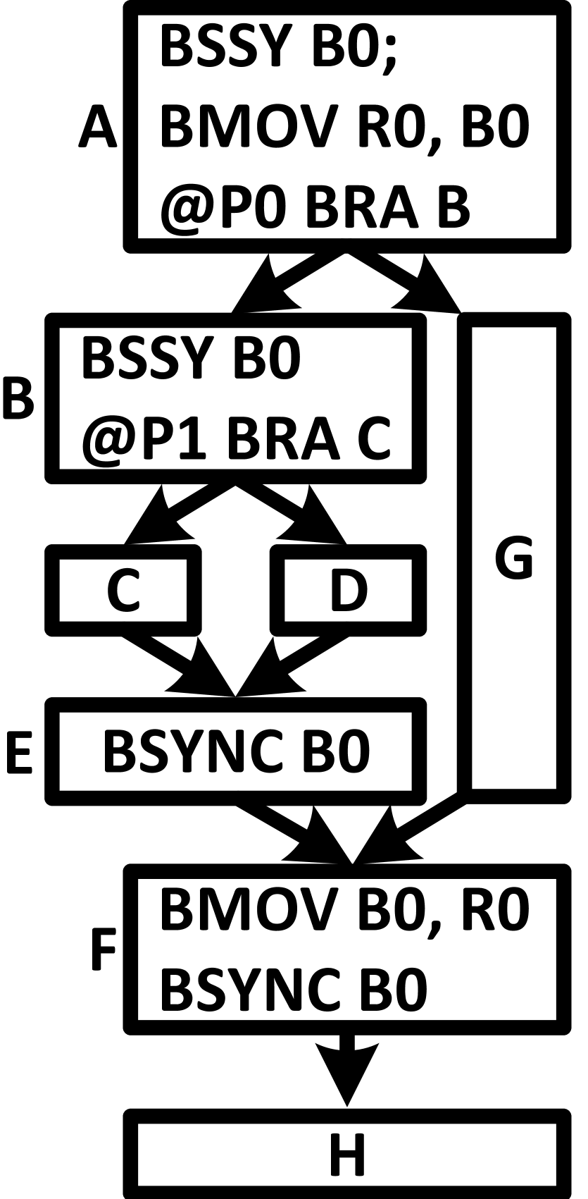
Figure 3 shows BSSY, BSYNC, and BMOV instructions in a sample program with two nested thread divergences. The control flow graph of this program is depicted in Figure 3(a), and how a sample warp updates registers during the execution is represented in Figure 3(b). Basic blocks in the control flow graph may have many more instructions, but we only show the control flow instructions and their correct order within basic blocks. By means of multiple experiments, we observed that all active threads executing BMOV instructions read or write the same value in Rx registers. Therefore, in this figure, we only represent the Rx value for one of the active threads executing the BMOV instruction. We show a dead value in a register by a dashed line. In this example, reconvergence is enforced at BSYNC instructions, and the taken path is prioritized after branch divergence. We observed that, NVIDIA prioritizes the path most threads follow, but this is just an optimization. NVIDIA’s compiler generates a binary whose correct execution does not depend on which path, taken or not-taken, will be prioritized in runtime by the control flow management mechanism.
In this example, B0 is used in two BSYNC instructions: one in E that reconverges Threads 2 and 3, and another in F that reunites all threads. Each BSYNC instruction requires a BSSY instruction to initialize the B0 register with the reconvergence mask. The BSYNC in F needs a BSSY in A that initializes B0 with 1111 ( ), while the BSYNC in E requires a BSSY in B that initializes B0 with 1100 ( ). Since B is executed after A, it overwrites the value in B0. This value, the reconvergence mask, is needed later in F to reconverge all threads. To avoid losing this value when B is executed, a BMOV in A copies B0 to R0 ( ). The value remains in R0 until the BSYNC in F requires it. Before that, a BMOV in F retrieves this value from R0 and writes it back to B0 ( , ). This example illustrates how BMOV uses the R0 register as a backup for the B0 register in this nested thread divergence scenario. By doing this, NVIDIA avoids increasing the number of Bx registers needed to handle the worst possible nesting scenario. NVIDIA’s compiler inserts BMOV instructions in the program to spill Bx values to Rx registers if there are not enough Bx registers available.
VI-B Reconvergence Earlier than IPDom
Reconvergence using a BSYNC instruction has the advantage of allowing for reconvergence earlier or later than the IPDom point. Reconverging earlier can enhance the performance of some programs with unstructured control flow. However, in scenarios where reconvergence occurs earlier than the IPDom, incorrect use of control-flow instructions can lead to a deadlock. This deadlock may occur because an early reconvergence point is not an IPDom point where all diverged threads must pass through before finishing. In other words, some diverged threads may never reach an early reconvergence point, hence, waiting for them at the reconvergence point can cause a deadlock.
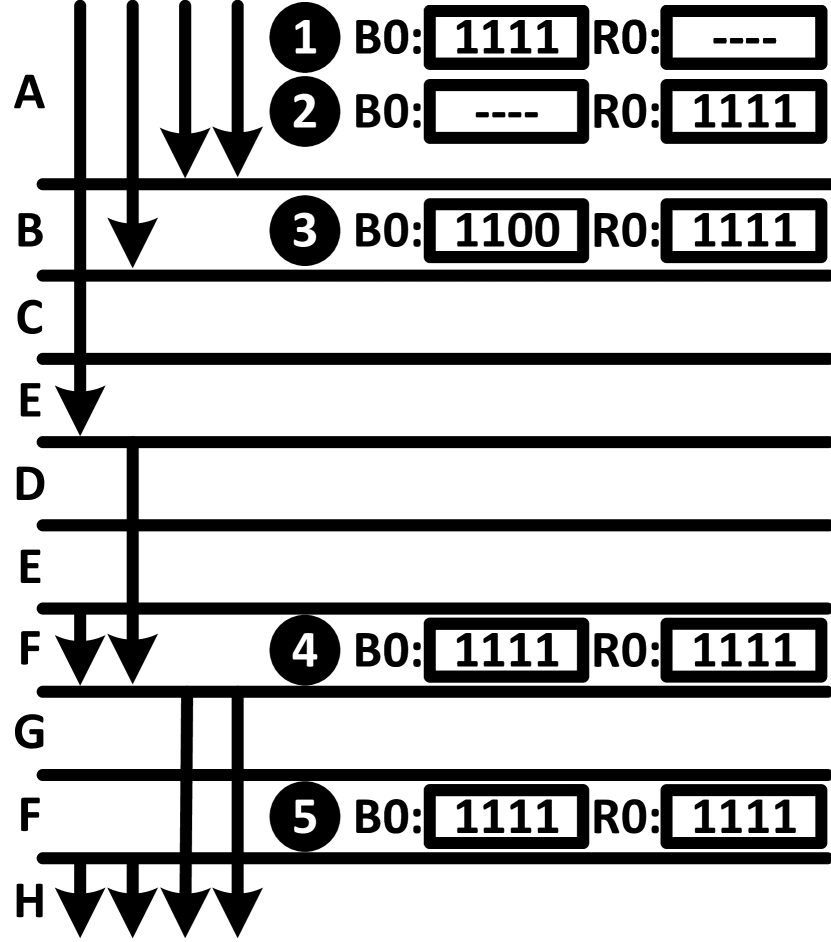
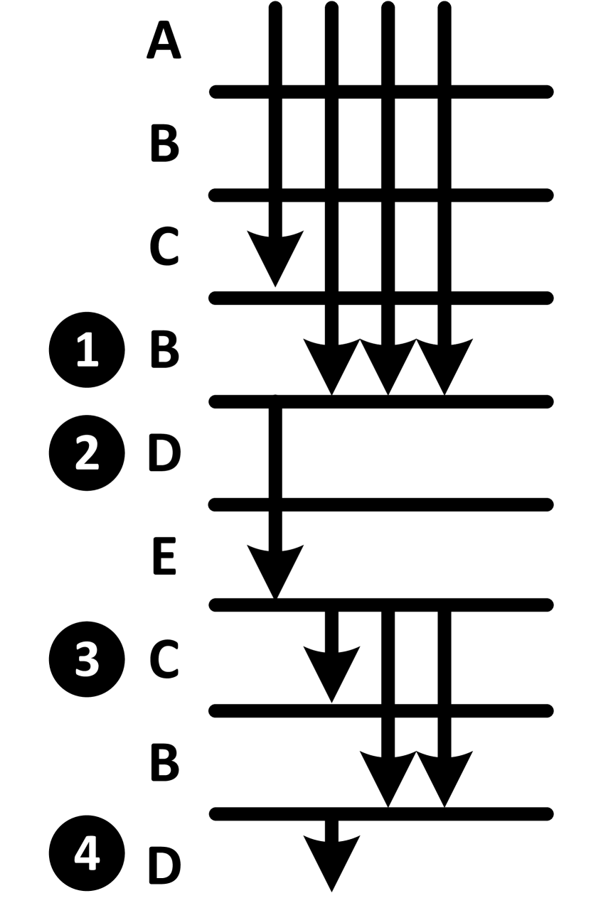
Figure 4 illustrates a sample program where early reconvergence is possible. Figure 4(a) depicts the program’s control flow graph, while Figure 4(b) shows register updates during the execution of a single warp. Although each basic block may contain many more instructions, we display only the control-flow instructions for simplicity. NVIDIA’s compiler inserts the control-flow instructions within each basic block in the same order as shown in the figure. We assume the taken path is executed before the not-taken path, and threads within a warp are reconverged after BSYNC instructions.
In this example, D is the IPDom point for A because this is the earliest point that all threads in the warp pass through it before finishing. However, thread 0 never passes through B after the divergence in A and executes C, D, and E before finishing. Therefore, B cannot be an IPDom point for A, as all diverged threads must pass through the IPDom point by definition. However, B serves as an early reconvergence point for threads 1, 2, and 3 of the warp since all of them can be reunited at this point before executing D.
This example contains two BSYNC instructions to reconverge threads within a warp that diverge after A: one is inserted in B and the other in D. These BSYNC instructions read their reconvergence masks from B0 and B1, which are initialized in A before the divergence. Two BSSY instructions in A initialize B0 and B1 to 1111 since all threads of the warp execute the BSSY instructions together ( ). If the value in B0 does not change, this program will never finish due to a deadlock. The deadlock happens because B0 contains 1111 and is used by BSYNC in B, which means all threads of the warp must reconverge after B. However, thread 0 in the warp never executes B. Therefore, all other threads of the warp waiting for thread 0 to execute B would be blocked forever.
To solve this problem, a BREAK instruction is inserted in C. The BREAK removes all threads in C whose P1 is false from the reconvergence mask in B0. These threads will diverge to D after executing the branch instruction in C and will never execute B again. In this example, we assumed only thread 0 has a false P1 when executing the BREAK in C. Removing thread 0 from B0 changes its value to 1110 in B0, which is the reconvergence mask in B ( ). Therefore, only threads 1, 2, and 3 are reunited after B ( ), and they never wait for thread 0. Thread 0 joins them after D ( ), where the program does not have any divergence afterward. This example shows that if we add BREAK in C, early reconvergence is enforced in B, and the program finishes correctly without any deadlock. This example emphasizes that the compiler can assist the control flow management mechanism in reuniting threads earlier than the IPDom points by simply inserting the control-flow instructions in the right locations in the program.
VI-C Spinlock Implementation

A CUDA spinlock implementation, as shown in Figure LABEL:fig:pre_volta_deadlock, causes a well-known SIMT-induced deadlock in pre-Volta GPUs due to two constraints: 1) pre-Volta GPUs enforce reconvergence at the IPDom points, and 2) they execute diverged paths serially, one after another (more details in section III). Turing prevents this deadlock by removing these constraints with the compiler’s help. The compiler does not place BSYNC at the IPDom point if it causes a deadlock and also inserts YIELD to switch to a sibling path when executing the same path would lead to a deadlock.
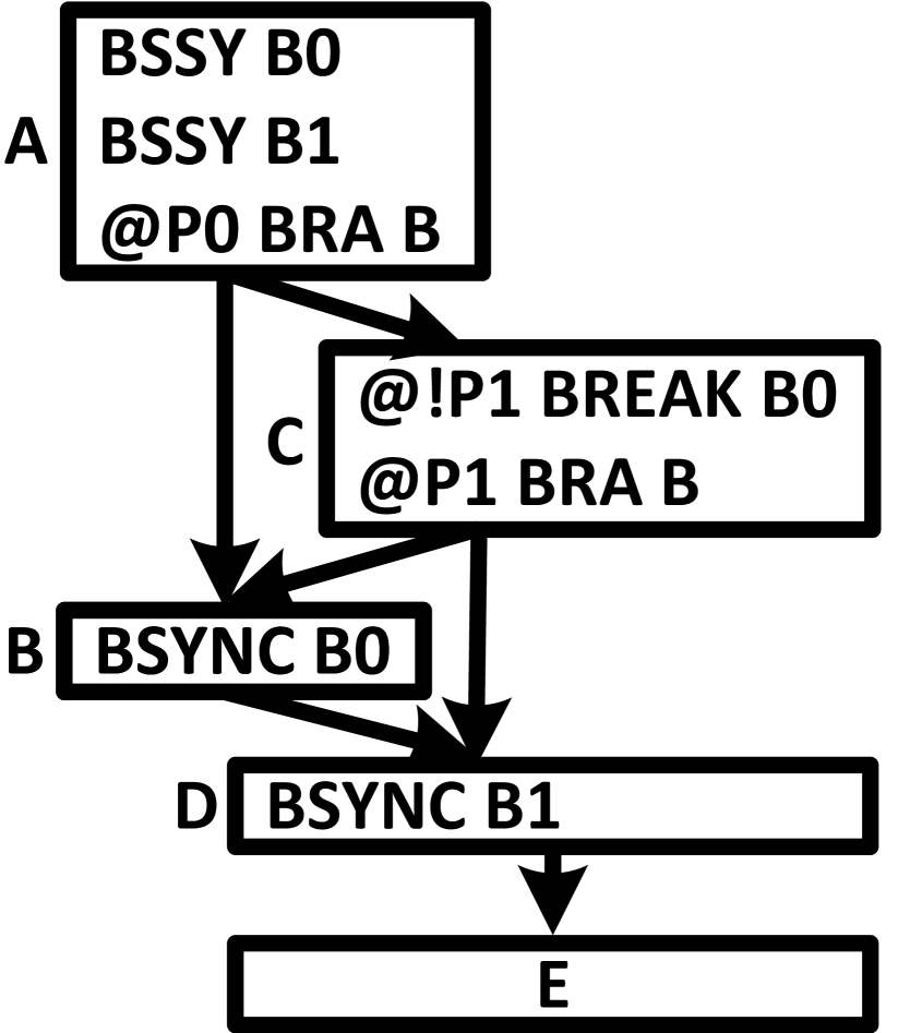
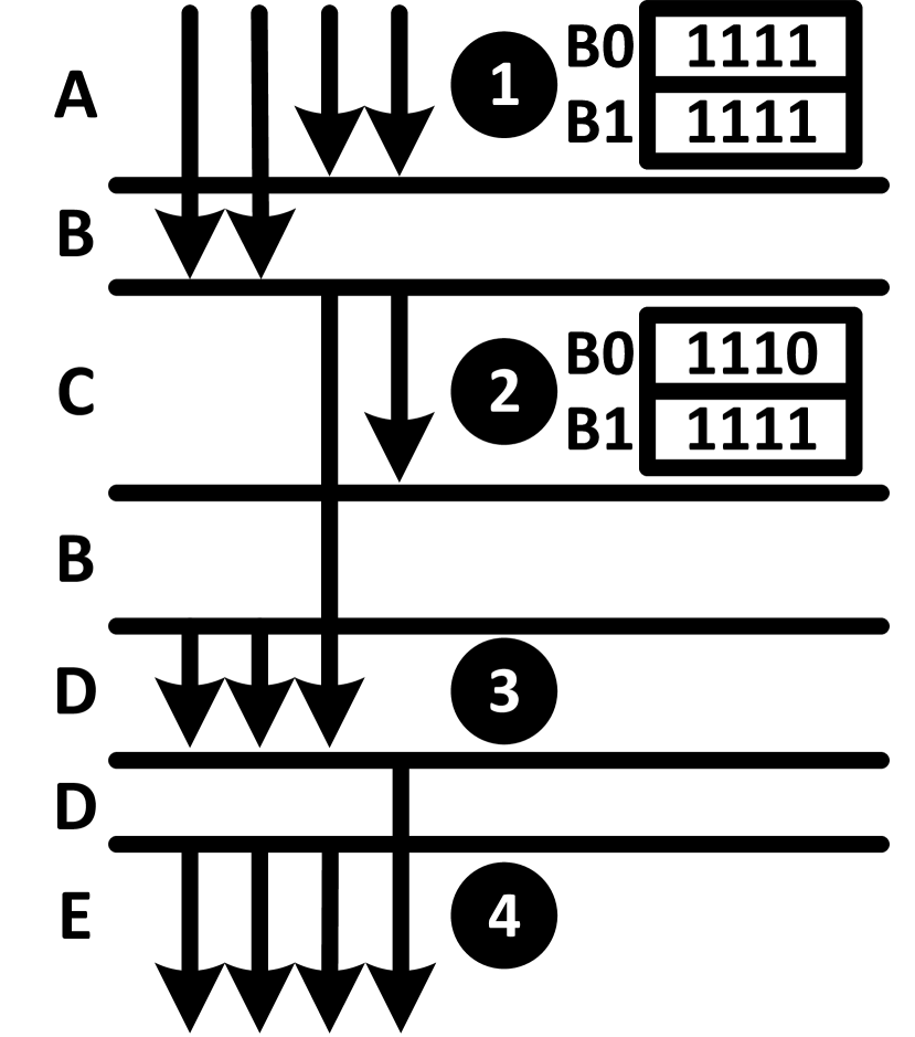
Figure 5 illustrates the crucial role of BSYNC and YIELD in preventing deadlock in the spinlock implementation depicted in Figure LABEL:fig:pre_volta_deadlock. Figure 5(a) shows the control-flow graph of this implementation augmented with Turing’s control-flow instructions. Figure 5(b) illustrates a possible execution by a sample warp, assuming the taken path is executed before the not-taken path after divergence. Before the taken path finishes, YIELD intervenes and switches execution to the not-taken path. The YIELD is necessary to avoid deadlock we observed that if we remove it from the binary of the program, its execution never finishes.
This program contains a critical section in D, right after a loop. Within the loop, threads compete to acquire a lock and get permission to execute the critical section. Only one of them acquires the lock and sets P0 to true when executing C. This thread diverges from the other threads in its warp and exits the loop to execute the critical section. After the critical section, it releases the lock and allows another thread to acquire the lock and enter the critical section.
In this example, thread 3 acquires the lock and diverges from the other threads in the warp but does not execute the critical section immediately because the taken path has higher priority and must be executed first. Hence, threads 0, 1, and 2 jump to the beginning of the loop and execute the YIELD ( ). If this YIELD did not exist, these threads could never acquire the lock because thread 3 still holds it. Therefore, these threads would be trapped in the loop forever. However, the YIELD solves this issue and switches the execution to D ( ), the sibling path. Thread 3 executes the critical section in D and releases the lock. Then, it executes the BSYNC in E, which is used to reconverge all threads. After that, thread 3 remains blocked until all other threads execute this BSYNC. In this scenario, all other threads continue execution from C ( ), the next instruction after YIELD. This time, one of them can acquire the lock because thread 3 has already released it. In this example, thread 2 acquires the lock and executes the critical section ( ).
If the BSYNC in E was placed before releasing the lock, it would also cause a deadlock. The deadlock would happen because the thread that has the lock waits infinitely to reconverge with other threads in the warp, but the other threads are stuck in the loop because none of them can acquire the lock and exit the loop. In this program, the IPDom point is right after the branch, which is before releasing the lock. Therefore, after detecting the deadlock scenario, NVIDIA’s compiler decides to put BSYNC later than the IPDom point in E after the lock was released.
VII Hanoi Microarchitecture
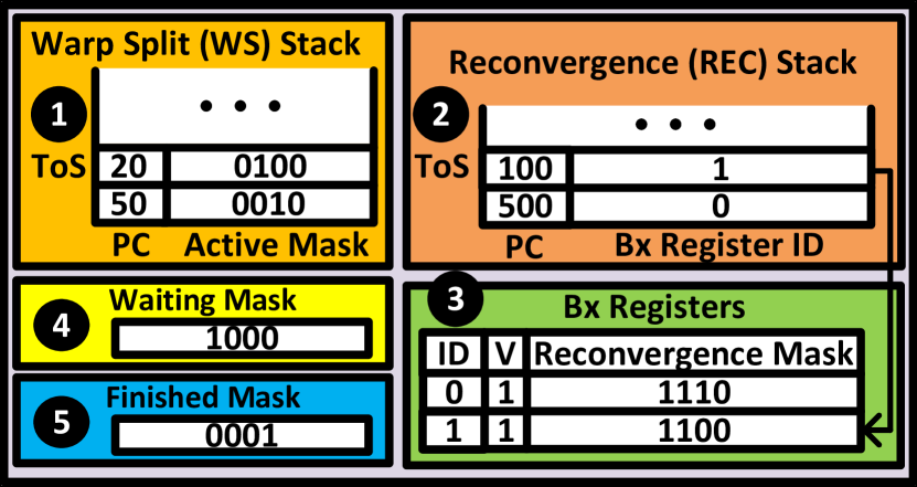
Figure 6 illustrates our proposed design called Hanoi for a control flow management mechanism in Turing. This design comprises two stacks: the Warp Split (WS) ( ) and Reconvergence (REC) ( ) stacks. It also includes a few Bx registers ( ) and two masks: the waiting ( ) and finished ( ) masks.
The WS stack has one entry per path to be executed, each containing a PC and an active mask. The paths in the WS stack are executed in the stack order, and the entry at the top of the stack corresponds to the path currently in execution. The active mask indicates which threads in the warp are following this path, while the PC specifies the next instruction these threads must execute. In this figure, thread 2 in the warp is set to execute instruction 20 in one path, and thread 1 is set to execute instruction 50 in another path.
The REC stack has one entry per reconvergence point, each containing a PC and a Bx register ID. The reconvergences occur with their order in the REC stack. The entry at the top of the stack corresponds to the path currently in execution. The PC points to the instruction that threads must execute after reconvergence, and the Bx register ID refers to the Bx register containing the reconvergence mask. The reconvergence mask indicates which threads in the warp must reunite at this reconvergence point. A Bx register only contains a valid reconvergence mask when its valid (V) bit is set to 1. This figure shows two reconvergence points: one at PC 100 and the other at PC 500. The entry in the REC stack for the reconvergence point at PC 100 refers to B1, which contains the reconvergence mask indicating that threads 2 and 3 must reconverge at this point. The entry for the reconvergence at PC 500 refers to B0, containing a reconvergence mask indicating that threads 2 and 3 must join thread 1 at this point.
The waiting mask indicates which threads are waiting at the current reconvergence point (i.e., the one at the top of the REC stack). In this figure, thread 3 has already reached its reconvergence point at PC 100. The finished mask tracks which threads have executed the EXIT instruction and are already finished. In this figure, thread 0 has already finished.
VII-A Managing Bx Registers
A BSSY instruction initializes Bx registers. It uses the Bx register ID in its operands to address a specific Bx register. The Bx register is initialized with the active threads in the warp executing the BSSY instruction. These threads are exactly the ones indicated in the active mask of the top entry in the WS stack. Hence, when BSSY is executed, this active mask is copied to the specified Bx register, and its valid bit is set to 1.
A BREAK instruction updates a Bx register. It addresses a Bx register by its ID and removes specific threads from the reconvergence mask stored within it. This update is possible because reconvergence points in the REC stack read their reconvergence masks from Bx registers. In other words, they indirectly refer to a Bx register containing their reconvergence mask. If the reconvergence mask were stored directly in the REC entries, removing threads from the reconvergence mask of an entry not at the top of the stack would be impossible.
A BMOV instruction transfers Bx registers to Rx registers or vice versa. When a BMOV instruction moves a Bx register to an Rx register, it invalidates the Bx register. Upon returning the value to the Bx register, its valid bit is set to 1 again. BMOV instructions are used for sharing Bx registers among different reconvergence points. In other words, multiple entries in the REC stack may refer to the same Bx register. However, an entry only reads a Bx register when it is at the top of the REC stack. Therefore, a BMOV instruction can move a value from a Bx register to an Rx register, provided the value is moved back before the reconvergence point which needs this value becomes the top entry in the REC stack and this reconvergence point is reached in the program.
An EXIT instruction completes the execution for threads. Once an EXIT instruction is executed, Hanoi removes finished threads from all Bx registers and adds them to the finished mask. Finished threads in this mask must be removed from any reconvergence mask read from Rx registers before it is written to Bx registers. This step is necessary to ensure correct control flow, as some threads might have already finished while a reconvergence mask was stored in the Rx.
When a reconvergence occurs, the reconvergence mask for the reconvergence point, which is in a Bx register, is no longer needed. Therefore, the Bx register containing the reconvergence mask is invalidated.
VII-B Managing REC Stack
When reconvergence occurs, Hanoi pops the top entry from the REC stack, retrieves the reconvergence mask from its Bx register, and pushes a new entry into the WS stack. This new entry contains the PC and reconvergence mask from the top entry of the REC stack. Thus, execution continues from the instruction after the reconvergence point for all threads in the reconvergence mask.
Hanoi uses the waiting mask to determine when it must reconverge threads, which is crucial for the correct traversal of the control flow graph during execution. Before scheduling the top entry of the WS stack, Hanoi checks if the reconvergence mask of the top entry in the REC stack is valid and fully appears in the waiting mask. If it does, all threads in the reconvergence mask have reached the reconvergence point, and it is time to reconverge them. Hanoi never reconverges threads if the Bx register of the top entry in the REC stack is invalid since this Bx register might have been overwritten and used by another reconvergence point.
Hanoi uses the REC stack for reconvergence at BSYNC or WARPSYNC instructions. While both instructions reconverge threads within a warp, they have significant differences that require different handling.
Before each BSYNC instruction, there is a corresponding BSSY instruction that specifies the reconvergence PC and the ID of the Bx register holding the reconvergence mask. After executing BSSY, Hanoi pushes an entry onto the REC stack with the specified reconvergence PC and Bx register ID.
In contrast, WARPSYNC has no prior instruction like BSSY and lacks a Bx operand. For WARPSYNC, Hanoi must allocate an empty Bx register and initialize it with the reconvergence mask. We assume an empty Bx register is always available; if not, the compiler can spill them to Rx registers using BMOV instructions. The PC of the instruction following WARPSYNC becomes the reconvergence PC in its REC stack entry, as this is where threads continue execution after reconvergence. The reconvergence PC and the ID of the allocated Bx register form the entry pushed to the REC stack for a WARPSYNC instruction. However, this is done only for the first subset of threads in the reconvergence mask executing the WARPSYNC instruction. This entry is already on the REC stack for other subsets, so Hanoi does not push it again.
Having a separate stack for tracking reconvergence points, the REC stack, allows for efficient handling of WARPSYNC instructions in Hanoi, as described above. Supporting WARPSYNC instructions is either impossible or highly inefficient in alternative mechanisms that use only one stack. This is because, in mechanisms using a single stack, it is crucial to specify the reconvergence point before divergence happens to update the stack correctly and reconverge threads at that point. However, when a WARPSYNC is executed, we only know that threads might have diverged somewhere before WARPSYNC, without knowing exactly where. Hence, it is not possible or inefficient to update the stack so that reconvergence occurs correctly when the WARPSYNC is executed.
VII-C Managing WS Stack
Hanoi may push or pop entries onto the WS stack due to BSYNC, WARPSYNC, EXIT, BRA, and YIELD instructions. For other instructions, only the PC for the top entry in the WS stack needs to be updated. Some instructions, such as CALL and RET, change the PC to jump to or return from a function. However, incrementing the PC to point to the following instruction is sufficient for most instructions.
A BRA instruction may cause thread divergence, resulting in two entries being pushed: one for the taken path and another for the not-taken path. Our observations indicate that the path followed by the majority of threads is executed first, so Hanoi pushes this path after the other one.
An entry must be popped when a path finishes. A path is considered finished when BSYNC, WARPSYNC, or EXIT instructions are executed. After executing BSYNC or WARPSYNC, Hanoi pops the entry and adds its active threads to the waiting mask. However, for EXIT instruction, an entry is popped from the WS stack only when all threads in the path execute the EXIT. Some threads may be predicated off and do not execute EXIT. For them, the instruction following the EXIT will be executed in the next cycle. Hanoi adds threads executing EXIT to the finished mask.
Hanoi switches to a sibling path when a YIELD instruction is executed, provided a sibling exists. Switching to a non-sibling path generates a wrong control flow. If a sibling path exists, its entry is immediately below the top entry in the WS stack. Therefore, upon executing a YIELD instruction, Hanoi simply swaps the top two entries in the WS stack to switch to the sibling path. However, a path may have an entry below it that does not belong to its sibling. Paths are siblings only if they share a common reconvergence point, which is always represented by the top entry in the REC stack. Hence, to determine if the top two paths of the WS stack are siblings, Hanoi compares the union of their active mask with the reconvergence mask of the entry at the top of the REC stack. If this union is a subset of the reconvergence mask, the paths are siblings; otherwise, they are not. For example, in Figure 6, threads 1 and 2 are in the top two entries in the WS stack. However, these two paths are not siblings because the reconvergence mask for the top entry in the REC stack does not include thread 1. Therefore, executing a YIELD instruction does not switch to any other path and behaves like a NOP.
VIII Methodology
| Rodinia |
|---|
| B+tree (BTR), Backprop (BKPR), BFS (RBFS), dwt2d (DWT), Gaussian (GAUS), Hotspot (HOTS), Kmeans (KMNS), LUD, NN, NW, Particlefilter_Float (PARF), Particlefilter_Naive (PARN), Pathfinder (PFN), SRAD, lavaMD (LAVA) |
| ISPASS |
| AES, BFS, LIB, LPS, NN, NQU, STO, WP |
| Lonestar |
| BFS (LBFS), BFS-Atomic (BFSA), BFS-WLC (BFSW), DMR, NSP, SSSP |
| GraphBIG |
| Betweenness_Centr (BETC), BFS_Topo_Thread_Centric (BFST), BFS_Data_Warp_Centric (BFSD), BFS_Topo_Unroll (BFSU), Connected_Comp (CC), Degree_Centr (DC), Kcore (KCOR), SSSP_Topo_Thread_Centric (SSTT), Triangle_Count (TC) |
| Tango |
| AlexNet (AN), GRU, LSTM |
| #SMs | 30 |
|---|---|
| #Threads/Warps per SM | 1024 / 32 |
| #sub-cores per SM | 4 |
| RF size per SM | 256KB |
| #Issue Schedulers per SM | 4 |
| Issue Scheduling Policy | GTO |
| L2 size | 3MB |
| L1/Shared Memory per SM | 64KB |
We utilized NVIDIA tools to generate the native assembly source code (SASS), control flow graph (CFG), and traces for a large variety of well-known benchmarks, summarized in Table II. Specifically, we used cuobjdump [28] for SASS code generation, nvdisasm [28] for CFG generation, and NVBit [37] for trace generation. For some benchmarks, different input data sets were used, indicated by a number in front of their names throughout this paper. Through thorough analysis of these benchmarks, we identified patterns, scenarios, and use cases illustrating how control-flow instructions are defined, utilized, and handled by the control-flow management mechanism in Turing GPUs. This analysis allowed us to formulate a set of rational and intuitive hypotheses regarding the semantics of the control-flow instructions and detailed policies of the control flow management mechanism in Turing.
Subsequently, we developed a checker program to validate our hypotheses. We created parsers for the CFG, SASS code, and traces. After parsing these files, we loaded them into the checker, which verified whether any of our hypotheses were violated in the traces obtained from the actual hardware. For example, when our hypothesis is that interleaving happens only after a YIELD instruction and in the traces interleaving happens at some other point, it would be a violation. If a violation occurred, a log file was generated to provide insights into the cause of the violation. We then refined our hypotheses and repeated the process. Our objective was to develop a set of hypotheses that are never violated across all benchmarks, thereby explaining the semantics of the control flow instructions and the detailed policies employed in the Turing control flow management mechanism.
Given that NVIDIA uses runtime heuristics, it is extremely challenging to discover and incorporate all of them into our hypotheses set. However, we managed to uncover many of them, making our design, Hanoi, work very close to Turing’s design. To gauge our proximity, we designed Hanoi based on our hypotheses and generated its control flow trace. We then compared this trace to Turing’s trace and fine-tuned our design to minimize any discrepancies. To evaluate the impact of these discrepancies on performance, we used Hanoi’s traces in a well-known trace-driven simulator called Accel-Sim [19] and compared the measured performance with the baseline using Turing’s traces. For our performance simulations, we utilized the configuration of the NVIDIA RTX 2060, as detailed in Table III.
IX Evaluation
We developed a set of assumptions about the semantics of control-flow instructions and the detailed policies used in Turing’s control flow management mechanism. Based on these assumptions, we designed Hanoi and refined both the assumptions and the design to closely match Turing’s architecture, to end up with the designed described in section 6.
To evaluate how close Hanoi is to Turing’s design, we compared their control flow traces. A control flow trace shows the sequence of instructions each warp executes from the program’s start to end. If a specific warp has an identical control flow trace in both Hanoi and Turing, it means that both designs executed exactly the same threads of the warp together at every cycle. However, significant differences in the sequences do not necessarily indicate substantial differences in the designs. A minor change such as prioritizing the taken path over the not-taken path after a branch divergence, can result in a significantly different control flow trace.
The control flow trace is essentially a sequence of instructions. To compare them, we used the Levenshtein distance [21], which measures the minimum number of insertions, deletions, or updates needed to transform one trace into the other. We divided this distance by the size of the trace to compute a metric showing the percentage discrepancy between the two traces.
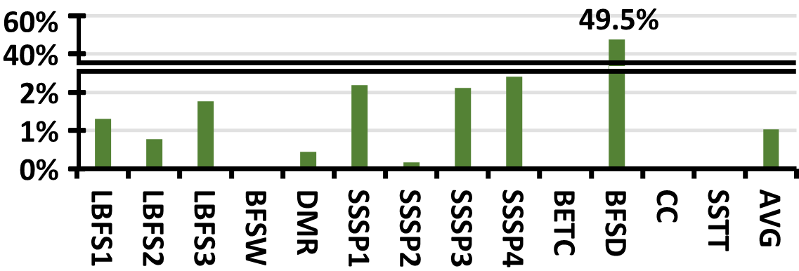
We analyzed 59 program executions: 41 different benchmarks and 18 that were some of this benchmarks varying input data. Among these 59, 46 produced a 0% discrepancy, indicating that Hanoi and Turing generated exactly the same control flow trace. The discrepancies for the remaining executions are depicted in Figure 8. Except for BFSD, all benchmarks exhibit negligible discrepancy percentages below 2.4%, with an average discrepancy of just 1%. The high discrepancy for BFSD (49.5%) is due to a runtime heuristic in Turing that Hanoi does not support. Hanoi enforces reconvergence at all BSYNC instructions, while Turing in some rare occasions ignores these reconvergences for performance reasons.
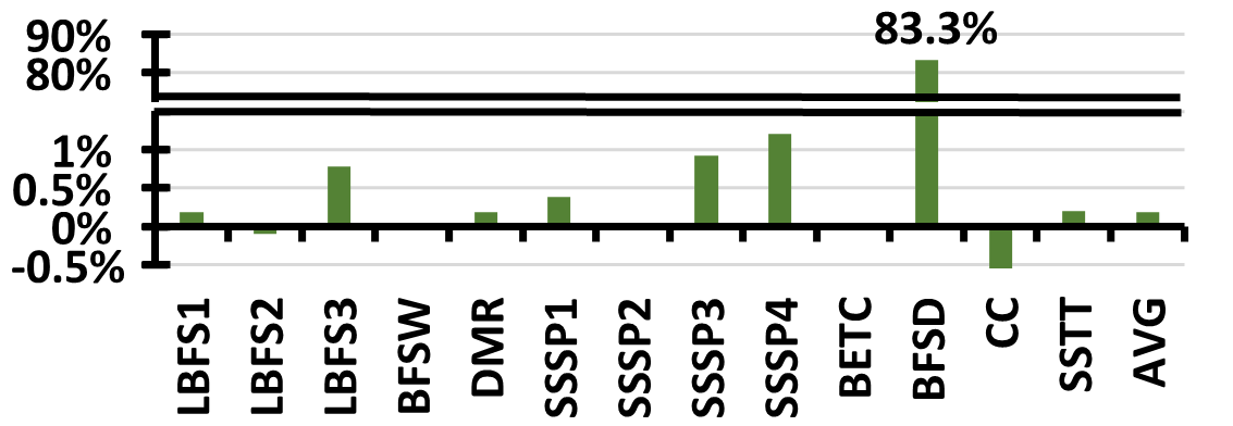
Figure 8 shows the impact of these discrepancies on performance. We computed the relative IPC difference between Hanoi and Turing. On average, this difference is 0.2%, which is negligible. Except for BFSD, all other benchmarks show a performance impact below 1.2%. BFSD, however, exhibits an 83.3% performance gain in Hanoi. This gain results from Hanoi’s enforcement of reconvergence at all BSYNC instructions, which improved SIMD unit utilization by 31.9%, leading to a significant performance improvement.
IX-A Hardware Overhead
Hanoi is a lightweight scheme that is seamlessly integrated into the GPU’s pipeline, as shown in Figure LABEL:fig:SIMT_Core. It does not require an increase in the I-Buffer size or significant overhead in the scoreboard. The scoreboard only needs to be extended to track the dependencies between a few Bx registers. The WS stack in Hanoi requires a maximum of 32 entries to support the scenario where all 32 threads of a warp diverge. In this case, the REC stack needs 31 entries to reconverge these threads. Managing WS and REC stacks has also low-cost since they are managed as stacks. Each entry in the WS stack is just a PC and a 32-bit mask, making it simpler than the SIMT-Stack, which requires a reconvergence PC on top of these fields. While the SIMT-Stack compares the reconvergence PC with the PC to identify when to pop an entry, Hanoi pops an entry when WARPSYNC, BSYNC, or EXIT is executed. Each entry in the REC stack is also very cost-effective; it consists of just a PC and an index to a Bx register. Since Bx registers can be shared among REC entries, only a few of them are needed. For example, in a system with 8 Bx registers, 3 bits for indexing is sufficient. The waiting and finished masks are also only 32-bit masks. Overall, the total storage required by Hanoi for a design with 8 x registers is 432 bytes, which is negligible and almost 43% less storage than that needed for a SIMT-Stack.
X Related Work
GPU vendors such as NVIDIA have never fully disclosed their control flow management mechanisms. However, they have revealed some aspects in early publications [23] and documents [33]. Researchers have discovered more details through microbenchmarking [38], leading to the widespread acceptance of a SIMT-Stack [39, 14] design as the baseline. Based on this, researchers developed performance simulators such as GPGPU-Sim [3, 1], which execute PTX [30] instructions, sufficient for early GPUs and traditional workloads. However, simulating modern workloads that use closed-source libraries like cuDNN [5] and cuBLAS [32] in PTX is impossible. To address this, researchers developed trace-driven simulators such as Accel-Sim [19] that support SASS [28] instructions.
Accel-Sim relies on traces for control flow and does not model the functionality of the control flow mechanisms due to insufficient details for modern GPUs like Volta [31]. Volta introduced a new feature called Independent Thread Scheduling [10, 31], resulting in considerable changes to NVIDIA’s execution model, suggesting substantial changes in control flow management mechanisms. Despite this, public information is unavailable, and researchers who have demystified modern GPUs such as Volta [18] and Turing [17] have not disclosed details of this mechanism.
To the best of our knowledge, this work is the first to describe the semantics of the control-flow instructions encountered in modern NVIDIA GPU binaries and propose an implementation of a control-flow mechanism that supports them, Hanoi. Supporting these instructions required significant differences in Hanoi’s microarchitecture compared to other alternatives in the literature.
For example, Hanoi executes one path and can switch to its sibling after a YIELD instruction. This software-controlled interleaving requires simple hardware and provides a more predictable control flow that can be leveraged to optimize other components in the GPU. Other proposals support interleaving, but they all employ fine-grained interleaving during runtime, requiring much more complex hardware. DWS [25] needs a table and a path scheduler instead of the WS stack in Hanoi. Unlike Hanoi, it ignores some reconvergence points and attempts to reconverge warp splits having the same PC during runtime. It is sensitive to the path scheduling policy, and the opportunity for reconvergence might be missed. Dual-Path [35] addresses this issue by extending SIMT-Stack entries to store two active paths in each entry. At any cycle, any of the two paths on top of stacks can be scheduled. However, this scheme cannot support BREAK and WARPSYNC because BREAK needs to modify the reconvergence mask, which may not be at the top of the stack, and WARPSYNC lacks a prior instruction like BSSY to know when to push on top of the stack for reconvergence. Multi-Path (MP) [12] allows scheduling any path but requires I-Buffer slots and scoreboards per path, which is a huge cost avoided in Hanoi. Warp splits and reconvergence points must also be stored in a random access memory and content addressable memory instead of the two stacks used in Hanoi. Furthermore, it does not propose any mechanism to support WARPSYNC, YIELD, BREAK and EXIT. AWARE [11] avoids some costs of MP but still does not propose any mechanism for these unsupported instructions. Subwarp interleaving [8] has a considerably different design than Hanoi and supports fine-grained interleaving. However, the authors state that the significant cost of this scheme did not justify its benefits for a commercial product. This is not the case for Hanoi; it is designed based on real hardware traces and is lightweight and cost-effective.
Hanoi is a much more lightweight scheme compared to other alternatives. It is the first design to store reconvergence masks in Bx registers. These Bx registers can be modified to support BREAK instructions. They can be transferred to Rx registers and shared among reconvergence points. The compiler manages the transfers, keeping the hardware simple. Sharing Bx registers also reduces the cost of storing metadata needed for reconverging threads. Hanoi is the first design that does not require storing a reconvergence PC per path and per reconvergence point unlike all other alternative designs [14, 25, 35, 39, 13, 11, 12, 27]. It also does not need to store pending masks per reconvergence point similar to MP or AWARE. Instead, it leverages compiler assistance and uses simpler hardware mechanisms to reconverge threads.
Other proposals that can schedule threads from different warps [14, 13, 27] are completely different from Hanoi, which only schedules threads within a warp. Other proposed mechanisms for reconverging threads at points other than the IPDom points are mechanisms sensitive to path scheduling policies [9, 12, 25], or they use profiling [13] or oracle information [14]. Hanoi uses BREAK and other control flow instructions to guarantee earlier reconvergence when possible. We do not know how the compiler inserts these instructions, but this mechanism is highly similar to speculative reconvergence [7] in the literature. Delaying the reconvergences when there is a chance for deadlock has already been proposed [11], but it is different in Hanoi. Unlike this previous proposal, Hanoi relies on the use of YIELD instructions to avoid deadlock. We have experimentally observed that this is how modern NVIDIA GPUs operate, although we do not know the detailed algorithms that NVIDIA’s compiler uses to detect or insert these instructions.
XI Conclusion
In this work, we uncovered the semantics of control-flow instructions in the SASS ISA and detailed policies used in Turing’s control-flow management mechanism. To achieve this goal, we used the information in the traces and binaries of commonly used benchmarks. Based on our findings and verified assumptions, we designed a control flow management mechanism for Turing called Hanoi. Hanoi is cost-effective and generates a control flow trace that is highly similar to Turing. The discrepancy percentage between the control flow traces of Hanoi and Turing is 1% on average, which leads to less than 0.2% relative IPC difference for a large set of diverse benchmarks.
References
- [1] T. M. Aamodt, W. W. Fung, and T. H. Hetherington, “Inside volta: The world’s most advanced data center gpu,” http://gpgpu-sim.org/manual/index.php/Main_Page.
- [2] baidu, “Deepbench: Benchmarking deep learning operations on different hardware,” https://github.com/baidu-research/DeepBench, 2020.
- [3] A. Bakhoda, G. L. Yuan, W. W. L. Fung, H. Wong, and T. M. Aamodt, “Analyzing cuda workloads using a detailed gpu simulator,” in International Symposium on Performance Analysis of Systems and Software (ISPASS), 2009.
- [4] A. Betts, N. Chong, A. Donaldson, S. Qadeer, and P. Thomson, “Gpuverify: a verifier for gpu kernels,” in International Conference on Object Oriented Programming Systems Languages and Applications (OOPSLA), ser. OOPSLA ’12. New York, NY, USA: Association for Computing Machinery, 2012, p. 113–132.
- [5] S. Chetlur, C. Woolley, P. Vandermersch, J. Cohen, J. Tran, B. Catanzaro, and E. Shelhamer, “cudnn: Efficient primitives for deep learning,” 2014.
- [6] K. D. Cooper and L. Torczon, Engineering a compiler. Morgan Kaufmann, 2022.
- [7] S. Damani, D. R. Johnson, M. Stephenson, S. W. Keckler, E. Yan, M. McKeown, and O. Giroux, “Speculative reconvergence for improved simt efficiency,” in Proceedings of the 18th ACM/IEEE International Symposium on Code Generation and Optimization. Association for Computing Machinery, 2020.
- [8] S. Damani, M. Stephenson, R. Rangan, D. Johnson, R. Kulkami, and S. W. Keckler, “Gpu subwarp interleaving,” in International Symposium on High-Performance Computer Architecture (HPCA), 2022.
- [9] G. Diamos, B. Ashbaugh, S. Maiyuran, A. Kerr, H. Wu, and S. Yalamanchili, “Simd re-convergence at thread frontiers,” in International Symposium on Microarchitecture (MICRO), 2011.
- [10] L. Durant, O. Giroux, M. Harris, and N. Stam, “Inside volta: The world’s most advanced data center gpu,” https://developer.nvidia.com/blog/inside-volta/, 2017.
- [11] A. ElTantawy and T. M. Aamodt, “Mimd synchronization on simt architectures,” in International Symposium on Microarchitecture (MICRO), 2016.
- [12] A. ElTantawy, J. W. Ma, M. O’Connor, and T. M. Aamodt, “A scalable multi-path microarchitecture for efficient gpu control flow,” in International Symposium on High Performance Computer Architecture (HPCA), 2014.
- [13] W. W. L. Fung and T. M. Aamodt, “Thread block compaction for efficient simt control flow,” in International Symposium on High Performance Computer Architecture (HPCA), 2011.
- [14] W. W. Fung, I. Sham, G. Yuan, and T. M. Aamodt, “Dynamic warp formation and scheduling for efficient gpu control flow,” in International Symposium on Microarchitecture (MICRO), 2007.
- [15] A. Habermaier and A. Knapp, “On the correctness of the simt execution model of gpus,” in Programming Languages and Systems, H. Seidl, Ed. Berlin, Heidelberg: Springer Berlin Heidelberg, 2012, pp. 316–335.
- [16] H. Jeon, G. S. Ravi, N. S. Kim, and M. Annavaram, “Gpu register file virtualization,” in International Symposium on Microarchitecture (MICRO), 2015.
- [17] Z. Jia, M. Maggioni, J. Smith, and D. P. Scarpazza, “Dissecting the nvidia turing t4 gpu via microbenchmarking,” 2019.
- [18] Z. Jia, M. Maggioni, B. Staiger, and D. P. Scarpazza, “Dissecting the nvidia volta gpu architecture via microbenchmarking,” arXiv preprint arXiv:1804.06826, 2018.
- [19] M. Khairy, Z. Shen, T. M. Aamodt, and T. G. Rogers, “Accel-sim: An extensible simulation framework for validated gpu modeling,” in International Symposium on Computer Architecture (ISCA), 2020.
- [20] C. Lattner and V. Adve, “Llvm: A compilation framework for lifelong program analysis & transformation,” in International symposium on code generation and optimization (CGO), 2004.
- [21] V. I. Levenshtein et al., “Binary codes capable of correcting deletions, insertions, and reversals,” in Soviet physics doklady, vol. 10, no. 8. Soviet Union, 1966, pp. 707–710.
- [22] G. Li, P. Li, G. Sawaya, G. Gopalakrishnan, I. Ghosh, and S. P. Rajan, “Gklee: concolic verification and test generation for gpus,” SIGPLAN Not., vol. 47, no. 8, p. 215–224, feb 2012.
- [23] E. Lindholm, J. Nickolls, S. Oberman, and J. Montrym, “Nvidia tesla: A unified graphics and computing architecture,” in IEEE Micro, vol. 28, no. 2, 2008, pp. 39–55.
- [24] P. Mattson, C. Cheng, G. Diamos, C. Coleman, P. Micikevicius, D. Patterson, H. Tang, G.-Y. Wei, P. Bailis, V. Bittorf et al., “Mlperf training benchmark,” Proceedings of Machine Learning and Systems, vol. 2, pp. 336–349, 2020.
- [25] J. Meng, D. Tarjan, and K. Skadron, “Dynamic warp subdivision for integrated branch and memory divergence tolerance,” in international symposium on Computer architecture (ISCA), 2010.
- [26] L. Nai, Y. Xia, I. G. Tanase, H. Kim, and C.-Y. Lin, “Graphbig: understanding graph computing in the context of industrial solutions,” in International Conference for High Performance Computing, Networking, Storage and Analysis (SC), 2015.
- [27] V. Narasiman, M. Shebanow, C. J. Lee, R. Miftakhutdinov, O. Mutlu, and Y. N. Patt, “Improving gpu performance via large warps and two-level warp scheduling,” in International Symposium on Microarchitecture (MICRO), 2011.
- [28] NVIDIA, “Cuda binary utilities,” https://docs.nvidia.com/cuda/cuda-binary-utilities/index.html.
- [29] NVIDIA, “Nvidia turing gpu architecture,” https://images.nvidia.com/aem-dam/en-zz/Solutions/design-visualization/technologies/turing-architecture/NVIDIA-Turing-Architecture-Whitepaper.pdf.
- [30] NVIDIA, “Parallel thread execution isa,” https://docs.nvidia.com/cuda/parallel-thread-execution/index.html.
- [31] NVIDIA, “Nvidia tesla v100 gpu architecture,” https://images.nvidia.com/content/volta-architecture/pdf/volta-architecture-whitepaper.pdf, 2017.
- [32] NVIDIA, “cublas,” https://docs.nvidia.com/cuda/cublas/index.html, 2024.
- [33] NVIDIA, “Cuda c++ programming guide,” 2024.
- [34] V. J. Reddi, C. Cheng, D. Kanter, P. Mattson, G. Schmuelling, C.-J. Wu, B. Anderson, M. Breughe, M. Charlebois, W. Chou, R. Chukka, C. Coleman, S. Davis, P. Deng, G. Diamos, J. Duke, D. Fick, J. S. Gardner, I. Hubara, S. Idgunji, T. B. Jablin, J. Jiao, T. S. John, P. Kanwar, D. Lee, J. Liao, A. Lokhmotov, F. Massa, P. Meng, P. Micikevicius, C. Osborne, G. Pekhimenko, A. T. R. Rajan, D. Sequeira, A. Sirasao, F. Sun, H. Tang, M. Thomson, F. Wei, E. Wu, L. Xu, K. Yamada, B. Yu, G. Yuan, A. Zhong, P. Zhang, and Y. Zhou, “Mlperf inference benchmark,” in International Symposium on Computer Architecture (ISCA), 2020.
- [35] M. Rhu and M. Erez, “The dual-path execution model for efficient gpu control flow,” in International Symposium on High Performance Computer Architecture (HPCA), 2013.
- [36] T. G. Rogers, M. O’Connor, and T. M. Aamodt, “Cache-conscious wavefront scheduling,” in International Symposium on Microarchitecture (MICRO), 2012.
- [37] O. Villa, M. Stephenson, D. Nellans, and S. W. Keckler, “Nvbit: A dynamic binary instrumentation framework for nvidia gpus,” in International Symposium on Microarchitecture (MICRO), 2019.
- [38] H. Wong, M.-M. Papadopoulou, M. Sadooghi-Alvandi, and A. Moshovos, “Demystifying gpu microarchitecture through microbenchmarking,” in International Symposium on Performance Analysis of Systems & Software (ISPASS), 2010.
- [39] S. Woop, J. Schmittler, and P. Slusallek, “Rpu: a programmable ray processing unit for realtime ray tracing,” ACM Trans. Graph., vol. 24, no. 3, p. 434–444, jul 2005.