Distributed Quantum Computing across an Optical Network Link
Abstract
\AcDQC combines the computing power of multiple networked quantum processing modules, enabling the execution of large quantum circuits without compromising on performance and connectivity 1, 2. Photonic networks are well-suited as a versatile and reconfigurable interconnect layer for distributed quantum computing (DQC); remote entanglement shared between matter qubits across the network enables all-to-all logical connectivity via quantum gate teleportation (QGT) 3, 4. For a scalable DQC architecture, the QGT implementation must be deterministic and repeatable; until now, there has been no demonstration satisfying these requirements. We experimentally demonstrate the distribution of quantum computations between two photonically interconnected trapped-ion modules. The modules are separated by , and each contains dedicated network and circuit qubits. By using heralded remote entanglement between the network qubits, we deterministically teleport a controlled-Z gate between two circuit qubits in separate modules, achieving fidelity. We then execute Grover’s search algorithm 5 – the first implementation of a distributed quantum algorithm comprising multiple non-local two-qubit gates – and measure a success rate. Furthermore, we implement distributed iSWAP and SWAP circuits, compiled with 2 and 3 instances of QGT, respectively, demonstrating the ability to distribute arbitrary two-qubit operations 6. As photons can be interfaced with a variety of systems, this technique has applications extending beyond trapped-ion quantum computers, providing a viable pathway towards large-scale quantum computing for a range of physical platforms.
I Introduction
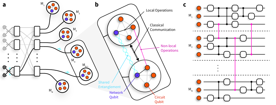
The potential of quantum computing to revolutionise various fields ranging from cryptography to drug discovery is widely recognised 7, 8. However, regardless of the physical platform used to realise the quantum computer, scaling up the number of qubits while maintaining precise control and inter-connectivity is a major technical challenge 9, 10, 11. The DQC architecture, depicted in Fig. 1, addresses this challenge by enabling large quantum computations to be executed by a network of quantum processing modules 1, 2. The modules each host a relatively small number of qubits and are interconnected via both classical and quantum information channels. By preserving the reduced complexity of the individual modules and transforming the scaling challenge into the task of building more modules and establishing an interface between them, the DQC architecture provides a scalable approach to fault-tolerant quantum computing 3, 4.
The interface between modules could be realised by directly transferring quantum information between modules. However, losses in the interconnecting quantum channels would lead to the unrecoverable loss of quantum information. Quantum teleportation offers a loss-less alternative interface, using only bipartite entanglement (e.g. Bell states) shared between modules, together with local operations and classical communication (LOCC) to effectively replace the direct transfer of quantum information across quantum channels 12, 13. \AcQGT efficiently implements non-local entangling gates between qubits in separate modules, consuming only one Bell pair and the exchange of two classical bits 14, 15, as depicted in Fig. 1(b). Given arbitrary single- and two-qubit operations within each node, QGT completes a universal gate set for the distributed quantum computer 13. The primary advantage of teleportation-based schemes over direct transfer is the exclusive use of the quantum channel for generating identical Bell states; channel losses can be overcome by repetition without losing quantum information, and the distance between modules can be increased by inserting quantum repeaters 16. Additionally, channel noise may be suppressed using entanglement purification 17. Since teleportation protocols are executed strictly after entanglement has been established, they enable continuous deterministic operation even if the entanglement is generated non-deterministically. This deterministic nature is crucial for the scalability, eliminating the need for post-selection of singular successful outcomes out of an exponentially large set of undesired outcomes.
Teleportation protocols are agnostic to the physical implementation of the quantum channels, making them a versatile tool for DQC across different platforms. In the trapped-ion quantum charge-coupled device (QCCD) architecture, qubits can be dynamically transported between modules within a single chip 18 – or even across chips 19 – and thus be used to mediate entangling gates between different trap zones 20, 21. Photons, however, make natural carriers of quantum information since they can travel long distances without significant degradation of their quantum state. Photonic interconnects enable all-to-all connectivity between qubits distributed across the network whose topology can be dynamically reconfigured without the need to open up complex vacuum and/or cryogenic systems. Moreover, optical components are widely available and can be operated under ambient conditions. These properties make photonic interconnects particularly appealing for networking quantum computing modules, as shown in Fig. 1(a). As depicted in Fig. 1(b), we consider modules containing “network” and “circuit” qubits with full interconnectivity via local quantum operations. Remote entanglement of network qubits in separate modules is generated by the interference of photons, where reconfigurability and flexibility could be provided via a photonic switchboard. This entanglement can then be used to mediate entangling gates between the circuit qubits in different modules via QGT, enabling the network to function as a single fully connected quantum processor, as shown in Fig. 1(c). Heralded entanglement between spatially separated qubits has been achieved experimentally in a variety of platforms including diamond colour centres 22, 23, superconducting qubits 24, neutral atoms 25, 26, and trapped-ions 27, 28, 29.
QGT has been implemented probabilistically in purely photonic systems, requiring passive optical elements and post-selection to perform the conditional rotations that complete the gate teleportation 30, 31. Chou et al.32 demonstrated deterministic teleportation of a controlled-NOT gate between two qubits encoded in the modes of two superconducting cavities on the same device, separated by , while a third cavity enabled the deterministic generation of entanglement between two transmon network qubits. Recently, there have been demonstrations of QGT between superconducting qubits within a single device, demonstrating the viability of QGT to overcome nearest neighbour constraints in this architecture 33, 34. In the trapped-ion QCCD architecture, Wan et al.20 demonstrated QGT in which the entanglement was deterministically generated between two “network” qubits via local operations before being transported to two separate locations within the same trap. Daiss et al.35 demonstrated a heralded non-local entangling gate across a photonic quantum network using a photon to directly transfer quantum information between modules. However, photon loss necessarily destroys the states of the circuit qubits, rendering this scheme non-deterministic. Until now, there has been (i) no demonstration of deterministic QGT across a quantum network, and (ii) no demonstration of distributed circuits comprising multiple non-local entangling gates. In photonic platforms, this has been prevented by the inability to store the photons between interactions 30, 31, while in the QCCD demonstration, this was limited by the decoherence of the circuit qubits during the generation of entanglement 20.
In this work, we present the first demonstration of DQC across a network of two trapped-ion modules, each containing a network qubit and a circuit qubit, and separated by a macroscopic distance ( ). We mediate deterministic two-qubit CZ interactions between the circuit qubits via QGT, utilizing entanglement previously established across the network between the two network qubits. Leveraging the robust storage of quantum information in the circuit qubits while generating subsequent rounds of entanglement between network qubits 36, we execute distributed quantum circuits comprising multiple non-local two-qubit gates. We demonstrate the distributed iSWAP and SWAP gates, which consist of 2 and 3 instances of QGT, respectively. The actions of all teleported gates are characterized using quantum process tomography (QPT). Finally, we implement Grover’s algorithm on our distributed quantum computer.
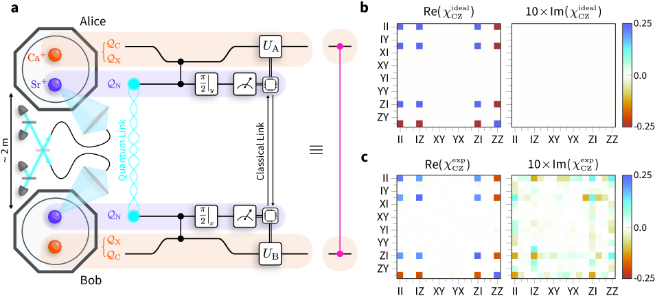
II Teleportation of a Controlled-Z Gate
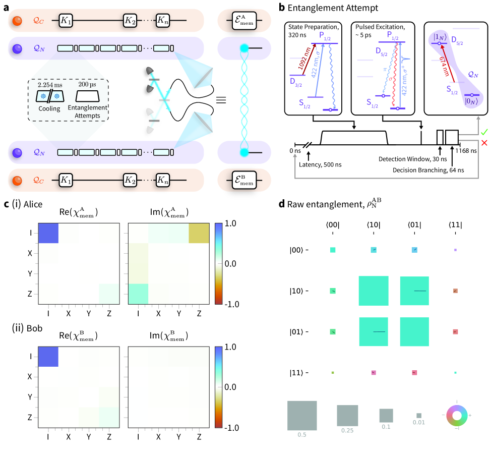
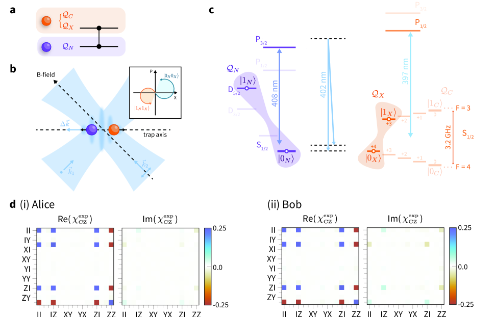
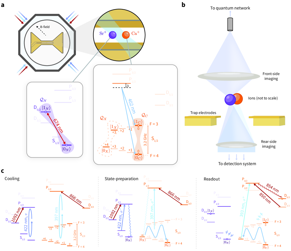
Our apparatus, depicted in Fig. 2(a), consists of two trapped-ion modules, Alice and Bob, each co-trapping one 88Sr+ ion and one 43Ca+ ion (Methods). The Ca+ ion provides a magnetic field-insensitive “circuit” qubit, , in the ground hyperfine manifold which has been used to demonstrate state-of-the-art quantum logic 37, 38. The Sr+ ion, on the other hand, provides an efficient interface to the optical quantum network 28. We define the network qubit in Sr+ by . To implement local entangling operations between these two species, we employ the light shift gate mechanism 39 between and an auxiliary qubit in the ground hyperfine manifold of Ca+, , which, unlike the qubit, experiences the necessary light shifts (Methods). At the points at which we want to perform the local entangling gate, we transfer the quantum information stored in temporarily to to perform the gate operations (Methods).
The QGT protocol used here to mediate CZ gates between the circuit qubits in separate modules is depicted in Fig. 2. We allow the circuit qubits to start in an arbitrary state , which could be part of a larger, long-running computation. We begin the QGT protocol by generating the remotely entangled Bell state,
between the network qubits 28, with a fidelity of (Methods). This is done via a try-until-success process, where a herald indicates a success. The circuit qubits provide a robust quantum memory 36, enabling storage of the encoded quantum information until the remote entanglement is successfully heralded. At this stage, we map the state stored in the circuit qubits () to the auxiliary qubits () in preparation for the local entangling operations (Methods). In each module, we perform local CZ gates between the network and auxiliary qubits (Methods), before transferring the auxiliary qubit back to the circuit qubit. We then perform mid-circuit measurements of the network qubits in the and bases in Alice and Bob, respectively. The modules exchange the measurement outcomes in real-time – using a classical (TTL) link between their control systems – and perform single-qubit feed-forward operations conditioned on the exchanged bits to complete the gate teleportation protocol (Methods). This implements the non-local gate .
We characterise the QGT protocol using QPT to reconstruct the process matrix, , providing a complete description of the action of the teleported CZ gate on the two circuit qubits. Compared to the ideal CZ process, shown in Fig. 2(b), the reconstructed process matrix for the teleported gate, shown in Fig. 2(c), has an average gate fidelity of . The QGT protocol is completely self-contained – the input states of the circuit qubits are set prior to the execution of the non-local gate – and output states are available for further computation. With single-qubit rotations of the circuit qubits, this teleported CZ gate is a key element of a gate set for DQC, enabling the modules to act as a single, fully-connected universal quantum processor.
III Distributed Quantum Computing
In general, any arbitrary two-qubit unitary operation can be decomposed into at most three CZ gates 6. We demonstrate our ability to perform sequential rounds of QGT by executing the CZ decompositions of the iSWAP and SWAP gates, shown in Figs. 3(a)(i) and 3(b)(i), comprising two and three instances of QGT, respectively. As with the teleported CZ, we characterise these circuits via QPT, see Figs. 3(a)(ii) and 3(b)(ii). From the reconstructed process matrices, we measure average gate fidelities of and for the iSWAP and SWAP gates, respectively. By constructing circuits with multiple instances of QGT – enabled by our ability to perform QGT deterministically and on-demand – we demonstrate the ability to perform universal DQC.
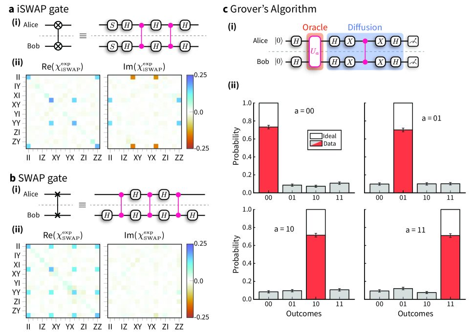
Finally, we implement Grover’s algorithm 5 on our distributed quantum processor. This algorithm considers searching through a set of unsorted items, , to find a particular item, . The search problem is represented by the function
In the two-qubit case, there are four items to search through. Classically, the item could be identified with, on average, two queries of the function . Using the quantum circuit shown in Fig. 3(c)(i), the same task can be accomplished with only one query. After preparing a superposition of all possible inputs with parallel Hadamard gates, an instance of QGT implements the oracle, which performs the mapping , marking the state . A second instance of QGT implements the Grover diffusion circuit, which decodes the quantum information provided by the oracle into an observable. In the two-qubit case considered here, the application of the Grover diffusion circuit should leave the register in the state , which is the solution to the function , and thus a measurement of the register yields the solution to the search problem with unit probability. In the case of items, to approach unit probability of obtaining the solution, one would require iterations of the oracle-diffusion circuit, compared with for a classical search.
The results of Grover’s algorithm – executed on our distributed quantum processor – are shown in Fig. 3(c)(ii). For the marked states , we obtain the correct result with an average success rate of . To our knowledge, this represents the first deterministic execution of any algorithm on a distributed quantum computer.
IV Discussion
The performance of our distributed quantum circuits is consistent with the errors from the teleported CZ gates. We summarise the leading error sources affecting our teleported CZ gate in Table 1. The measured fidelity of our gate is slightly lower than that predicted by the error budget, which we attribute to drifts in the calibration of various components over the duration of the data acquisition. The majority of identified error sources occur during local operations in each module. It is worth noting that our local errors do not represent the state-of-the-art of trapped-ion processors; however, local operations exceeding the fidelity threshold for fault-tolerant quantum computing have been demonstrated in this platform 38, 39, 40, 41, 42. Relevant to our implementation, Hughes et al.39 demonstrated mixed-species two-qubit gates between 88Sr+ and 43Ca+ ions with a gate error of . We therefore conclude that the technical limitations in our implementation can be overcome. The other significant source of error is the remote entanglement of the network qubits across the photonic quantum network; we observe a fidelity of the remotely entangled network qubits to the desired state of . Unlike the local operations, the performance of our remote entanglement is at the state-of-the-art. To improve this, and hence enable the teleportation of high-fidelity entangling gates between modules, entanglement purification could be used to distribute high-fidelity entangled states from a number of lower-fidelity entangled states 17, 43.
Our implementation features a single circuit qubit in each module; however processors with larger numbers of qubits have been realised. With only 3 circuit qubits (and one network qubit) per module, the purification of arbitrary quantum channels would be possible 43. The capabilities of the individual modules may be extended even further by deploying the QCCD architecture. With recent demonstrations in both academic research 44 and industry 21 highlighting the power of this approach, embedding these systems in a quantum network would combine their power with the reconfigurability and flexibility of the DQC architecture. Conversely, computational bottlenecks associated with ion transport overheads observed in the QCCD architecture 21 could be mitigated using photonic interconnects integrated into a single device 45.
While the results presented here were achieved using trapped-ion quantum processing modules, photons may be interfaced with a variety of systems. The connectivity and reconfigurability enabled by photonic networks provides a scalable approach for other quantum computing platforms such as diamond colour centres and neutral atoms. Additionally, modules of different platforms could be connected via wavelength conversion, enabling a hybrid DQC platform. Furthermore, teleportation protocols are not limited to qubits; they can be extended to higher-dimensional quantum computing paradigms, such as qudits 46 and continuous-variable quantum computing (CVQC) 47, 48, allowing these platforms to benefit from the DQC architecture. Quantum repeater technology 16 would enable large physical separation between the quantum processing modules, thereby paving the way for the development of a quantum internet 49. The scope of these networks extends beyond quantum computing technologies; the ability to control distributed quantum systems, as enabled by this architecture, to engineer complex quantum resources has applications in multi-partite secrete sharing 50, metrology 51, and probing fundamental physics 52.
V Methods
V.1 Dual-species ion-trap modules
Our apparatus comprises two trapped-ion processing modules, Alice and Bob. Each module, depicted in Ext. Fig. 1, consists of an ultra-high vacuum chamber containing a room-temperature, micro-fabricated surface Paul trap; the trap used in Alice (Bob) is a HOA2 53 (Phoenix 54) trap, fabricated by Sandia National Laboratories. In each module, we co-trap 88Sr+ and 43Ca+ ions. Each species of ion is addressed via a set of lasers used for cooling, state-preparation, and readout. A high-numerical aperture (0.6 NA) lens enables single-photon collection from the Sr+ ions. A magnetic field is applied parallel to the surface of the trap to provide a quantisation axis.
As outlined in the main text, the Sr+ ion provides an optical network qubit, , which is manipulated directly using a laser. The ground hyperfine manifold of the Ca+ ion provides a circuit qubit, . At , the sensitivity of the qubit transition frequency to magnetic field fluctuations is , i.e. orders of magnitude lower than that of the qubit – making it an excellent memory for quantum information 36. Additionally, we define an auxiliary qubit, , in the ground hyperfine manifold of Ca+ for implementing local entangling operations, state preparation, and readout. The measured state-preparation and measurement (SPAM) errors for each qubit are presented in Ext. Fig. 2.
The spectral isolation between the two species allows us to address one species without causing decoherence of the quantum information encoded in the other species. We make use of this for sympathetic cooling, mid-circuit measurement, and interfacing with the quantum network during circuits.
V.2 Quantum process tomography
The action of a quantum process acting on a system of qubits may be represented by the process matrix such that,
where are the set of single-qubit Pauli operators , and . \AcQPT enables us to reconstruct the matrix , thereby attaining a complete characterisation of the process.
QPT is performed by preparing the qubits in the states , where are chosen from a tomographically complete set
| (1) |
performing the process, , followed by measuring the output state in a basis chosen from a tomographically complete set. Using diluted maximum-likelihood estimation 55, the outcomes of the measurements can be used to reconstruct the -matrix representing the process. In practice, the input states are created by rotating to with
| (2) |
Likewise, the tomographic measurements are performed by rotating the output state by [Eq. (2)], and subsequently measuring it in the basis. Ideally, this sequence implements the projectors and , where . However, SPAM errors would manifest as errors in the reconstructed process; we therefore model these errors by replacing the measurement with positive-operator-valued measures,
where () is the SPAM error associated with the () qubit state. The values used for these operators are given in Ext. Fig. 2.
Resampling of the measurement outcomes is used to generate new data sets, which are analysed in the same way as the original data set, and are used to determine the sensitivity of the analysis to the statistical fluctuations in the input data. Error bars on the fidelities of reconstructed processes are quoted as the standard deviation of the fidelities of the resampled data sets.
V.3 Remote entanglement generation
The heralded generation of remote entanglement between network qubits in separate modules, outlined in Stephenson et al.28, is central to our QGT protocol. Photons entangled with the Sr+ ions are collected from each module using high-numerical aperture lenses and single-mode optical fibres bring the photons to a central Bell state analyser, where a measurement of the photons projects the ions into a maximally entangled state. This forms the photonic quantum channel interconnecting the two modules. Following Stephenson et al.28, we use a -pulse to map the remote entanglement from the ground-state Zeeman qubit to an optical qubit, which we refer to as the network qubit, to minimise the number of quadrupole pulses in subsequent operations. Successful generation of entanglement is heralded by particular detector click patterns and, after subsequent local rotations, indicates the creation of the maximally entangled Bell-state,
This process is executed while simultaneously storing quantum information in the circuit qubits which, as demonstrated by Drmota et al.36, are robust to this network activity.
Each entanglement generation attempt takes and it takes attempts to successfully herald entanglement on average, corresponding to a success probability of . To mitigate heating of the ion-crystal, we interleave of entanglement generation attempts with of sympathetic re-cooling of the Sr+-Ca+ crystal using the Sr+ ion. The sympathetic recooling comprises of Doppler cooling, followed by of electromagnetically-induced transparency (EIT) cooling. Overall, this results in an average entanglement generation rate of (equivalently, it takes on average to generate entanglement between network qubits), although this rate could be increased by optimising the interleaved cooling sequence. This rate is lower than the rate previously reported in our apparatus 28 due to the additional cooling. We characterise the remote entanglement using quantum state tomography; by performing tomographic measurements on copies of the remotely entangled state, we reconstruct the density matrix of the network qubits, , shown in Ext. Fig. 3(d). In order to isolate the fidelity of the “Quantum Link” in Fig. 2, we account for the imperfect tomographic measurements in the reconstruction of the density matrix. The fidelity of the reconstructed state to the desired Bell-state, given by , is .
V.4 Circuit qubit memory during entanglement generation
Since each instance of QGT requires the generation of entanglement between network qubits, it is necessary to ensure that the circuit qubits preserve their encoded quantum information during this process. Due to their low sensitivity to magnetic field fluctuations, the circuit qubits have exhibited coherence times, and in previous work we demonstrated these qubits to be robust to network activity 36. We further suppress dephasing through dynamical decoupling. Typically, dynamical decoupling is implemented over a fixed period of time; however the success of the entanglement generation process is non-deterministic and would therefore leave the dynamical decoupling sequence incomplete.
One solution would be to complete the dynamical decoupling pulse sequence once the entanglement has been generated, however it is desirable to minimise the time between heralding the entanglement generation and performing the QGT protocol, in order to prevent dephasing of the network qubits. Instead, we make use of the fact that the action of a dynamical decoupling pulse on one of the circuit qubits can be propagated through the teleported CZ gate as
| (3) |
We therefore perform the dynamical decoupling pulses on the circuit qubits until we obtain a herald of remote entanglement, at which point we immediately perform the QGT sequence – implementing a CZ gate on the state of the circuit qubits at the point of interruption. Once this gate is completed, we perform the remaining dynamical decoupling pulses (without any inter-pulse delay), and use (3) to apply the appropriate rotations required to correct for the propagation through the CZ gate. With this method, we suppress the dephasing errors in the circuit qubits during entanglement generation, while minimising the time between successfully heralding the entanglement and consuming it for QGT.
We deploy Knill dynamical decoupling 56, 57 with a inter-pulse delay (corresponding to a pulse every three rounds of interleaved entanglement attempts and re-cooling). We use QPT to reconstruct the process of storing the quantum information while generating entanglement; ideally, this process would not alter the quantum information stored in the circuit qubit. \AcQPT is implemented by choosing input states for the circuit qubits from the tomographically complete set given in (1), generating remote entanglement between the network qubits while dynamically decoupling the circuit qubits, then upon successful herald, completing the dynamical decoupling sequence and performing tomographic measurements of the circuit qubits. The reconstructed process matrices for each module corresponding to the action of storing quantum information during entanglement generation are shown in Ext. Fig. 3(c). We observe fidelities to the ideal operation of and for Alice and Bob, respectively.
V.5 Local mixed-species entangling gates
The ability to perform logical entangling gates between ions of different species allows us to separate the roles of network and circuit ions. We implement mixed-species entangling gates following the approach taken by Hughes et al.39, in which geometric phase gates are deterministically executed using a single pair of Raman beams, as depicted in Ext. Fig. 4. Here, we apply the gate mechanism directly to the network qubit in Sr+ – rather than the Zeeman ground state qubit, as done in Hughes et al.39 and Drmota et al.36 – at the cost of a slightly reduced gate efficiency that is compensated for by the use of higher laser powers. This enables us to perform mixed-species CZ gates between the network and auxiliary qubits. We characterise our mixed-species entangling gates using QPT in each module, reconstructing the process matrices representing the action of the local CZ gate acting between the network and auxiliary qubits. The reconstructed process matrices for each module are shown in Ext. Fig. 4(d). Compared to the ideal CZ gate, we observe average gate fidelities of and for Alice and Bob, respectively.
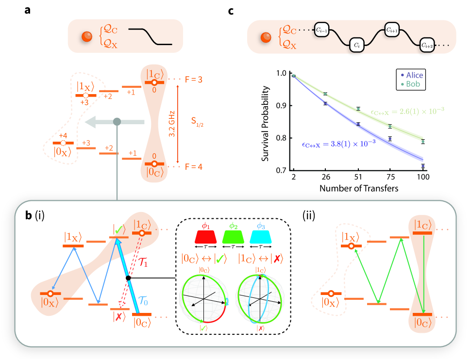
V.6 Hyperfine qubit transfer
Since the circuit qubit does not participate in the mixed-species gate, the gate interaction is performed on the network and auxiliary qubits. Consequently, we require the ability to map coherently between the circuit and auxiliary qubit before and after the local operations. As shown in Ext. Fig. 5, this mapping is performed using a pair of Raman beams detuned by , to coherently drive the transitions within the ground hyperfine manifold of Ca+.
The transfer of the circuit qubit to the auxiliary qubit begins with the mapping of the state to the state . However, due to the near degeneracy of the transition and the transition (see Ext. Fig. 5), separated by only , it is not possible to map the state out of the circuit qubit without off-resonantly driving population out of the state. We suppress this off-resonant excitation using a composite pulse sequence, shown in Ext. Fig. 5(b)(i), comprising three pulses resonant with the transition, with pulse durations equal to the -time of the transition, and phases optimised to minimise the off-resonant excitation. This pulse sequence allows us to simultaneously perform a -pulse on the transition and the identity on the off-resonantly-driven transition. Raman -pulses are then used to complete the mapping to the state. Another sequence of Raman -pulses coherently maps , thereby completing the transfer of the circuit qubit to the auxiliary qubit, . To implement the mapping , the same pulse sequence is applied in reverse.
We characterise our mapping sequence by performing a modification of single-qubit randomised benchmarking (RBM), in which we alternate Clifford operations on the and qubits, as illustrated in Ext. Fig. 5(c). We assume that (i) the single-qubit gate errors for the and qubits are negligible compared to the transfer infidelity (we typically observe single-qubit gate errors for the Ca+ hyperfine qubits), and (ii) the fidelity of the transfer is similar to . We therefore we model the survival probability as
where is the number of hyperfine transfers, accounts for SPAM error offsets, and is the depolarising probability for the transfer, related to the error per transfer as
The RBM results are shown in Ext. Fig. 5(c); we measure an error per transfer of () for Alice (Bob).
V.7 Conditional Operations
To complete the QGT protocol, the two modules perform mid-circuit measurements of the network qubits, exchange the measurement outcomes, and apply a local rotation of their circuit qubits conditioned on the outcomes of the measurements. By virtue of the spectral isolation between the two species of ions, mid-circuit measurements of the network qubits can be made without affecting the quantum state of the circuit qubits. The mid-circuit measurement outcomes, , are exchanged in real-time via a classical communication channel between the modules – in our demonstration, this is a TTL link connecting the control systems of the two modules. Following the exchange of the measurement outcomes, the modules, Alice and Bob, perform the conditional rotations and , respectively, where
where .
Errors in the mid-circuit measurements of the network qubits will result in the application of the wrong conditional rotation; effectively, this would appear as a joint phase-flip of the circuit qubits following the teleported gate. The mid-circuit measurement errors arise from the non-ideal single-qubit rotation of the network qubit to map the measurement basis onto the computational basis, and errors due to the fluorescence detection of the network qubit. Using RBM, we measure single-qubit gate errors for the network qubits of and for Alice and Bob, respectively. The error in the fluorescence detection is estimated from the observed photon scattering rates of states, in addition to the lifetime of the state 58. We choose a mid-circuit measurement duration of ; we estimate fluorescence detection errors of and for Alice and Bob, respectively. Combining these error mechanisms, we estimate contributions to the teleported CZ gate error of and for Alice and Bob, respectively.
- DQC
- distributed quantum computing
- QGT
- quantum gate teleportation
- QST
- quantum state tomography
- QPT
- quantum process tomography
- QCCD
- quantum charge-coupled device
- LOCC
- local operations and classical communication
- CZ
- controlled-Z
- EIT
- electromagnetically-induced transparency
- CP
- completely positive
- CVQC
- continuous-variable quantum computing
- IPE
- ion-photon entanglement
- SDF
- spin-dependant force
- RBM
- randomised benchmarking
- SPAM
- state-preparation and measurement
- POVM
- positive-operator-valued measure
References
- Grover [1997] Grover, L. K., Quantum telecomputation. Preprint at https://arxiv.org/abs/quant-ph/9704012 (1997).
- Cirac et al. [1999] Cirac, J. I., Ekert, A. K., Huelga, S. F. & Macchiavello, C. Distributed quantum computation over noisy channels. Phys. Rev. A 59, 4249 (1999).
- Jiang et al. [2007] Jiang, L., Taylor, J. M., Sørensen, A. S. & Lukin, M. D. Distributed quantum computation based on small quantum registers. Phys. Rev. A 76, 062323 (2007).
- Monroe et al. [2014] Monroe, C. et al. Large-scale modular quantum-computer architecture with atomic memory and photonic interconnects. Phys. Rev. A 89, 022317 (2014).
- Grover [1996] Grover, L. K. A fast quantum mechanical algorithm for database search. In Proceedings of the Twenty-Eighth Annual ACM Symposium on Theory of Computing, STOC ’96 (Association for Computing Machinery, New York, NY, USA, 1996) p. 212–219.
- Vidal and Dawson [2004] Vidal, G. & Dawson, C. M. Universal quantum circuit for two-qubit transformations with three controlled-not gates. Phys. Rev. A 69, 010301 (2004).
- Shor [1997] Shor, P. W. Polynomial-time algorithms for prime factorization and discrete logarithms on a quantum computer. SIAM J. Comput. 26, 1484–1509 (1997).
- Cao et al. [2018] Cao, Y., Romero, J. & Aspuru-Guzik, A. Potential of quantum computing for drug discovery. IBM J. Res. Dev. 62, 6:1 (2018).
- Bruzewicz et al. [2019] Bruzewicz, C. D., Chiaverini, J., McConnell, R. & Sage, J. M. Trapped-ion quantum computing: Progress and challenges. Appl. Phys. Rev. 6, 021314 (2019).
- Bravyi et al. [2022] Bravyi, S., Dial, O., Gambetta, J. M., Gil, D. & Nazario, Z. The future of quantum computing with superconducting qubits. J. Appl. Phys. 132, 160902 (2022).
- Gill et al. [2024] Gill, S. S. et al., Quantum computing: Vision and challenges. Preprint at https://arxiv.org/abs/2403.02240 (2024).
- Bennett et al. [1993] Bennett, C. H. et al. Teleporting an unknown quantum state via dual classical and Einstein-Podolsky-Rosen channels. Phys. Rev. Lett. 70, 1895 (1993).
- Gottesman and Chuang [1999] Gottesman, D. & Chuang, I. L. Demonstrating the viability of universal quantum computation using teleportation and single-qubit operations. Nature 402, 390 (1999).
- Eisert et al. [2000] Eisert, J., Jacobs, K., Papadopoulos, P. & Plenio, M. B. Optimal local implementation of nonlocal quantum gates. Phys. Rev. A 62, 052317 (2000).
- Collins et al. [2001] Collins, D., Linden, N. & Popescu, S. Nonlocal content of quantum operations. Phys. Rev. A 64, 032302 (2001).
- Briegel et al. [1998] Briegel, H.-J., Dür, W., Cirac, J. I. & Zoller, P. Quantum repeaters: The role of imperfect local operations in quantum communication. Phys. Rev. Lett. 81, 5932 (1998).
- Dür and Briegel [2003] Dür, W. & Briegel, H.-J. Entanglement purification for quantum computation. Phys. Rev. Lett. 90, 067901 (2003).
- Kielpinski et al. [2002] Kielpinski, D., Monroe, C. & Wineland, D. J. Architecture for a large-scale ion-trap quantum computer. Nature 417, 709 (2002).
- Akhtar et al. [2023] Akhtar, M. et al. A high-fidelity quantum matter-link between ion-trap microchip modules. Nat. Commun. 14, 531 (2023).
- Wan et al. [2019] Wan, Y. et al. Quantum gate teleportation between separated qubits in a trapped-ion processor. Science 364, 875 (2019).
- Pino et al. [2021] Pino, J. M. et al. Demonstration of the trapped-ion quantum CCD computer architecture. Nature 592, 209 (2021).
- Humphreys et al. [2018] Humphreys, P. C. et al. Deterministic delivery of remote entanglement on a quantum network. Nature 558, 268 (2018).
- Knaut et al. [2024] Knaut, C. M. et al. Entanglement of nanophotonic quantum memory nodes in a telecom network. Nature 629, 573 (2024).
- Storz et al. [2023] Storz, S. et al. Loophole-free Bell inequality violation with superconducting circuits. Nature 617, 265 (2023).
- Ritter et al. [2012] Ritter, S. et al. An elementary quantum network of single atoms in optical cavities. Nature 484, 195 (2012).
- van Leent et al. [2022] van Leent, T. et al. Entangling single atoms over 33 km telecom fibre. Nature 607, 69 (2022).
- Moehring et al. [2007] Moehring, D. L. et al. Entanglement of single-atom quantum bits at a distance. Nature 449, 68 (2007).
- Stephenson et al. [2020] Stephenson, L. J. et al. High-rate, high-fidelity entanglement of qubits across an elementary quantum network. Phys. Rev. Lett. 124, 110501 (2020).
- Saha et al. [2024] Saha, S. et al., High-fidelity remote entanglement of trapped atoms mediated by time-bin photons. Preprint at https://arxiv.org/abs/2406.01761 (2024).
- Huang et al. [2004] Huang, Y.-F., Ren, X.-F., Zhang, Y.-S., Duan, L.-M. & Guo, G.-C. Experimental teleportation of a quantum controlled-not gate. Phys. Rev. Lett. 93, 240501 (2004).
- Gao et al. [2010] Gao, W.-B. et al. Teleportation-based realization of an optical quantum two-qubit entangling gate. Proc. Natl. Acad. Sci. U.S.A. 107, 20869 (2010).
- Chou et al. [2018] Chou, K. S. et al. Deterministic teleportation of a quantum gate between two logical qubits. Nature 561, 368 (2018).
- Bäumer et al. [2023] Bäumer, E. et al., Efficient long-range entanglement using dynamic circuits. Preprint at https://arxiv.org/abs/2308.13065 (2023).
- Hashim et al. [2024] Hashim, A. et al., Efficient generation of multi-partite entanglement between non-local superconducting qubits using classical feedback. Preprint at https://arxiv.org/abs/2403.18768 (2024).
- Daiss et al. [2021] Daiss, S. et al. A quantum-logic gate between distant quantum-network modules. Science 371, 614 (2021).
- Drmota et al. [2023] Drmota, P. et al. Robust quantum memory in a trapped-ion quantum network node. Phys. Rev. Lett. 130, 090803 (2023).
- Harty et al. [2016] Harty, T. P. et al. High-fidelity trapped-ion quantum logic using near-field microwaves. Phys. Rev. Lett. 117, 140501 (2016).
- Ballance et al. [2016] Ballance, C. J., Harty, T. P., Linke, N. M., Sepiol, M. A. & Lucas, D. M. High-fidelity quantum logic gates using trapped-ion hyperfine qubits. Phys. Rev. Lett. 117, 060504 (2016).
- Hughes et al. [2020] Hughes, A. C. et al. Benchmarking a high-fidelity mixed-species entangling gate. Phys. Rev. Lett. 125, 080504 (2020).
- Srinivas et al. [2021] Srinivas, R. et al. High-fidelity laser-free universal control of trapped ion qubits. Nature 597, 209 (2021).
- Moses et al. [2023] Moses, S. A. et al. A race-track trapped-ion quantum processor. Phys. Rev. X 13, 041052 (2023).
- Weber et al. [2024] Weber, M. A. et al., Robust and fast microwave-driven quantum logic for trapped-ion qubits. Preprint at https://arxiv.org/abs/2402.12955 (2024).
- Nigmatullin et al. [2016] Nigmatullin, R., Ballance, C. J., de Beaudrap, N. & Benjamin, S. C. Minimally complex ion traps as modules for quantum communication and computing. New J. Phys. 18, 103028 (2016).
- Hilder et al. [2022] Hilder, J. et al. Fault-tolerant parity readout on a shuttling-based trapped-ion quantum computer. Phys. Rev. X 12, 011032 (2022).
- Knollmann et al. [2024] Knollmann, F. W. et al., Integrated photonic structures for photon-mediated entanglement of trapped ions. Preprint at https://arxiv.org/abs/2401.06850 (2024).
- Luo et al. [2019] Luo, Y.-H. et al. Quantum teleportation in high dimensions. Phys. Rev. Lett. 123, 070505 (2019).
- Lloyd and Braunstein [1999] Lloyd, S. & Braunstein, S. L. Quantum computation over continuous variables. Phys. Rev. Lett. 82, 1784 (1999).
- Walshe et al. [2020] Walshe, B. W., Baragiola, B. Q., Alexander, R. N. & Menicucci, N. C. Continuous-variable gate teleportation and bosonic-code error correction. Phys. Rev. A 102, 062411 (2020).
- Wehner et al. [2018] Wehner, S., Elkouss, D. & Hanson, R. Quantum internet: A vision for the road ahead. Science 362, eaam9288 (2018).
- Hillery et al. [1999] Hillery, M., Bužek, V. & Berthiaume, A. Quantum secret sharing. Phys. Rev. A 59, 1829 (1999).
- Kómár et al. [2014] Kómár, P. et al. A quantum network of clocks. Nat. Phys. 10, 582 (2014).
- Greenberger et al. [1990] Greenberger, D. M., Horne, M. A., Shimony, A. & Zeilinger, A. Bell’s theorem without inequalities. Am. J. Phys. 58, 1131 (1990).
- Maunz [2016] Maunz, P. L. W. High optical access trap 2.0. 10.2172/1237003 (2016).
- Revelle [2020] Revelle, M. C., Phoenix and Peregrine ion traps. Preprint at https://arxiv.org/abs/2009.02398 (2020).
- Řeháček et al. [2007] Řeháček, J., Hradil, Z., Knill, E. & Lvovsky, A. I. Diluted maximum-likelihood algorithm for quantum tomography. Phys. Rev. A 75, 042108 (2007).
- Wang et al. [2021] Wang, P. et al. Single ion qubit with estimated coherence time exceeding one hour. Nat. Commun. 12, 233 (2021).
- Souza et al. [2011] Souza, A. M., Álvarez, G. A. & Suter, D. Robust dynamical decoupling for quantum computing and quantum memory. Phys. Rev. Lett. 106, 240501 (2011).
- Letchumanan et al. [2005] Letchumanan, V., Wilson, M. A., Gill, P. & Sinclair, A. G. Lifetime measurement of the metastable state in using a single trapped ion. Phys. Rev. A 72, 012509 (2005).
- Bourdeauducq et al. [2021] Bourdeauducq, S. et al., m-labs/artiq: 6.0 (Version 6.0) (2021).
VI Acknowledgements
We thank Oana Bǎzǎvan, Sebastian Saner, and Donovan Webb for maintenance of the 674-nm laser system. We thank Chris Ballance and Laurent Stephenson for design of the apparatus, Péter Juhász for comments on the manuscript, Sandia National Laboratories for supplying the ion traps used in this experiment, and the developers of the control system ARTIQ 59. DM acknowledges support from the U.S. Army Research Office (ref. W911NF-18-1-0340). DPN acknowledges support from Merton College, Oxford. EMA acknowledges support from the U.K. EPSRC “Quantum Communications” Hub EP/T001011/1. RS acknowledges funding from an EPSRC Fellowship EP/W028026/1 and Balliol College, Oxford. GA acknowledges support from Wolfson College, Oxford. This work was supported by the U.K. EPSRC “Quantum Computing and Simulation” Hub EP/T001062/1.
VII Author Information
VII.1 Contributions
DM, PD, DPN, EMA, AA, BCN, RS, GA built and operated the experimental apparatus. DM led the experimental work, with assistance from PD and DPN. DM performed the data analysis and prepared the manuscript with input from all authors. DML secured funding and supervised the work. All authors contributed to the discussion and interpretation of results.
VII.2 Competing Interests
RS is partially employed by Oxford Ionics Ltd. The remaining authors declare no competing interests.
VII.3 Corresponding Authors
Correspondence should be addressed to DM or DML.
| [2pt] Module | Qubit | ϵ_—0⟩×10^-3 | () |
| [1pt] Alice | Network qubit, | 7.8(8) | |
| Circuit qubit, | 6.4(6) | ||
| Auxiliary qubit, | 3.6(4) | ||
| [1pt] Bob | Network qubit, | 4.5(6) | |
| Circuit qubit, | 7.5(6) | ||
| Auxiliary qubit, | 5.3(5) | ||
| [2pt] |