NIMA POST-PROCESS BANNER TO BE REMOVED AFTER FINAL ACCEPTANCE
Lightweight Thermal Management Strategies for the Silicon Detectors of CBM at FAIR
Franz Matejcek111Joint first authors with equal contribution.matejcek@physik.uni-frankfurt.deKshitij Agarwal
222Joint first authors with equal contribution.for the CBM Collaboration
Abstract
Lightweight thermal management is central to the design of the all-silicon Inner Tracker of the Compressed Baryonic Matter Experiment (CBM) at the Facility for Antiproton and Ion Research (FAIR). This experiment aims to study strongly interacting matter at neutron star core densities through fixed-target Au-Au collisions ( GeV; up to 107 beam-target interactions per second; polar angular acceptance of ). Studies with thermal demonstrators for both the pixel-based Micro Vertex Detector and the strip-based Silicon Tracking System have validated their thermal management strategies, preparing them for series production now and global commissioning in 2028.
keywords:
Thermal Management, Silicon Detectors, Heavy Ion Collisions, 3MTM NovecTM 649, Air Cooling
\affiliation
[1]organization=Goethe-Universität Frankfurt,
addressline=Institut für Kernphysik, Max-von-Laue-Straße 1,
postcode=60438,
city=Frankfurt am Main,
country=Germany
\affiliation[2]organization=Eberhard-Karls-Universität Tübingen,
addressline=Physikalisches Institut, Auf der Morgenstelle 14,
postcode=72076,
city=Tübingen,
country=Germany
1 Introduction
The all-silicon Inner Tracker of the CBM [1, 2], comprising the Micro Vertex Detector (MVD) [3] and Silicon Tracking System (STS) [4], is tasked to accurately determine secondary vertices and reconstruct tracks in a wide momentum range down to a a few 100 MeV/c in a high track-density environment resulting from unprecedentedly high beam-target interaction rates (see Tab. 1). This is expected to result in maximum accumulated non-ionising damage of up to over the detector’s lifetime. Lightweight thermal management strategies are crucial to mitigate radiation-induced effects, such as the rise of leakage currents over the detector’s lifetime, while also minimizing the material budget to guarantee the required precision in momentum determination.
MVD
STS
Number of
Layers
4 (8 – 20 cm
Downstream)
In vacuum
8 (30 – 100 cm
Downstream)
In air
Active Area and
Granularity
0.15 m2 (288 Sensors)
150M Pixels
4 m2 (876 Sensors)
1.8M Strips
Sensor
Technology
CMOS MAPS
(MIMOSIS)
Double-Side Strips
(Hamamatsu Sensors)
Material per Layer
0.3% – 0.5% X0
0.3% – 2% X0
Spat. Res.
Time Res.
5 µm
5 µs (Frame Length)
10 µm
5 ns
Power
Dissipation
75 mW/cm2
C
50 mW/cm2
40 kW
C
Rate
80 MHz/cm²
0.1 MHz Reactions
10 MHz/cm²
10 MHz Reactions
Table 1: Summary of major features of MVD and STS.
2 Thermal Management Concept
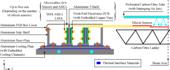
MVD: Due to the vacuum operation of the MVD, the power dissipated by the sensors (MIMOSIS, 75 mW/cm2, 120 W total) is transported conductively through Thermal Pyrolytic Graphite (TPG) sheets. It is guided into the peripherally located aluminium heat sinks which are actively cooled with 3MTM NovecTM 649 (see Fig. 1(a)). This minimises the material budget in the geometric acceptance and allows for a homogeneous temperature distribution across the sensors (10 K over the TPG), ensuring a high detection efficiency and low fake hit rate.
STS: The material budget requirement of the STS is maintained by holding the sensors on carbon fibre ladders and placing the electronics outside the geometric acceptance. The highly irradiated sensors around the beam-pipe ( 50 mW/cm2 at 10 ∘C) are cooled by impinging air-jets via perforated carbon-fibre tubes while natural air convection is deemed sufficient for the remaining less irradiated sensors. This is to avoid their thermal runaway by minimizing the rise of stable operating temperature caused at the end-of-life fluence and minimise the material budget. Furthermore, the electronics power dissipation of 40 kW is neutralised by custom-made aluminium heat sinks actively cooled with 3MTM NovecTM 649 to minimise the residual heat-transfer to the silicon sensors (see Fig. 1(b)). Both detector subsystems foresee to use a common 3MTM NovecTM 649 cooling plant with C nominal operating temperature.
(a)
(b)
Figure 1: Illustrations showing the thermal path of (a) MVD, and (b) STS. Drawings are not to scale.
3 Experimental Validation
Realistic demonstrators with pre-series detector components were built for both subsystems to validate the respective thermal management strategies, explore safety margins, and determine optimal operational parameters. The MVD demonstrator module, comprising an L-shaped heat sink and a TPG carrier in a vacuum chamber, represents the entire detector with its 16 thermally independent quadrants. Similarly, the STS demonstrator comprises one thermally active half-layer with dummy silicon sensor and electronics heating elements in realistic mechanical boundary conditions to accurately represent the interplay between the heating elements.
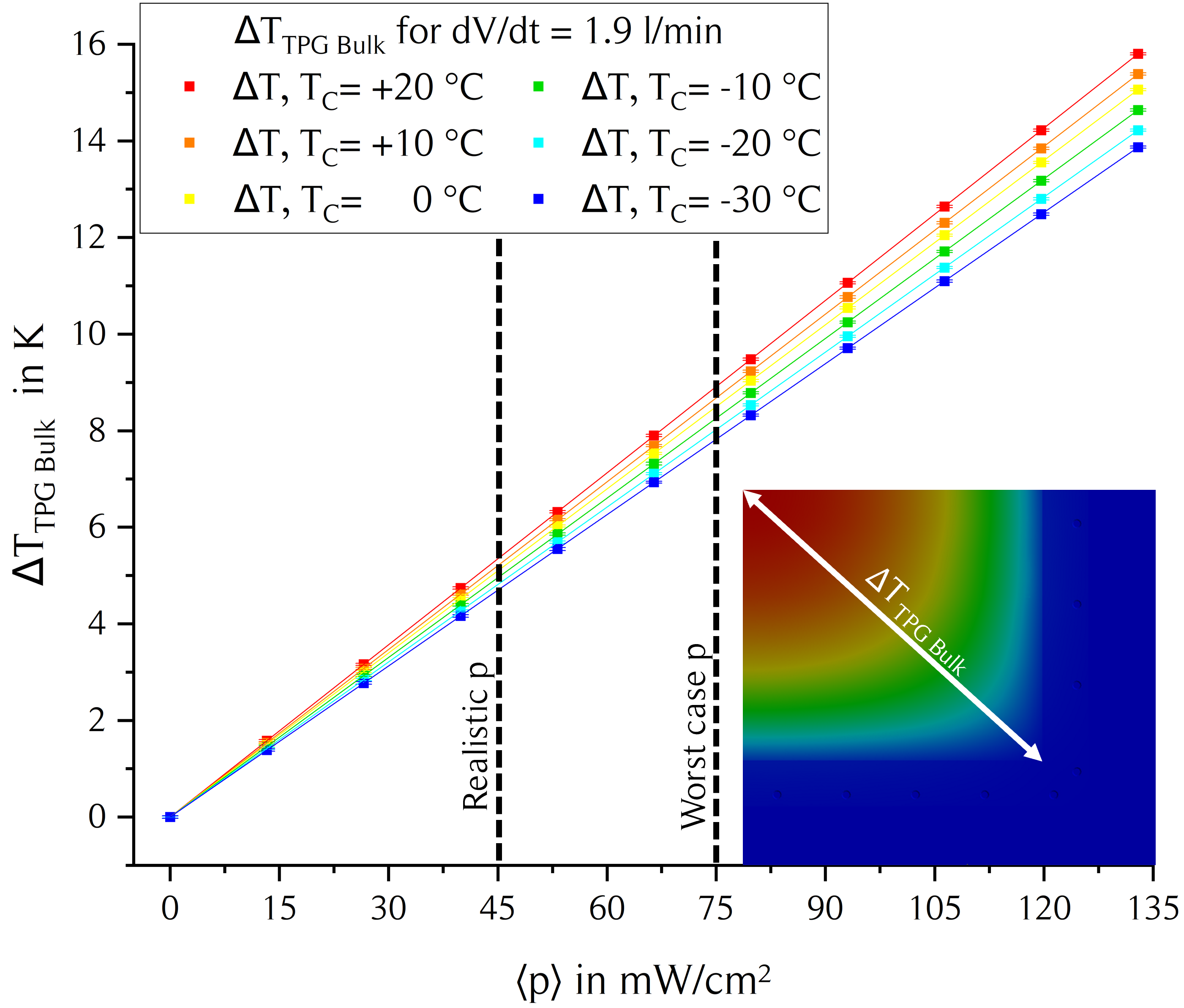
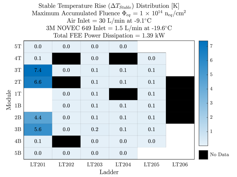
Fig. 2(a) shows the radiation-corrected maximum temperature gradient across the TPG bulk of a MVD quadrant () for varying sensor power and coolant temperatures. The data shows the 10 K at nominal operational conditions with large safety margins. The thermal runaway performance of the STS thermal demonstrator’s half-station at nominal operating conditions is shown in Fig. 2(b). The stable temperature rise () observed after mimicking sensor heating corresponding to end-of-lifetime fluence (EOL) distribution exhibits importance of the air sensor cooling both forced air convection via impinging air jets (central ladders; LT201-202; 7.4 K) and natural convection (peripheral ladders; LT203-206; 0 K), while ensuring sufficient neutralisation of FEE power dissipation.
(a)
(b)
Figure 2: (a) Measured maximum temperature gradient across the TPG carrier as a function of the sensor’s power dissipation and the coolant temperature. (b) Temperature rise of all half-station’s sensors before and after power dissipation mimicking the EOL fluence distribution.
4 Acknowledgements and Funding
FM and KA acknowledge the support from the BMBF Project-ID 05P21RFFC2 and 05P19VTFC1, respectively.
References
Ablyazimov et al. [2017]
T. Ablyazimov, et al. (CBM),
Challenges in QCD matter physics –The scientific programme of the Compressed Baryonic Matter experiment at FAIR,
Eur. Phys. J. A 53 (2017) 60. doi:10.1140/epja/i2017-12248-y. arXiv:1607.01487.
Agarwal [2023]
K. Agarwal (CBM),
The compressed baryonic matter (CBM) experiment at FAIR—physics, status and prospects,
Phys. Scripta 98 (2023) 034006. doi:10.1088/1402-4896/acbca7.
Stroth et al. [2022]
J. Stroth, et al., Technical Design Report for the CBM: Micro Vertex Detector (MVD), GSI, Darmstadt, 2022.
Heuser et al. [2013]
J. M. Heuser, et al., Technical Design Report for the CBM Silicon Tracking System (STS), GSI, Darmstadt, 2013.