Integrated Triply Resonant Electro-Optic Frequency Comb in Lithium Tantalate
Integrated frequency comb generators based on Kerr parametric oscillation [1] have led to chip-scale, gigahertz-spaced combs with new applications spanning hyperscale telecommunications, low-noise microwave synthesis, LiDAR and astrophysical spectrometer calibration [2, 3, 4, 5, 6]. Recent progress in lithium niobate (\chLiNbO3) photonic integrated circuits (PICs) has resulted in chip-scale electro-optic (EO) frequency combs [7, 8], offering precise comb-line positioning and simple operation without relying on the formation of dissipative Kerr solitons. However, current integrated EO combs face limited spectral coverage due to the large microwave power required to drive the non-resonant capacitive electrodes and the strong intrinsic birefringence of \chLiNbO3. Here, we overcome both challenges with an integrated triply resonant architecture, combining monolithic microwave integrated circuits (MMICs) with PICs based on the recently emerged thin-film lithium tantalate (\chLiTaO3) [9]. With resonantly enhanced EO interaction and reduced birefringence in \chLiTaO3, we achieve a four-fold comb span extension and a 16-fold power reduction compared to the conventional non-resonant microwave design. Driven by a hybrid-integrated laser diode, the comb spans over () with lines, and the generator fits within a compact footprint. We additionally observe that the strong EO coupling leads to an increased comb existence range approaching the full free spectral range of the optical microresonator. The ultra-broadband comb generator, combined with detuning-agnostic operation, could advance chip-scale spectrometry and ultra-low-noise millimeter wave synthesis [10, 11, 12, 13] and unlock octave-spanning EO combs. The methodology of co-designing microwave and optical resonators can be extended to a wide range of integrated electro-optics applications [14, 15, 16].
Microresonator optical frequency combs utilizing ultra-low loss and wafer-scale manufacturable photonic integrated circuits (PICs)—especially those based on foundry-available silicon nitride [17]—have been pivotal in advancing their fiber-based laboratory counterparts to chip-scale system-level applications in science and technology. Their versatility has been demonstrated in hyper-scale data communication [2], parallel LiDAR [6], neuromorphic computing [18], ultra-low-noise microwave synthesis [13, 12, 11], broadband spectroscopy [19], and astrophysical spectrometer calibration [4, 5].
The availability of thin-film lithium niobate (\chLiNbO3) using smart-cut [20] has triggered the development of electro-optic photonic integrated circuits with a large Pockels coefficient [21, 22]. This platform has re-ignited interest in electro-optic (EO) frequency combs [23, 24]. The recently emerged integrated EO combs [7, 8] complement soliton microcombs, exhibit similar compactness while offering innate stability of the repetition rates set by the microwave modulation frequency. Coherent sideband generation mediated by the EO Pockels effect does not have a minimum optical threshold, unlike parametric oscillations in Kerr comb formation. Additionally, it does not require the complex laser tuning mechanisms needed for dissipative Kerr soliton initiation [25, 26, 27, 28, 29]. Microcombs based on dissipative Kerr solitons also suffer from reduced conversion efficiency at lower repetition rates, particularly in the sub- frequencies (e.g., X-band for radar, K-band for 5G) [30].
Despite these advantages, EO combs still face outstanding challenges. The achieved frequency comb span, along with the line count, has been limited compared to soliton microcombs, which have attained octave spanning operation [31, 3] and the generation of more than 2000 comb lines [32, 33]. This is due to the insufficient EO coupling rate for generating thousands of sidebands [24, 7, 8]. As a result, large microwave pump power is needed to attain the requisite modulation depth. State-of-the-art integrated EO combs therefore require specialized power microwave circuits and bulk protective circulators [7, 8], which remain challenging to integrate into chip-scale systems. A further limitation stems from the intrinsic birefringence of \chLiNbO3 that imposes a span limit due to mode-mixing [8, 34]. Together, these factors have limited the bandwidth of state-of-the-art integrated EO comb below and exacerbated their microwave power requirements [7, 8]. Here, we overcome these challenges by bringing coplanar waveguide resonators from monolithic microwave integrated circuits (MMICs) into photonic integrated circuits and implementing an integrated triply resonant EO comb generator. The tight field confinement offered by microwave-photonic co-integration enhances the single-photon EO coupling rate by more than 300 times compared to bulk implementations [24]. Combined with dispersion-engineered lithium tantalate (\chLiTaO3) photonic integrated circuits that exhibit 17 times lower intrinsic birefringence than the workhorse EO material \chLiNbO3, and driven by a hybrid integrated semiconductor laser diode, the device is capable of generating over 2000 sidebands (a span) while consuming under of on-chip power. We attain an span with only of microwave power (), representing an over 16-fold power reduction compared to a conventional non-resonant electrode design. Moreover, the enhanced EO coupling rate in our triply resonant scheme is shown to lead to unprecedented detuning-agnostic operation with a comb existence range exceeding of the free spectral range (FSR) despite utilizing a microresonator, enabling full FSR sweeping of the comb lines free of spectral holes.
Results
Triply resonant cavity electro-optic architecture
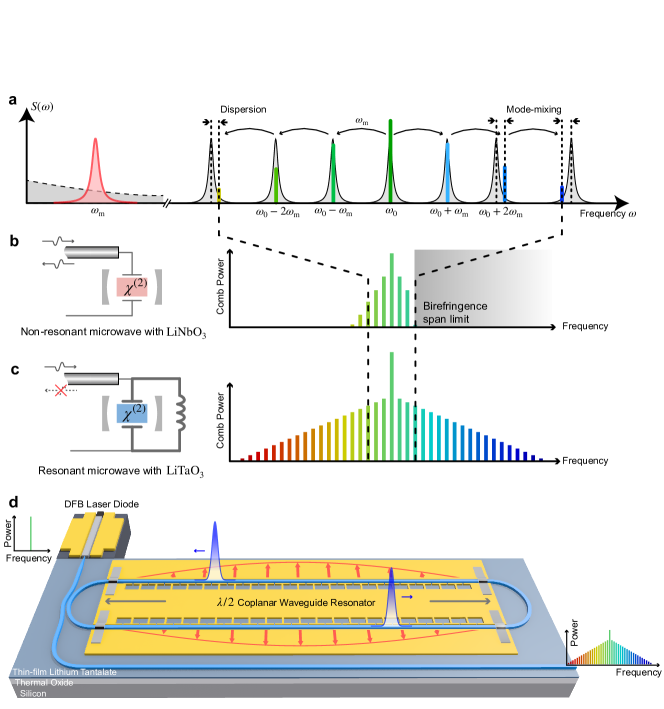
We leverage resonantly enhanced cascaded energy transfer, illustrated in Fig. 1a, for efficient EO comb generation, one of the earliest studied methods to generated optical frequency combs [23]. Figure 1b delineates the non-resonant lumped capacitive electrode design employed in state-of-the-art integrated EO combs based on \chLiNbO3 [7, 8]. As a result of the impedance mismatch with the input transmission line, a significant portion of the applied microwave power is reflected and dissipated as heat in the internal impedance of the microwave source. This inefficiency in power delivery necessitates the use of RF amplifiers to broaden the comb, which has, to date, limited state-of-the-art integrated EO combs to a span below [7, 8]. Impedance mismatch can be overcome by employing a microwave cavity (Fig. 1c), which increases EO comb generation efficiency [24]. However, this method has only been implemented with bulk optical and microwave cavities rather than in integrated EO combs. The present design, depicted in Fig. 1d, comprehensively tackles both challenges by integrating a monolithic microwave resonator with a \chLiTaO3 photonic racetrack resonator. Such triply resonant devices realized using bulk microwave cavities were originally considered for microwave photonic receivers [35, 36], and more recently, have been investigated for quantum coherent transduction between the microwave and the optical domains [37, 38, 39, 40, 41]. The deep sub-wavelength confinement of the microwave field of the co-planar waveguide resonator additionally leads to significantly enhanced EO coupling rates [38]. The advantage of this approach is seen by considering a three-wave mixing process between a pair of optical modes (, ) and a microwave mode () as in cavity electro-optics [42, 37], described by the Hamiltonian
| (1) |
where denotes the reduced Planck’s constant, and is the gross detuning with contributions from optical integrated dispersion and input laser detuning . Intimately related to the internal generator performance, the single-photon EO coupling rate due to nonlinearity is given by
| (2) |
The mode volumes and components of the spatial field distribution function (r) together define the vacuum electric field components . The components are associated with mode at frequency and permittivity , with and as the optical longitudinal mode index. Monolithic integration of the microwave and photonic subsystems enables reduced mode volumes and improved field overlap, allowing substantial increases in . The subsequently enhanced EO interaction internal to the device alleviates the constraint on on-chip microwave power. With a strong, undepleted microwave pump, the effective coupling rate between the optical modes is , where is the mean intracavity (microwave) photon number. This coupling rate is proportional to the comb span (Supplementary Information). Compared to non-resonant electrode designs, we reduce the required power by incorporating a CPW resonator, which enhances by the resonator finesse, reducing the external input microwave power required to generate a given comb span.
Birefringence span limit for electro-optic combs
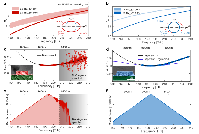
In addition to enhancing EO interaction, realizing broadband comb generation involves managing the optical dispersion such that across the broadest possible wavelength range. We first investigate the attainable dispersion in \chLiNbO3 and \chLiTaO3 racetrack resonators. In microresonators based on x-cut \chLiNbO3, transverse-electric (TE) modes experience a significant refractive index change from the ordinary () to extraordinary () values across the waveguide bends, whereas the transverse-magnetic (TM) modes experience mostly . As exemplified in Fig. 2a, the fundamental TE00 mode thus crosses and hybridizes with the TM00 mode, which introduces strong intra-modal coupling [43]. The gigahertz-level mode crossings result in uneven frequency spacings between longitudinal modes of the microresonator, interrupting the coherent spectral extension of the comb towards shorter wavelengths. For our thick waveguide design, we find that the \chLiNbO3 resonance spectrum is distorted above a critical frequency of (). The critical frequency decreases with increasing waveguide thickness [43], which limits the achievable flat dispersion span required for broadband comb generation in \chLiNbO3 racetrack resonators [8, 34]. As illustrated in Fig. 2b, by replacing \chLiNbO3 with \chLiTaO3, which has 17 times lower birefringence [9] (), we suppress the crossing of TE and TM modes. We compare the measured dispersion profiles of two identical racetrack resonators fabricated from \chLiNbO3 (Fig. 2c) and \chLiTaO3 (Fig. 2d). The results reveal significantly reduced local resonance frequency distortion due to birefringence mode mixing in \chLiTaO3. Furthermore, the dispersion-engineered \chLiTaO3 waveguide in Fig. 2d provides a flat global dispersion profile without measurable local birefringence distortion, making it suitable for octave-spanning EO comb generation. Figure 2e and 2f compare the simulated comb spectra for \chLiNbO3 and \chLiTaO3 with an effective coupling rate , using the non-dispersion-engineered profiles from the measurement depicted in Fig. 2c and 2d. We observe that the comb line power in \chLiNbO3 drops significantly beyond due to birefringence mode mixing, whereas the comb span in \chLiTaO3 is not limited by this issue.
Device implementation
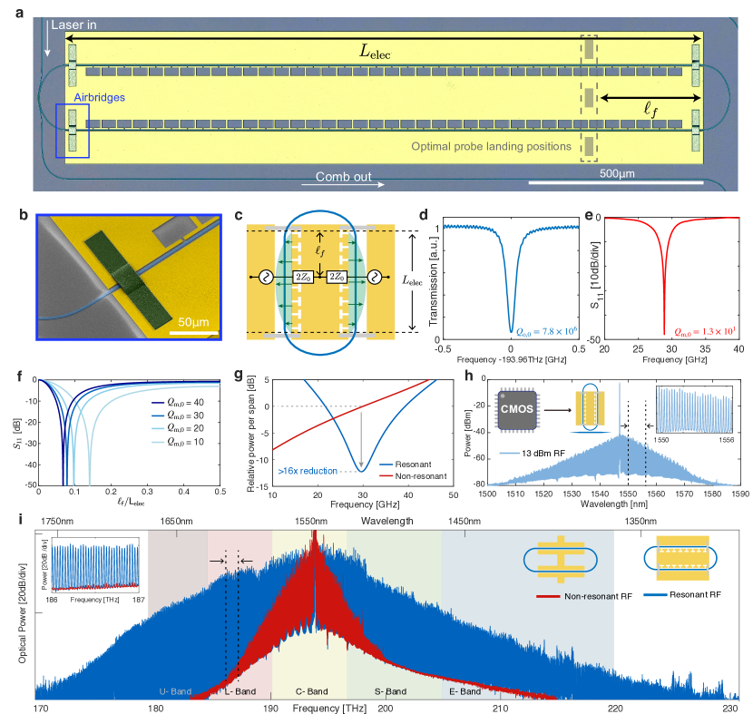
To realize the integrated triply resonant architecture, we employ an optical \chLiTaO3 racetrack resonator embedded in a gold coplanar-waveguide microwave resonator periodically loaded with an inductive slotted micro-structure, as illustrated in Fig. 3a. This loading increases the intrinsic microwave quality factor [44, 45] and simultaneously creates a slow-wave effect that aligns the resonance frequency with the optical FSR. Suspended metal bridges at both ends form short-circuit terminations (Fig. 3b), providing maximum electric field strength at the center (Fig. 3c). This field distribution achieves theoretical optimal phase matching between microwave and optical modes, maximizing (Supplementary Information). The microwave pump is coupled through a ground-signal-ground microwave probe positioned off-center for critical coupling. The high-confinement \chLiTaO3 photonic waveguides allow for gold electrodes to be placed away from their edges while maintaining high intrinsic optical quality factors (Fig. 3d). Figure 3e shows the measured reflection coefficient of the critically coupled microwave resonator, with a . This resonator topology allows for coupling rate tuning via adjustment of the probe landing position without affecting the field distribution. This technique guarantees a critically coupled microwave mode for a wide range of intrinsic quality factors, as illustrated in Fig. 3f. The optical comb sidebands and microwave pump are simultaneously resonant to increase the modulation efficiency.
In our triply resonant system, the single-photon coupling rate is measured to be (Supplementary Information). The microwave resonator is critically coupled to maximize the intracavity photon number and consequently the effective coupling rate . For a critically coupled standing-wave resonator, the intracavity power is enhanced by its finesse with respect to the incident power. A four-fold improvement in is expected compared to the modulation depth of a wide non-resonant electrode structure (Supplementary Information). The improvement is substantially higher than because the non-resonant electrodes do not behave as a system of unity finesse. Instead, waves are inefficiently coupled to the electrodes due to impedance mismatch with the probe, subsequently undergoing multiple reflections and partial destructive interference. The effect can be fully captured by a transmission line model (Supplementary Information). This also implies that the resonant structure requires 16 times less microwave power to achieve the same span, as shown in Fig. 3g. Figure 3h shows the triply resonant comb spectrum generated with of on-chip power on an under-coupled LTOI resonator. Figure 3i compares the EO comb spectrum generated in two similar over-coupled LTOI racetrack microresonators with non-resonant and resonant microwave structures, both featuring identical optical waveguide cross sections and waveguide-electrode gaps. In both cases, the devices are pumped with an on-chip microwave power of at a carrier frequency around . In the non-resonant design, we measure a comb span of at from the first-order sidebands, corresponding to an approximate comp slope of . A fourfold increase in the comb span (or 16 times lower power requirement for the same span) is observed as a result of the microwave resonator, with over measured span (Fig. 3e) at a slope of about . The slight asymmetry of the comb is due to the frequency-dependent optical coupling rate.
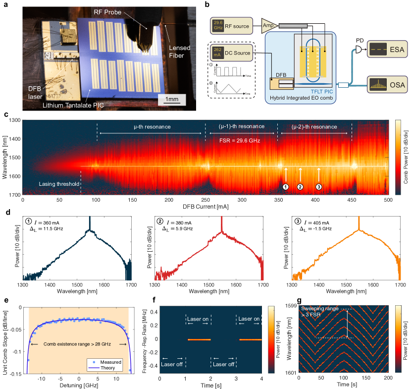
Next, we study the range of laser detuning over which EO combs can be sustained, in the presence of the MMIC cavity-enhanced microwave field. Figure 4a shows a photograph of the hybrid-integrated comb generator, and Fig. 4b depicts the experimental setup. We butt-couple a distributed feedback (DFB) laser diode to the edge of the LTOI chip with a coupling loss of at the facet. The laser diode is controlled by an external DC current source, and the generated comb is collected from the photonic chip with a lensed fiber. Figure 4c illustrates the variations in comb spectra for different laser currents, and three example spectra are presented in Fig. 4d. As the current increases, the pump laser frequency is swept across three FSRs. Notably, we obtain a broadband comb immediately after the current passes the lasing threshold, and the broad span can be maintained over a wide current range. The comb existence range is given by (Supplementary Information). Figure 4e depicts the measured comb slope at a offset () from the laser carrier () as a function of laser detuning. The comb slope remained nearly constant for over , which constitutes of the FSR. This observation indicates that for a randomly chosen pump frequency, a comb with a similar span can be generated with probability. Figure 4f illustrates the repetition rate signal measured during periodic laser switching, demonstrating stable turnkey operation. The large comb existence range enables continuous sweeping of all comb lines across the entire FSR, leaving no spectral hole within the span (Fig. 4g). This feature is particularly crucial for chip-based sensing [19] and coherent ranging applications [6].
Conclusion and outlook
In summary, we have demonstrated an ultra-broadband integrated triply resonant EO frequency comb generator using the newly emerged thin-film \chLiTaO3 platform [9]. The material choice helps overcome the birefringence span limit for spectral coverage faced by the conventionally used \chLiNbO3 [7, 8, 24]. We utilize a monolithic standing-wave microwave resonator to optimize for field overlap and phase matching with the optical modes, achieving a single-photon EO coupling rate , over 300 times larger than prior bulk resonant realization [24]. This critically coupled MMIC resonator additionally enhances the intracavity microwave pump photon number while eliminating the power reflection, and, by extension, the effective EO coupling rate. Strong coupling enables broadband comb generation over a laser detuning range exceeding FSR, facilitating turnkey operation with a free-running DFB laser diode and full FSR sweeping. This feature permits hybrid integration of the laser diode such that the comb generator fits within a footprint. Crucially, as a result of the efficient optical sideband generation, we attain a comb span greater than with over 2000 comb lines, far exceeding the telecommunications E-, S-, C-, L-, and U- bands at spacing. This ultra-broad comb is realized with gross on-chip power consumption below , including contributions from both the microwave pump and the laser diode current. Moreover, a low microwave pump power of gives rise to a comb span, representing a 16-fold power reduction compared to non-resonant electrodes. This advancement sets the stage for further system-level integration with low-power, analog CMOS-compatible microwave circuitry as well as efficient \chGaAs and \chGaN MMICs for hybrid microwave photonic processors and broadband sensors. Beyond comb generation, the triply resonant Hamiltonian given by Eq. 1 also permits effective interaction between the microwave and optical modes, mediated instead by an optical pump. Extending the present integrated architecture to superconducting circuits can thus facilitate quantum state transfer of millimeter-wave superconducting qubits with less stringent cooling requirements [46, 47]. By replacing the pulley-style optical coupler with a coupling resonator for frequency-selective coupling [8], we anticipate that self-referenced octave-spanning EO comb generation may be within reach. Such broadband EO combs have the potential to significantly enhance low-noise microwave generation through partial frequency division [11, 12, 13, 10]. Notably, the number of comb lines directly impacts the extent of phase noise suppression, potentially achieving more than 60 dB in our implementation. Our results therefore represent a significant step towards the field deployment of EO comb technology, establishing the monolithic microwave co-design strategy for high-performance integrated EO photonics.
Acknowledgments The samples were fabricated in the EPFL Center of MicroNanoTechnology (CMi) and the Institute of Physics (IPHYS) cleanroom. This work has received funding from Swiss National Science Foundation grant no. 211728 (Bridge Discovery). The LTOI wafers were fabricated in Shanghai Novel Si Integration Technology (NSIT) and the SIMIT-CAS.
Author contributions J.Z. and J.R. designed the photonic resonator. C.D. and G.S.B. designed the microwave resonator. C.W. and X.O. prepared the LTOI substrate. C.W. and J.Z. fabricated the devices. J.Z., G.L., G.S.B., J.H., C.W., W.K., T.B., and N.K. carried out the measurements. J.Z., J.R., G.S.B., G.L., C.D., W.K., T.B., and N.K. analyzed the data. J.Z., J.R., G.S.B., W.K., T.B., and T.J.K. wrote the manuscript with contributions from all authors. Z.L. and M.C. helped with the project. J.R., G.S.B., and T.J.K. supervised the project.
Competing interests The authors declare no competing financial interests.
Data Availability Statement The code and data used to produce the plots within this work will be released on the repository Zenodo upon publication of this preprint.
References
- Kippenberg et al. [2018] T. J. Kippenberg, A. L. Gaeta, M. Lipson, and M. L. Gorodetsky, Science 361, eaan8083 (2018).
- Marin-Palomo et al. [2017] P. Marin-Palomo, J. N. Kemal, M. Karpov, A. Kordts, J. Pfeifle, M. H. Pfeiffer, P. Trocha, S. Wolf, V. Brasch, M. H. Anderson, et al., Nature 546, 274 (2017).
- Spencer et al. [2018] D. T. Spencer, T. Drake, T. C. Briles, J. Stone, L. C. Sinclair, C. Fredrick, Q. Li, D. Westly, B. R. Ilic, A. Bluestone, et al., Nature 557, 81 (2018).
- Obrzud et al. [2019] E. Obrzud, M. Rainer, A. Harutyunyan, M. H. Anderson, J. Liu, M. Geiselmann, B. Chazelas, S. Kundermann, S. Lecomte, M. Cecconi, A. Ghedina, E. Molinari, F. Pepe, F. Wildi, F. Bouchy, T. J. Kippenberg, and T. Herr, Nature Photonics 13, 31 (2019).
- Suh et al. [2019] M.-G. Suh, X. Yi, Y.-H. Lai, S. Leifer, I. S. Grudinin, G. Vasisht, E. C. Martin, M. P. Fitzgerald, G. Doppmann, J. Wang, et al., Nature photonics 13, 25 (2019).
- Riemensberger et al. [2020] J. Riemensberger, A. Lukashchuk, M. Karpov, W. Weng, E. Lucas, J. Liu, and T. J. Kippenberg, Nature 581, 164 (2020).
- Zhang et al. [2019] M. Zhang, B. Buscaino, C. Wang, A. Shams-Ansari, C. Reimer, R. Zhu, J. M. Kahn, and M. Lončar, Nature 568, 373 (2019).
- Hu et al. [2022a] Y. Hu, M. Yu, B. Buscaino, N. Sinclair, D. Zhu, R. Cheng, A. Shams-Ansari, L. Shao, M. Zhang, J. M. Kahn, et al., Nature photonics 16, 679 (2022a).
- Wang et al. [2024] C. Wang, Z. Li, J. Riemensberger, G. Lihachev, M. Churaev, W. Kao, X. Ji, J. Zhang, T. Blesin, A. Davydova, Y. Chen, K. Huang, X. Wang, X. Ou, and T. J. Kippenberg, Nature 629, 784 (2024).
- Li et al. [2014] J. Li, X. Yi, H. Lee, S. A. Diddams, and K. J. Vahala, Science 345, 309 (2014).
- Sun et al. [2024] S. Sun, B. Wang, K. Liu, M. W. Harrington, F. Tabatabaei, R. Liu, J. Wang, S. Hanifi, J. S. Morgan, M. Jahanbozorgi, et al., Nature , 1 (2024).
- Kudelin et al. [2024] I. Kudelin, W. Groman, Q.-X. Ji, J. Guo, M. L. Kelleher, D. Lee, T. Nakamura, C. A. McLemore, P. Shirmohammadi, S. Hanifi, et al., Nature , 1 (2024).
- Zhao et al. [2024] Y. Zhao, J. K. Jang, G. J. Beals, K. J. McNulty, X. Ji, Y. Okawachi, M. Lipson, and A. L. Gaeta, Nature 627, 546 (2024).
- Yu et al. [2022] M. Yu, D. Barton III, R. Cheng, C. Reimer, P. Kharel, L. He, L. Shao, D. Zhu, Y. Hu, H. R. Grant, et al., Nature 612, 252 (2022).
- Hu et al. [2021] Y. Hu, M. Yu, D. Zhu, N. Sinclair, A. Shams-Ansari, L. Shao, J. Holzgrafe, E. Puma, M. Zhang, and M. Lončar, Nature 599, 587 (2021).
- Yu et al. [2023] M. Yu, R. Cheng, C. Reimer, L. He, K. Luke, E. Puma, L. Shao, A. Shams-Ansari, X. Ren, H. R. Grant, et al., Nature Photonics 17, 666 (2023).
- Kippenberg et al. [2011] T. J. Kippenberg, R. Holzwarth, and S. A. Diddams, science 332, 555 (2011).
- Feldmann et al. [2021] J. Feldmann, N. Youngblood, M. Karpov, H. Gehring, X. Li, M. Stappers, M. Le Gallo, X. Fu, A. Lukashchuk, A. S. Raja, et al., Nature 589, 52 (2021).
- Suh et al. [2016] M.-G. Suh, Q.-F. Yang, K. Y. Yang, X. Yi, and K. J. Vahala, Science 354, 600 (2016).
- Levy et al. [1998] M. Levy, R. Osgood Jr, R. Liu, L. Cross, G. Cargill Iii, A. Kumar, and H. Bakhru, Applied Physics Letters 73, 2293 (1998).
- Zhu et al. [2021] D. Zhu, L. Shao, M. Yu, R. Cheng, B. Desiatov, C. Xin, Y. Hu, J. Holzgrafe, S. Ghosh, A. Shams-Ansari, et al., Advances in Optics and Photonics 13, 242 (2021).
- Wang et al. [2018] C. Wang, M. Zhang, X. Chen, M. Bertrand, A. Shams-Ansari, S. Chandrasekhar, P. Winzer, and M. Lončar, Nature 562, 101 (2018).
- Kourogi et al. [1993] M. Kourogi, K. Nakagawa, and M. Ohtsu, IEEE Journal of Quantum Electronics 29, 2693 (1993).
- Rueda et al. [2019] A. Rueda, F. Sedlmeir, M. Kumari, G. Leuchs, and H. G. Schwefel, Nature 568, 378 (2019).
- Herr et al. [2014] T. Herr, V. Brasch, J. D. Jost, C. Y. Wang, N. M. Kondratiev, M. L. Gorodetsky, and T. J. Kippenberg, Nature Photonics 8, 145 (2014).
- Yi et al. [2016] X. Yi, Q.-F. Yang, K. Y. Yang, and K. Vahala, Optics Letters 41, 2037 (2016).
- Lucas et al. [2017] E. Lucas, H. Guo, J. D. Jost, M. Karpov, and T. J. Kippenberg, Physical Review A 95, 043822 (2017).
- Guo et al. [2017] H. Guo, M. Karpov, E. Lucas, A. Kordts, M. H. P. Pfeiffer, V. Brasch, G. Lihachev, V. E. Lobanov, M. L. Gorodetsky, and T. J. Kippenberg, Nature Physics 13, 94 (2017).
- Stone et al. [2018] J. R. Stone, T. C. Briles, T. E. Drake, D. T. Spencer, D. R. Carlson, S. A. Diddams, and S. B. Papp, Physical Review Letters 121, 063902 (2018).
- Liu et al. [2020] J. Liu, E. Lucas, A. S. Raja, J. He, J. Riemensberger, R. N. Wang, M. Karpov, H. Guo, R. Bouchand, and T. J. Kippenberg, Nature Photonics 14, 486 (2020).
- Pfeiffer et al. [2017] M. H. Pfeiffer, C. Herkommer, J. Liu, H. Guo, M. Karpov, E. Lucas, M. Zervas, and T. J. Kippenberg, Optica 4, 684 (2017).
- Anderson et al. [2021] M. H. Anderson, R. Bouchand, J. Liu, W. Weng, E. Obrzud, T. Herr, and T. J. Kippenberg, Optica 8, 771 (2021).
- Cheng et al. [2024] R. Cheng, M. Yu, A. Shams-Ansari, Y. Hu, C. Reimer, M. Zhang, and M. Lončar, Nature Communications 15, 3921 (2024).
- Hu et al. [2022b] Y. Hu, M. Yu, N. Sinclair, D. Zhu, R. Cheng, C. Wang, and M. Lončar, Nature Communications 13, 6293 (2022b).
- Ilchenko et al. [2002] V. Ilchenko, A. Savchenkov, A. Matsko, and L. Maleki, IEEE Photonics Technology Letters 14, 1602 (2002).
- Ilchenko et al. [2003] V. S. Ilchenko, A. A. Savchenkov, A. B. Matsko, and L. Maleki, J. Opt. Soc. Am. B, JOSAB 20, 333 (2003).
- Rueda et al. [2016] A. Rueda, F. Sedlmeir, M. C. Collodo, U. Vogl, B. Stiller, G. Schunk, D. V. Strekalov, C. Marquardt, J. M. Fink, O. Painter, G. Leuchs, and H. G. L. Schwefel, Optica 3, 597 (2016).
- Javerzac-Galy et al. [2016] C. Javerzac-Galy, K. Plekhanov, N. R. Bernier, L. D. Toth, A. K. Feofanov, and T. J. Kippenberg, Physical Review A 94, 053815 (2016).
- Fan et al. [2018] L. Fan, C.-L. Zou, R. Cheng, X. Guo, X. Han, Z. Gong, S. Wang, and H. X. Tang, Science Advances 4, eaar4994 (2018).
- Holzgrafe et al. [2020] J. Holzgrafe, N. Sinclair, D. Zhu, A. Shams-Ansari, M. Colangelo, Y. Hu, M. Zhang, K. K. Berggren, and M. Lončar, Optica 7, 1714 (2020).
- McKenna et al. [2020] T. P. McKenna, J. D. Witmer, R. N. Patel, W. Jiang, R. Van Laer, P. Arrangoiz-Arriola, E. A. Wollack, J. F. Herrmann, and A. H. Safavi-Naeini, Optica 7, 1737 (2020).
- Tsang [2010] M. Tsang, Physical Review A 81, 063837 (2010).
- Pan et al. [2019] A. Pan, C. Hu, C. Zeng, and J. Xia, Optics express 27, 35659 (2019).
- Shin et al. [2010] J. Shin, S. R. Sakamoto, and N. Dagli, Journal of lightwave technology 29, 48 (2010).
- Kharel et al. [2021] P. Kharel, C. Reimer, K. Luke, L. He, and M. Zhang, Optica 8, 357 (2021).
- Sahu et al. [2022] R. Sahu, W. Hease, A. Rueda, G. Arnold, L. Qiu, and J. M. Fink, Nature Communications 13, 1276 (2022).
- Sahu et al. [2023] R. Sahu, L. Qiu, W. Hease, G. Arnold, Y. Minoguchi, P. Rabl, and J. M. Fink, Science 380, 718 (2023).