Efficient UAV Hovering, Resource Allocation, and Trajectory Design for ISAC with Limited Backhaul Capacity
Abstract
In this paper, we investigate the joint resource allocation and trajectory design for a multi-user, multi-target unmanned aerial vehicle (UAV)-enabled integrated sensing and communication (ISAC) system, where the link capacity between a ground base station (BS) and the UAV is limited. The UAV conducts target sensing and information transmission in orthogonal time slots to prevent interference. As is common in practical systems, sensing is performed while the UAV hovers, allowing the UAV to acquire high-quality sensing data. Subsequently, the acquired sensing data is offloaded to the ground BS for further processing. We jointly optimize the UAV trajectory, UAV velocity, beamforming for the communication users, power allocated to the sensing beam, and time of hovering for sensing to minimize the power consumption of the UAV while ensuring the communication quality of service (QoS) and successful sensing. Due to the prohibitively high complexity of the resulting non-convex mixed integer non-linear program (MINLP), we employ a series of transformations and optimization techniques, including semidefinite relaxation, big-M method, penalty approach, and successive convex approximation, to obtain a low-complexity suboptimal solution. Our simulation results reveal that 1) the proposed design achieves significant power savings compared to two baseline schemes; 2) stricter sensing requirements lead to longer sensing times, highlighting the challenge of efficiently managing both sensing accuracy and sensing time; 3) the optimized trajectory design ensures precise hovering directly above the targets during sensing, enhancing sensing quality and enabling the application of energy-focused beams; and 4) the proposed trajectory design balances the capacity of the backhaul link and the downlink rate of the communication users.
Index Terms:
Resource allocation, trajectory design, UAV, ISAC, hovering, radar pulse sensing, backhaul link, MINLP.I Introduction
With the rapid development of new services for future wireless networks, the sixth generation (6G) of wireless communication systems is expected to become a fully intelligent network enabling a multitude of environment-and location-aware applications such as autonomous driving, remote healthcare, and smart industry. To support these applications, a seamless 6G wireless network is needed, providing both high-precision sensing capabilities and wireless information transmission. To this end, integrated sensing and communication (ISAC) has recently drawn significant attention from academia and industry. ISAC is capable of increasing spectrum efficiency and facilitating the sharing of the physical infrastructure for sensing and communications [2]. Motivated by these advantages, the authors in [3, 4] considered ISAC networks with a specific focus on terrestrial systems. However, terrestrial ISAC systems, despite their potential, are often hindered by obstacles on the ground that may obstruct the line of sight (LoS) to sensing targets.
Compared to conventional cellular systems which are based on a fixed terrestrial infrastructure, unmanned aerial vehicle (UAV)-enabled communication systems can support on-demand connectivity by flexibly deploying UAV-enabled wireless transceivers in a target area. For example, in the case of natural disasters and major accidents, UAVs can be utilized as aerial base stations to establish temporary communication links in a timely and cost-effective manner. Moreover, UAV-aided wireless communication, capitalizing on the flexible deployment[5, 6], can exploit LoS links. These LoS connections cannot only enhance communication performance but also serve as a critical element for accurate target sensing. This is because target detection and parameter estimation usually require LoS links between the sensing transceivers and the sensing targets. Furthermore, due to their high maneuverability, UAVs can quickly approach a desired target, which can significantly reduce the transmit power required for sensing[7, 8]. Despite these promising features, only few works in the existing literature have studied UAV-enabled ISAC [9, 10, 11, 12, 13]. The authors in [9] optimized the trajectory, transmit beamforming, and radar signals of a UAV-enabled ISAC system to improve the communication data rate while ensuring a required sensing beam pattern gain. In [10, 11], a periodic sensing and communication scheme for UAV-enabled ISAC systems was introduced and the achievable rate was maximized by jointly optimizing the UAV’s trajectory, transmit precoder, and sensing start time subject to sensing frequency and beam pattern gain constraints. The authors in [12] proposed a novel integrated sensing, jamming, and communication framework for UAV-enabled downlink communications to maximize the number of securely served users while considering a tracking performance constraint. In [13], the authors considered single-antenna UAV-enabled integrated sensing, computing, and communication, where the UAV sensed a target and offloaded computational tasks to the ground base station (BS). The works in [9, 10, 11, 12, 13] did not take into account UAV aerodynamic power consumption and velocity optimization, crucial for coping with the limited battery life of UAVs. Efficient and prolonged UAV operation requires addressing these aspects via resource allocation and trajectory design, enhancing overall performance and mission time. Furthermore, the authors of [9, 10, 11, 12, 13] primarily concentrated on optimizing the beam pattern gain for target sensing, while ignoring the potential impact of the sidelobes of the beam pattern. In fact, the presence of sidelobes can result in energy wastage and high interference, which may have adverse effects on the overall performance of the ISAC system[4, 3]. Moreover, these studies did not consider the signal-to-noise ratio (SNR) of the received radar echoes as a performance metric for sensing, which is a crucial aspect in practical ISAC systems. The reliable detection of radar echoes is essential for ensuring the successful completion of sensing tasks in practice. Therefore, in this paper, we consider the SNR of the received radar echoes as a performance metric for sensing. Besides, the ISAC systems considered in [9, 10, 11, 12, 13] may experience significant self-interference (SI) as the radar echoes maybe received before the information transmission is completed. While conventional full-duplex communication systems use SI cancellation techniques to mitigate interference, such methods may not be sufficient to suppress the SI below the level required for sensing due to the low received echo powers. This is primarily due to the high attenuation of the echo signal caused by the round-trip path-loss, which makes it challenging to achieve sufficient SI suppression. To address this issue, we propose to perform sensing and communication in orthogonal time slots, coupled with the adoption of pulse radar technology, which enables flexible adjustment of the sensing range. Besides, in [9, 10, 11, 12, 13], sensing was performed while the UAV was moving, which can potentially degrade sensing accuracy. In contrast, practical UAV-based sensing systems typically perform sensing while the UAV is hovering[14]. Therefore, in this paper, we incorporate this feature into our problem formulation to leverage the following advantages. First, when the UAV hovers above the target, a predetermined fixed beam pattern can be used for sensing, i.e., eliminating the need for continuous adjustment of the beam pattern based on the UAV’s flight path, which significantly reduces design complexity. Second, hovering during sensing circumvents the UAV-induced Doppler shift, simplifying sensing data signal processing. Furthermore, in [9, 10, 11, 12], it was assumed that the processing of the received sensing signals is done locally at the UAV, which can be challenging due to the UAV’s limited computational capabilities and battery resources. In fact, signal processing and analysis of sensing data require significant computing resources and energy, which creates a bottleneck for UAV-enabled sensing. To address this challenge, we propose to forward the received sensing echo signals to a ground BS via backhaul links for processing. Offloading the sensing data alleviates the computational burden on the UAV, enabling higher accuracy and lower latency in obtaining sensing results at the BS. Existing studies overlooked critical components such as aerodynamic power consumption, velocity optimization, the accumulated received echo SNR as performance metric for sensing, synthesizing a focused beam, optimal hovering during sensing, and the impact of the backhaul link capacity on system performance. This paper addresses these challenges and introduces a novel design framework to minimize the average UAV power consumption while meeting the QoS requirements of both the communication users and sensing tasks. The main contributions of this paper can be summarized as follows:
-
•
We consider a multi-user multi-target UAV-enabled ISAC system where the link capacity between the ground BS and the UAV is limited. We aim to minimize the average power consumption of the UAV, which involves optimizing not only the resource allocation and UAV trajectory but also the time when the UAV hovers for sensing, resulting in a non-convex mixed integer non-linear program (MINLP).
-
•
We introduce an innovative design strategy for the UAV’s radar beam, comprising the offline pre-design of its shape and online power allocation for sensing. This approach significantly reduces computational complexity, as the system focuses exclusively on optimizing the scaling factor during the online phase. Particularly, for sensing, our emphasis is on synthesizing a concentrated beam with minimal sidelobes in the offline phase and guaranteeing a required accumulated SNR, facilitated by precise UAV hovering directly above the target, during sensing.
-
•
We develop an alternating optimization (AO) based resource allocation algorithm to solve the formulated non-convex MINLP optimization problem. In particular, we obtain a low-complexity sub-optimal solution by exploiting semi-definite relaxation, big-M method, and successive convex approximation (SCA). Moreover, we utilize the penalty approach for penalizing the objective function to ensure the equality constraint introduced by the required hovering of the UAV precisely above the target during sensing and for recovering the binary sensing indicator variables, enhancing the efficiency of the solution.
-
•
Our simulation results highlight the benefits of positioning the BS in close proximity to the sensing targets, facilitating efficient data offloading and accurate sensing. Additionally, our results affirm the effectiveness of the proposed algorithm in ensuring precise hovering directly above the targets during sensing, benefiting accurate and reliable target detection.
Notations: In this paper, matrices and vectors are denoted by boldface capital letters and lowercase letters , respectively. and denote the spaces of real-valued and complex-valued matrices, respectively. , , , and are the transpose, Hermitian, rank, and trace of matrix , respectively. indicates a positive semidefinite matrix. is the -by- identity matrix. and denote the absolute value of a complex scalar and the -norm of a vector, respectively. denotes statistical expectation. and stand for “distributed as” and “defined as”, respectively. The distribution of a circularly symmetric complex Gaussian random variable with mean and variance is denoted by . The gradient vector of function with respect to is denoted by .
II System Model
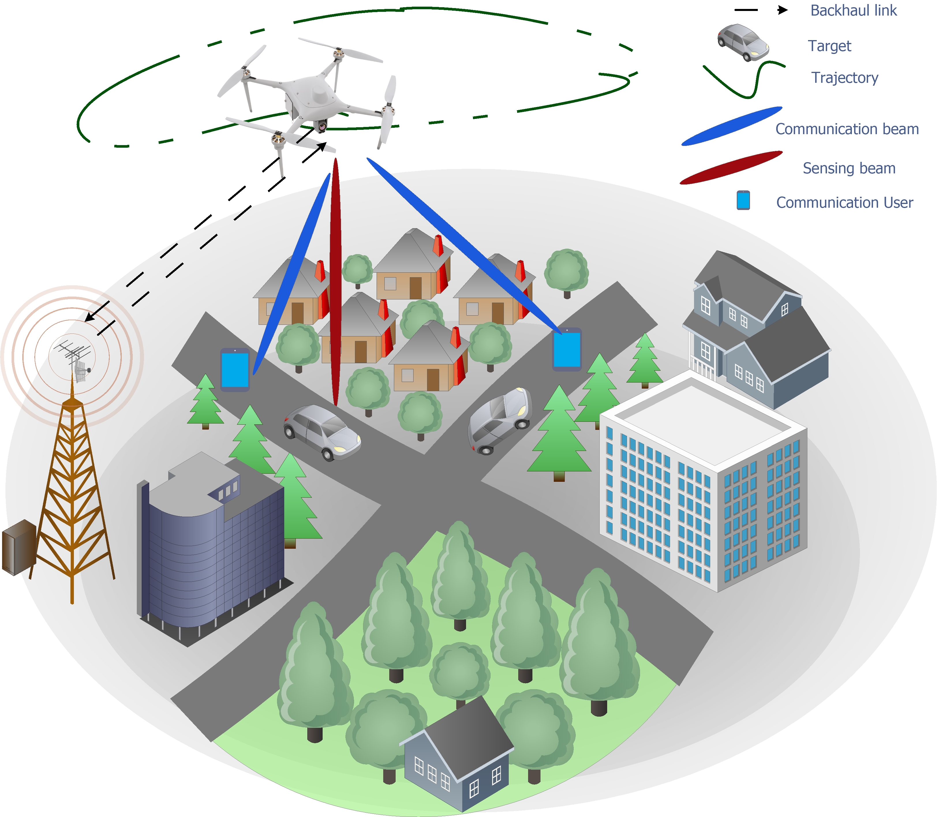
In this paper, we consider a rotary-wing UAV-assisted ISAC system, which provides downlink communication services for communication users and senses potential targets, as depicted in Fig. 1. To cater to the limited computational capabilities of the UAV, ensure low latency data processing, and enable real-time mission monitoring, the UAV offloads the sensing data to a ground BS for further processing [15]. The operation of the system follows a two-step process. The communication data is transmitted from the BS to the UAV, and subsequently, the UAV relays this data to the users. In certain time slots, the UAV switches to the sensing mode, receiving echo signals reflected by the sensing target. These echo signals are first compressed locally at the UAV, reducing the amount of data that needs to be offloaded to the BS. The compressed radar data are then transmitted to the ground BS. Finally, the BS performs central processing for target recognition based on the received compressed sensing data.
The UAV’s total flying time is divided into time slots of duration . Each time slot is assumed to be sufficiently small, such that the location of the UAV is approximately constant during a time slot to facilitate efficient trajectory and beamforming design for ISAC. In the subsequent subsections, we present the proposed ISAC framework in detail. We start by explaining the proposed frame structure. Then, we describe the signal model, including its radar and communication components, before modeling the backhaul links. Finally, we address the power consumption of the UAV, including the power required for local processing, offloading, and flying.
II-A ISAC Frame Structure for UAV
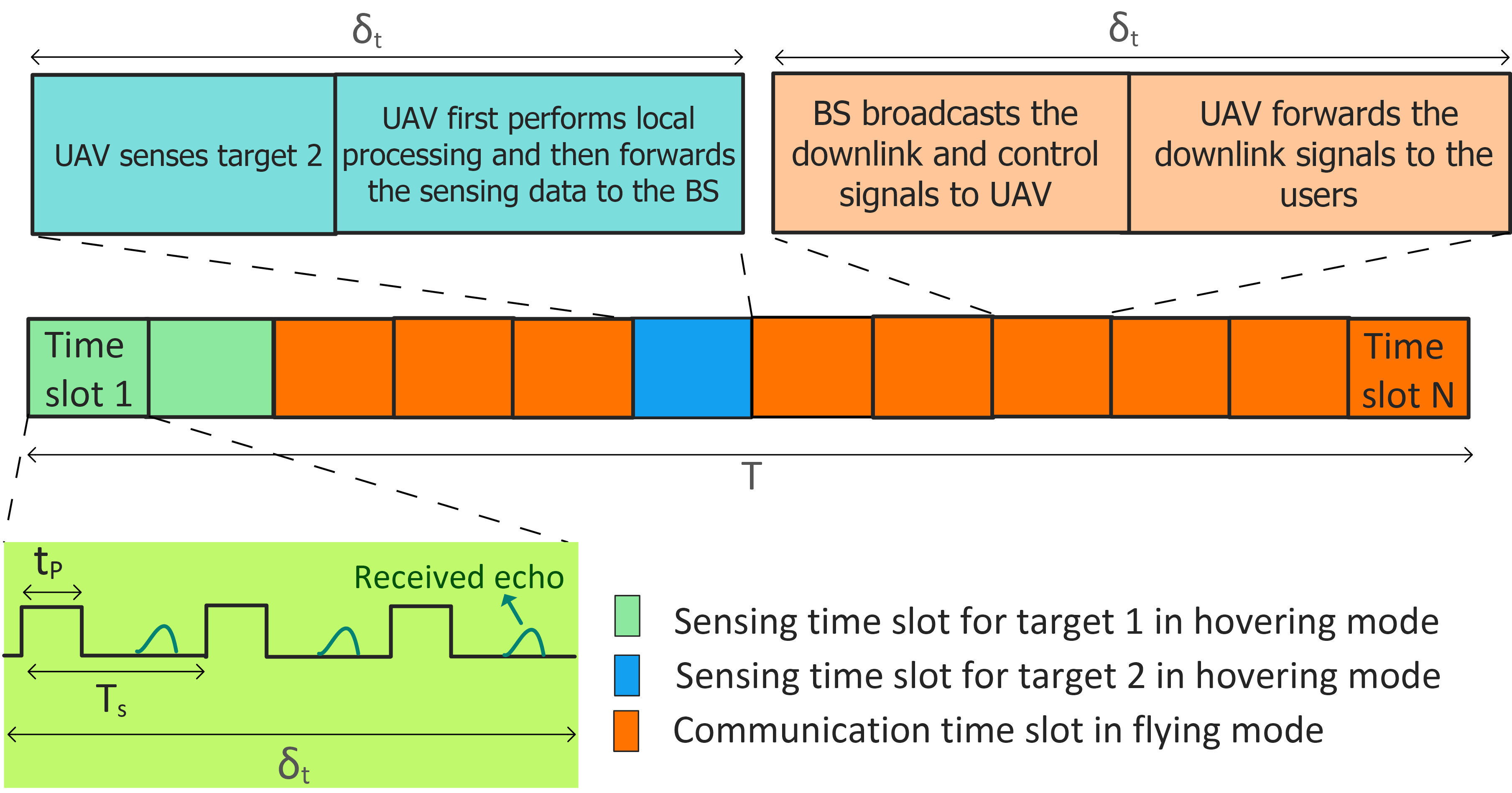
In the proposed UAV-ISAC frame structure, separate and dedicated time slots are employed for sensing and communication, as shown in Fig. 2. This strategy minimizes interference, ensuring the UAV’s efficient execution of both operations without compromising quality. The UAV communicates with the communication users in non-sensing slots while it senses the target in the sensing slots. However, the UAV can use only a maximum of time slots to limit the sensing duration for task effectiveness. During sensing, one target is sensed at a time to maximize sensing performance by focusing the beam pattern on the target. However, in what time slot sensing is performed is part of the optimization. To this end, we introduce the sensing indicator for target , . If , target is sensed in the -th time slot; otherwise, . Here, we force the UAV to hover above the sensing target. This choice offers several advantages. First, with the UAV hovering above the target, a fixed beam pattern can be designed, eliminating the need for continuous adjustment based on the UAV’s flight path, which simplifies the design process. Second, hovering during sensing helps mitigate UAV-induced Doppler shifts, simplifying the signal processing for sensing data. Third, it minimizes the impact of interference and multi-path effects, resulting in higher sensing performance which allows the UAV to focus the beam pattern with maximum accuracy on the target, enabling the system to extract vital information with optimal efficiency. The assumption of UAV hovering above the target during sensing is justified by its applicability in various real-world scenarios, including vital sign detection through radar technology, where precise UAV positioning is crucial for reliable measurements. These benefits make hovering during sensing preferable in practical UAV-based radar systems[14]. After sensing, the sensing data is offloaded to the ground BS via a backhaul link to leverage the ground BS’s computational capabilities. This offloading reduces latency and enhances sensing precision.
.
II-B Radar Signal
The UAV is equipped with a uniform linear array (ULA) with antennas for communication and sensing. We adopt a three-dimensional (3D) Cartesian coordinate system where the horizontal location of the UAV in time slot and the location of the potential target on the ground are denoted by and , respectively. The value of , , is predetermined based on the specific sensing tasks111The value of could be set based on an estimated location for target tracking or it could be a fixed location in the region of interest for target detection [10, 11].. While having initial knowledge of the target’s location is valuable, the complete sensing data acquisition involves a two-step process. Initially, the UAV acquires rough information to initiate the sensing process. Subsequently, it performs detailed sensing to gather sufficient data on the target which is then offloaded to the BS for further processing. In the considered system, the UAV’s initial knowledge guides the sensing process, ensuring efficient and accurate data acquisition. The offloading to the BS facilitates in-depth analysis and contributes to a comprehensive understanding of the target including the target’s location, angle, shape, velocity, size, and parameters. Moreover, it is assumed that the UAV flies in the plane at fixed altitude . While hovering over a given target, the UAV emits a narrow beam toward the direction of the target to extract information from the target. The radar signal with covariance matrix is transmitted towards the given target in a sensing slot. The transmit beam pattern gain from the UAV in the direction of target is given by
| (1) |
where
| (2) |
is the steering vector of the ULA equipped at the UAV, is the angle of departure corresponding to target , is the carrier wavelength, and denotes the spacing between two adjacent UAV antennas.
We adopt a two-phase strategy to optimize the design of the beam pattern and to maximize the quality of sensing.
II-B1 Shape of the Sensing Beam
In the offline phase, a highly directional sensing beam pattern is designed, efficiently catering to specific constraints required for optimal sensing. To facilitate high-quality sensing during the UAV’s hovering phase, the desired sensing location has to be illuminated by an energy-focused beam with low side lobe leakage, facilitating the separation of the desired echoes and clutter. The UAV employs a pre-designed highly directional sensing beam pattern characterized by a specific covariance matrix that defines the desired waveform. To this end, we discretize the angular domain into directions and generate the ideal beam pattern , where denotes the beam pattern power in direction , which is given by
where is the beamwidth used to sense one target [16], and is the angle of departure corresponding to target . In the hovering state, the horizontal distance between the UAV and the target is zero, resulting in an angle of zero degrees between the UAV and the target, i.e., . Consequently, to shape the beam, we adopt the minimum square error (MSE) criterion, which is given by [16]
| (3) | ||||
| s.t. | ||||
where is a scaling factor. Problem (3) is a semi-definite quadratic programming problem and can be efficiently solved in polynomial time by CVX.
II-B2 Scaling Power of the Sensing Beam
In the online phase, we scale and configure the beam pattern in real time. The employed radar beam pattern, denoted as , is obtained from (3), and remains fixed and does not depend on time slot . As mentioned before, the beam pattern is specifically designed for scenarios when the UAV hovers directly above the target. We introduce scaling factor , which is applied to the desired radar beam pattern matrix yielding for the covariance matrix used for sensing. This scaling factor allows for dynamic adjustment of the beam power during sensing.
We adopt pulse radar for sensing to ensure reliable echo detection at the transmitter and to provide flexibility in adjusting the sensing range. According to pulse radar theory, the sensing range is contingent upon the duration of the sensing pulse and the time taken to listen for the received echo [17]. Consequently, the system designer meticulously divides the available sensing time into two components to ensure dependable echo detection at the transmitter. As a result, each sensing slot comprises multiple scan rounds, within each of which the UAV transmits a scanning pulse lasting for a duration of , as shown in Fig 2. Following this transmission, the UAV switches to the listening mode to receive the target’s echo corresponding to the transmitted pulse. Consequently, each sensing round operates at a specific pulse repetition frequency (PRF). In particular, represents the duration of each sensing round, where corresponds to the duration of the listening mode (reception duration of the received radar echo). The number of sensing rounds is then given by . The echo signal received at the UAV in time slot is given by
| (4) |
where is the received additive white Gaussian noise (AWGN) at the UAV and is the round-trip channel matrix, which is given by
| (5) |
where denotes the channel power gain at the reference distance of m and . Moreover, denotes the reflection coefficient of target in time slot , and is the radar cross-section of target [17]. After receive beamforming with vector , the received echo signal at the UAV can be rewritten as
| (6) |
As a result, the radar output SNR for target detection at the UAV is given by
| (7) |
Exploiting maximum ratio combining, i.e., , we obtain
| (8) |
To achieve satisfactory sensing performance, we require the accumulated sensing SNR of target to be higher than a pre-defined minimum threshold as follows
| (9) |
where is the minimum SNR required at the UAV for sensing target . This condition is contingent on the target remaining stationary and not in motion during sensing.
II-C Communication Signal
The horizontal location of the communication users is denoted by . Consequently, the channel vector between the UAV and user is denoted by , and given by
| (10) |
based on the free space channel model. In the non-sensing slots, the UAV transmits simultaneously information symbols , , , to the communication users. Then, the received signal at user can be written as
| (11) |
where denotes the transmit beamforming vector and is the AWGN at user . As a result, the received SINR at user in time slot is given by
| (12) |
II-D Backhaul Model
II-D1 Radar pulse
Based on the PRF, the minimum and maximum sensing ranges, for which the UAV can detect a target, are given by[17]
| (13) |
II-D2 UAV-BS
In each sensing slot, the UAV has to first sample and quantize the received echo signal based on the desired sensing resolution, and then forward the quantized data to the BS. Consequently, we model the backhaul capacity required for conveying the sampled and quantized echoes from the UAV to the BS during the listening time, , as follows [18]
| (14) |
where is the number of bits needed to characterize a quantized value of the echo signal, is the resolution of the radar in meters determined by the pulse width, type of target, and efficiency of the radar[17], and is the bandwidth of the backhaul link. After compression of the radar data at the UAV, the compressed data are offloaded to the BS for further processing and analysis. We model the achievable data rate between the UAV and the BS based on an equivalent single-input single-output (SISO) link as follows222Since the channel between the UAV and the BS is LoS, only one spatial degree of freedom is available. Accordingly, the backhaul channel matrix is rank-one with a unique non-zero singular value.
| (15) |
where , and is the antenna gain for the backhaul link. Also, , where is the height of the BS. is the transmission power needed for offloading the radar data from the UAV to the BS and is the variance of the noise at the BS. To guarantee successful real-time communication between the UAV and the BS, the production rate (the rate at which sampled and quantized echoes are conveyed from the UAV to the BS) should be smaller than the achievable rate of the backhaul link. Thus, the following inequality must hold in the sensing slots
| (16) |
where , , denotes the data compression factor resulting from the local compression carried out by the UAV.
II-D3 BS-UAV
Besides, the backhaul constraint required for offloading of sensing data, the link between the BS to the UAV must also satisfy a minimum QoS requirement to ensure successful data transmission to the users
| (17) |
where is a minimum QoS requirement for communication user , and is the AWGN variance at the UAV.
II-E Power Consumption Model
Besides, the power consumption incurred for data transmission and sensing, the UAV also consumes power for offloading, local data processing, and flying.
II-E1 Offloading Power Consumption of the UAV
In the context of our system, offloading is a critical strategy to manage the significant amount of radar data generated during the sensing phase. The UAV needs to efficiently transmit this data to the BS with transmit power for further processing.
II-E2 Local Power Consumption of the UAV
We model the power consumption required for local data processing, i.e., for data compression at the UAV, as follows [19]
| (18) |
where is a constant related to the hardware architecture of the UAV and (cycles/sec) is the local computation resource of the UAV.
II-E3 Aerodynamic Power Consumption of the UAV
The propulsion power consumption depends on the flying mode of the UAV [6, 20]. In particular, the aerodynamic power consumption for rotary-wing UAVs is a function of the flight velocity [20]. The total power consumption in time slot can be written as
| (19) |
where and = The parameters of the power consumption model are defined in Table I[20].
| Notations | Definitions |
|---|---|
| Blade angular velocity in radians/second | |
| Rotor radius in meter | |
| Air density in | |
| Rotor solidity in | |
| Rotor disc area in | |
| Blade profile power during hovering in Watt | |
| Induced power during hovering in Watt | |
| Mean rotor induced velocity in forward flight in m/s | |
| Fuselage drag ratio | |
| W | Circuit power consumption of RF chain |
III Problem Formulation
In this paper, we aim to minimize the average power consumption of the UAV which includes the transmission power, aerodynamic power consumption, and power consumption for offloading by jointly optimizing the beamforming for communication, the power for sensing (), the UAV’s trajectory (), the velocity (), and the sensing indicator while guaranteeing the QoS of the communication users as well as the sensing targets. As a result, the optimization problem is mathematically formulated as follows:
| s.t. | ||||
| (20) | ||||
where and denote the power amplifier efficiency and the circuit power consumption of the radio frequency (RF) chain of one antenna element, respectively. In optimization problem , is the set of optimization variables. C1 limits the transmit power of the UAV, where is the maximum transmit power. C2 guarantees that the average achievable data rate of the communication users in non-sensing slots does not fall below . C3 ensures that the accumulated sensing SNR at the UAV exceeds a specified minimum threshold, denoted by , necessary for effective target sensing. C4 indicates that the rate of production must not exceed the achievable rate of the backhaul link to ensure real-time communication between UAV and BS. C5 guarantees that the communication link between the BS and the UAV satisfies the minimum QoS that the UAV has to provide to the users. C6 ensures that at most one target is sensed in each time slot. C7 limits the maximum number of time slots used for sensing of each target to . C8 models the evolution of the trajectory of the UAV based on its flight velocity. Furthermore, C9 and C10 limit the maximum acceleration and velocity of the UAV to and , respectively. C11 specifies that the sensing indicator is an integer variable. Finally, C12 enforces that during sensing the horizontal distance between the UAV and the target is equal to zero which means that the UAV hovers exactly above the target.
Remark 1: In the objective function of , sensing indicator is not explicitly included in the communication and sensing transmit power. This is not needed as for the optimal solution of , if , no transmission power is allocated for communication in time slot , i.e., , as this time slot does not contribute to meeting C2. Similarly, if , no transmit power is allocated to sensing i.e., , as in this case, time slot does not contribute to meeting C3.
IV Solution of the optimization problem
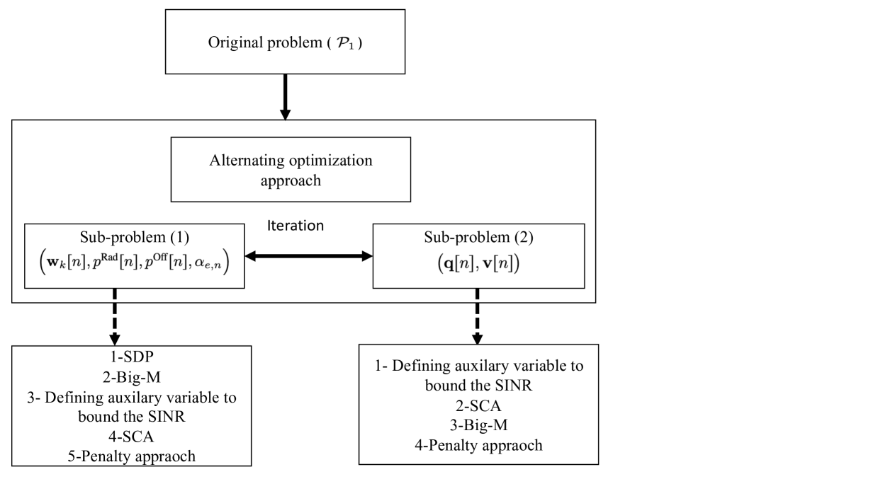
Optimization problem is challenging to solve. The challenge primarily stems from the intricate interplay of various system parameters and the non-convexity introduced by constraints C5, C11, C12, and the UAV’s power consumption model in the objective function. Moreover, the inclusion of binary sensing indicator in C1-C5, C8, C11, and C12 transforms the optimization problem into an MINLP problem, further enhancing its complexity. Additionally, satisfying the equality constraint C12 poses a significant challenge in efficiently solving the formulated problem. The presence of UAV trajectory variables in the exponential functions in the steering vectors aggravates the difficulty of the joint UAV trajectory and beamforming optimization problem. Consequently, finding a globally optimal solution in polynomial time for this problem is a formidable task. The problem involves multiple variables and constraints, making it inherently complex. By decomposing it into two sub-problems, we break down the complexity, promoting a manageable and efficient solution. Thus, to strike a balance between computational complexity and performance, we propose a suboptimal solution approach using an iterative algorithm based on the AO technique. Beamforming for the communication users, the power of the sensing beam, the power for offloading along with binary sensing indicators are primarily related to communication and sensing aspects. These variables can be optimized relatively independently of the UAV’s trajectory and velocity. Separating these aspects into a sub-problem enables parallelization, potentially speeding up the overall optimization process. Therefore, in a first step, we jointly optimize the communication and sensing variables, using a combination of semi-definite programming (SDP), Big-M method, SCA, and the penalty approach. Then, in a second step, we jointly optimize the UAV trajectory and velocity, utilizing SCA, Big-M, and the penalty approaches. Despite being suboptimal, this approach simplifies the problem and allows us to significantly reduce power consumption while meeting the prescribed communication and sensing performance requirements. The key steps for finding the solution to the considered overall optimization problem are illustrated in Figure 3.
IV-A First Sub-Problem
First, we assume that the position and velocity of the UAV are fixed, and we aim to optimize the remaining variables. To do so, we employ SDP and define , , where and . One obstacle to solving optimization problem is the coupling of with , , and in C1-C4. In order to overcome this difficulty, we adopt the big-M formulation. In particular, we define the new optimization variables, , , , and add the following additional constraints to the optimization problem:
| (21) | |||
| (22) |
| (23) | |||
| (24) | |||
| (25) | |||
| (26) | |||
| (27) |
Besides, we introduce a set of auxiliary optimization variables to bound the SINR from below[21, 22]
| (28) |
However, (28) is still non-convex. To overcome this issue, by introducing auxiliary variable , we can rewrite as follows:
| (29) | ||||
| (30) |
The left-hand side of (29) is convex. However, the right-hand side is a product of two terms and is not convex. Nevertheless, we can rewrite the product of the two terms as
| (31) |
Note that (31) is a difference of convex (DC) functions [23]. As a result, the first-order Taylor approximation can be adopted to obtain a convex function and can be bounded as follows:
| (32) |
where denotes the iteration index for SCA. Next, we relax the integer constraint and rewrite C11 as follows:
| (33) |
Constraint C11b is a DC function, and we use first-order Taylor approximation to convert the non-convex constraint to the following convex constraint
| (34) |
Now, we introduce a penalty factor to move constraint to the objective function. represents the relative importance of recovering binary values for . For a sufficiently large value of , optimization problem is equivalent to the following optimization problem [24]:
| s.t. | ||||
| (35) |
where . Constraint C2c is still non-convex. The non-convexity in constraint C2c is due to the multiplicative integer variable with continuous value on the left-hand side of the second part of this constraint i.e., and the difference between two logarithm functions. To tackle this constraint, we define
| (36) |
Now, by exploiting auxiliary variable , we can rewrite (36) as follows:
| (37) |
The left-hand side of (37) is convex. However, the right-hand side is a product of two terms and is not convex. We treat this constraint in a similar way as (31) and (IV-A). As a result, constraint C2c can be rewritten as
| (38) |
The left-hand side of (38) is a difference of two concave functions which is not generally concave. Hence, we employ a first order Taylor approximation to obtain a concave function, i.e., is bounded as follows:
| (39) |
The next challenge is addressing the requirements of equality constraint C12. C12 enforces the exact alignment between the UAV and the specified target position, which may slow down the speed of convergence of the proposed iterative algorithm. To overcome this limitation, we introduce a penalty function to relax the strictness of the constraint during the iterative process, making it more flexible and facilitating convergence. Following the principles of the penalty method, we modify C12 to , i.e., and introduce a penalty function into the objective function, penalizing constraint violations with a coefficient [24]. As a result, the optimization problem at hand can be rewritten as
| s.t. | |||
| (40) |
where is the new set of optimization variables. Now, by dropping the rank-one constraint on and adopting SDP relaxation, problem becomes a convex optimization problem and can be efficiently solved by CVX. The tightness of the SDP relaxation can be proved following similar steps as in [25, Appendix A]. We omit the proof here due to lack of space.
IV-B Second Sub-Problem
In the subsequent step of our proposed solution, the trajectory and velocity of the UAV are designed. Optimal trajectory design poses a challenge as the UAV’s position affects the steering verctor, rendering the problem intractable. Additionally, the complexity is increased by the non-convex nature of the data rate constraint in C2, a pivotal component of our optimization problem. Despite these challenges, we derive a high-quality suboptimal solution. To this end, we introduce new auxiliary optimization variables and to effectively bound the SINR. This transformation allows us to reframe C2 into a set of equivalent constraints. Consequently, C2 is equivalently replaced by the following constraints
| (41) | |||
| (42) |
where . The right-hand side of (41) is not a convex function. Similarly as in (IV-A), by adopting the first-order Taylor approximation we obtain a convex function as , where denotes again the SCA iteration index. The left-hand side of (41) is also a non-convex function of the UAV’s position . Nevertheless, we can rewrite the left-hand side of (41) as follows
| (43) |
where is the element in the row and column of . Besides, and denote the magnitude and phase of , respectively. Note that since the right-hand side of (41) is convex, we need to find an affine approximation of to convexify the underlying optimization problem, which is done via a first-order Taylor approximation as follows
| (44) |
where gradient is given by
| (45) |
By substituting (44), (41) can be restated as follows
| (46) |
Similarly, the left-hand side of (42) can be approximated by its first-order Taylor series. As a result, the inequality in (42) can be restated as
| (47) |
Finally, we deal with the non-convexity of the power consumption of a moving UAV. To do so, we introduce the auxiliary variable , such that
| (48) |
which can be rewritten as
| (49) |
Consequently, the second term in the aerodynamic power consumption during UAV flight can be restated as . Hence, the total aerodynamic power consumption during UAV flight can be restated as =. With the above manipulations, the optimization problem is recast as follows
| s.t. | ||||
| (50) | ||||
Problem is still non-convex due to non-convex constraints C2c, C4, C5, and C26. We address C2c by applying a similar approach as in (IV-A). Moving on to C4, this constraint can be equivalently restated as follows:
| (51) |
where represents a sufficiently large value. The value of should be chosen large enough to ensure that the constraint is always fulfilled for . Finally, SCA can be used to effectively handle constraint C26 by deriving a corresponding global lower bound at a given local point. As a result, based on the first-order Taylor approximation of the right-hand side of C26, the following global lower bound can be obtained
| (52) |
where and are the values obtained in the -th iteration of SCA. This leads to the following convex optimization problem
| s.t. | ||||
| (53) |
In each iteration , we update the solution set and efficiently solve via CVX.
IV-C Overall Algorithm
The proposed solution based on AO is summarized in Algorithm 1. Note that for sufficiently large penalty factors , , in and , the objective function of is non-increasing in each iteration of Algorithm 1 and converges to a high-quality suboptimal solution with polynomial time computational complexity [26]. The computational complexity of Algorithm 1 is given by , where is the big-O notation and is the convergence tolerance of Algorithm 1.
1. Initialize , , , , , , , , (iteration index), .
Repeat
2. Solve for given , and obtain , , and .
3. Solve for given , , , and obtain , .
5. Set
6. until .
| Noise power | dBm | |
| Time horizon | s | |
| Duration of one time slot | s | |
| Maximum transmit power at the UAV | dBm | |
| Required achievable rate of users | bits/s/Hz | |
| RCS | m2 | |
| Minimum long-term sensing SNR at the UAV | dB | |
| Number of antennas at the UAV | ||
| Antenna gain | dBi | |
| Fronthaul link capacity (rate of production) | bits/s/Hz | |
| Number of bits for quantizing echoes | ||
| Number of rounds in sensing phase | ||
| Sensing resolution | m [27] | |
| Fronthaul link bandwidth | MHz [27] | |
| Pulse width | s | |
| Listening time | s | |
| Beamwidth of the ideal beam pattern | ||
| Convergence tolerance | ||
| Penalty factors | ||
| UAV maximum acceleration | ||
| PRF | Pulse repetition frequency | kHz [27] |
| Hardware architecture | [28] | |
| Local computation resource at the UAV | GHz [28] |
V Simulation Results
In this section, we evaluate the performance of the proposed algorithm via computer simulations. We consider an area of km km with communication users and sensing targets. The UAV is equipped with antennas and we set the minimum long-term sensing SNR at the UAV to dB [11]. Furthermore, the UAV operates at an altitude of meters with a maximum flight speed of m/s. Additionally, the channel power gain at the reference distance of meter is dB. The adopted simulation parameters are given in Table II. To investigate the power saving achieved by the proposed scheme, we compare it with two baseline schemes. For baseline scheme 1, we adopt a heuristic trajectory design for the UAV. In particular, the UAV visits each communication user and sensing target along the shortest path while the beamformers, sensing power, sensing indicator, and velocity are optimized. For baseline scheme 2, we adopt zero-forcing beamforming for information transmission and a fixed velocity i.e., m/s, omitting constraint C9. Then, we jointly optimize the communication and sensing power, sensing indicator, and trajectory using a modified version of .
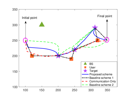
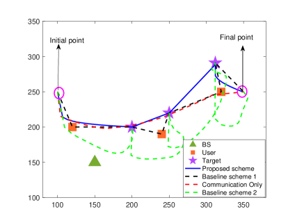

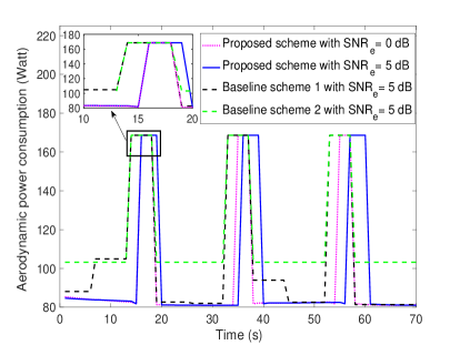
Figs. 4(a) and 4(b) depict the trajectory of the UAV during its mission for different positions of the ground BS. In particular, for the proposed scheme, the UAV starts flying from the initial point towards the location of the first sensing target while transmitting data to the communication users. Fig. 4(c) shows that, during this time, the UAV also adjusts its velocity to minimize power consumption. When approaching the first sensing target, the UAV gradually reduces its velocity to zero before hovering above the target for sensing. Subsequently, the UAV proceeds to the second target, executing another hover-and-sense operation. This pattern continues as the UAV navigates to the third target. In the intervals between the target locations, the UAV dynamically adjusts its trajectory and beamforming vectors to ensure continuous communication, while meeting the data rate requirements of the communication users. As the mission nears completion, the UAV heads towards its final destination while continuing to support the communication users. It is worth noting that the UAV’s trajectory exhibits curvature. This is because in order to save power, the UAV aims to fly at the optimal velocity, while properly adjusting its distance to both the users and the BS for efficient information transmission. Figs. 4(a) and 4(b) also include the trajectories of the UAV when there is no sensing requirement. In this case, the UAV conserves power by navigating between the users, while supporting multiple users simultaneously. From Fig. 4(c), we can observe that for baseline scheme 1, as the trajectory is not optimized, the UAV needs to fly with a higher velocity to complete its mission. This results in increased aerodynamic power consumption, as illustrated in Fig. 4(d). Another interesting observation is that the proposed algorithm leads to shorter hovering times compared to baseline schemes 1 and 2. Because of the joint optimization of the sensing indicator, beamformers for information transmission, sensing power, trajectory, and UAV velocity, less time is needed to complete the sensing tasks. Moreover, as the sensing requirements become more stringent, the required UAV hovering time increases. This increase in hovering time, in turn, leads to a corresponding rise in the aerodynamic power consumption of the UAV. A comparison of Figs. 4(a) and 4(b) reveals the influence of the location of the ground BS on the UAV’s trajectory. In fact, the UAV strives to maintain close proximity to the BS throughout its mission. This behavior is caused by constraints C4 and C5, which ensure real-time information exchange between the UAV and BS. Consequently, during each time slot, the UAV flies as close as possible to the ground BS, enhancing the reliability of the connection.
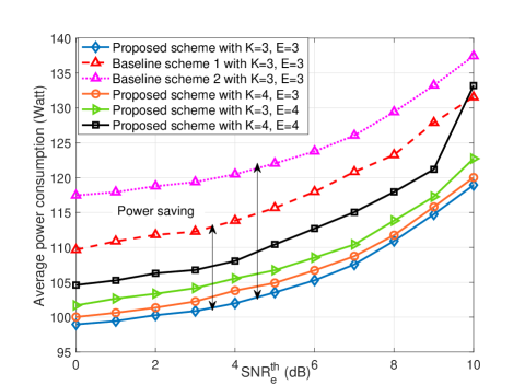
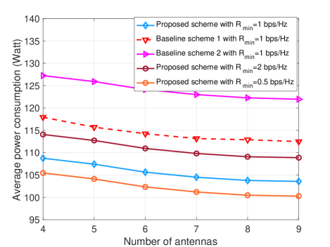
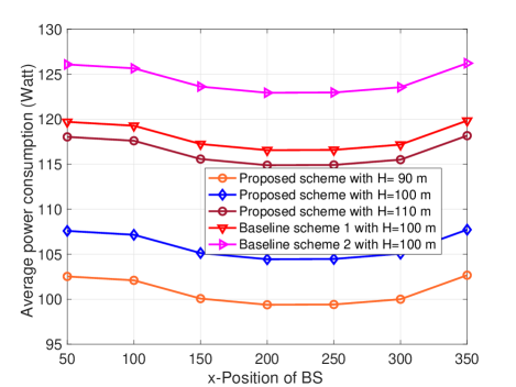
Fig. 5 shows the average power consumption versus the sensing SNR requirement. The average power consumption of the UAV for both the proposed scheme and the baseline schemes increases monotonically with the minimum SNR threshold for sensing. This escalation occurs because, in order to meet more stringent sensing requirements, the UAV must not only transmit with higher power but also dedicate more time to hovering. Furthermore, Fig. 5 highlights the longer impact of the number of sensing targets on power consumption compared to the number of communication users. This is primarily attributed to two factors. Firstly, sensing tasks necessitate higher transmission power because of the round-trip pathloss, thereby increasing power consumption. Secondly, our proposed scheme requires UAV hovering during sensing, which consumes more power compared to the flight mode. These factors collectively highlight the significant role of the sensing tasks on power consumption. Nevertheless, the average power consumption does increase with the number of communication users. This increase can be attributed to the UAV-mounted transmitter needing to allocate more degrees of freedom (DoFs) to mitigate multi-user interference (MUI). However, this diminishes the flexibility in trajectory and beamforming design, ultimately resulting in performance degradation. The impact of velocity and trajectory optimization on UAV power consumption is also evident in Fig. 5. Specifically, the proposed scheme, leveraging trajectory design to provide additional DoFs, consumes less power compared to baseline scheme 1 with a fixed trajectory. Likewise, baseline scheme 2 incurs a higher power consumption due to both a fixed beamforming policy, leading to increased transmit power, and a fixed UAV velocity leading to an increased aerodynamic power consumption.
Fig. 6 shows the average power consumption versus the number of antennas at the UAV for different minimum data rate requirements, denoted as . As can be seen, the average UAV power consumption decreases with increasing number of transmit antennas. This is because the extra DoFs offered by the additional antennas facilitate more precise beamforming and can efficiently mitigate MUI. However, as the number of antennas increases, the performance gains decreases, suggesting reduced marginal benefits. In this context, it is essential to note the impact of the circuit power consumption. While additional antennas can improve beamforming, the resulting reduction in power consumption are counteracted by the additional circuit power required. This trade-off suggests that, beyond a certain point, the increase in circuit power consumption may outweigh the beamforming gains achieved with additional antennas. We also observe a notable difference in power consumption between the proposed scheme and the two baseline schemes. Specifically, in baseline scheme 2, the fixed information beamforming policy leads to an increased transmit power. This is because the scheme fails to fully exploit the spatial DoFs. Moreover, a substantial amount of power is consumed during the UAV’s flight in baseline scheme 2, which is attributed to the fixed velocity of the UAV, resulting in elevated aerodynamic power consumption. As a consequence, baseline scheme 2 exhibits higher overall power consumption compared to the proposed scheme. Additionally, Fig. 6 reveals that the average power consumption increases as the minimum quality of service requirement () becomes more stringent. This is because to satisfy a stricter minimum required data rate, the UAV needs to increase its transmit power, resulting in higher power consumption.
Fig. 7 shows the impact of the position of the BS on the average power consumption, considering different heights of the UAV. In particular, the BS is fixed on the y-axis at m, while it is moved along the x-axis from m to m. As can be observed, the average power consumption of the UAV decreases as the BS moves along the x-axis until it reaches m. This reduction is attributed to the closer proximity of the BS to the first and second sensing targets, requiring less power for data offloading when the UAV visits these targets. Notably, at m and m, where the BS is close to the first and second targets, respectively, the UAV can transmit with lower power during offloading. Conversely, for m, where the distance to the first and second targets is higher, more transmit power is required to ensure successful data offloading. Furthermore, the proposed algorithm demonstrates superior power efficiency compared to both baseline schemes. Additionally, we observe from Fig. 7 that as the UAV’s altitude increases, two key effects come into play: the vertical distance to the targets increases, demanding more power for precise sensing, and the distance to both the communication users and the BS also grows, requiring a higher transmit power to meet the QoS constraints of the users and successful offloading.
VI Conclusion
In this paper, we studied the joint resource allocation and trajectory design for a multi-user, multi-target UAV-based ISAC system, where we accounted the limited capacity of the backhaul link, which is needed for offloading the sensing data to the BS. To avoid interference between sensing and communication, sensing and communication were performed in orthogonal time slots, where the time of sensing was optimized. To be compatible with practical UAV-based sensing systems, pulse radar-based sensing was carried out during UAV hovering. Taking into account the application of a focused sensing beam with small sidelobes, a minimum required accumulated sensing SNR, and UAV hovering during sensing, we minimized the average power consumption of the UAV while ensuring the QoS for both the communication users and the sensing tasks. To solve the resulting challenging non-convex MINLP, we developed a computationally efficient AO-based algorithm, which yielded a high-quality suboptimal solution. Our simulation results revealed that 1) the proposed design enables substantial power savings compared to two baseline schemes; 2) more stringent sensing requirements lead to longer sensing times, highlighting the trade-off between sensing accuracy and sensing time; 3) the number of sensing targets has a larger impact on power consumption than the number of communication users; 4) data offloading can be improved by positioning the BS closer to the sensing targets; 5) the optimized trajectory design ensures precise hovering above the target during sensing, facilitating high-quality sensing with energy-focused beams; and 6) the designed UAV trajectory balances the distance of the UAV to the communication users and the BS.
References
- [1] A. Khalili, A. Rezaei, D. Xu, and R. Schober, “Energy-aware resource allocation and trajectory design for UAV-enabled ISAC,” Proc. IEEE Globecom, 2023.
- [2] F. Liu, Y. Cui, C. Masouros, J. Xu, T. X. Han, Y. C. Eldar, and S. Buzzi, “Integrated sensing and communications: Toward dual-functional wireless networks for 6G and beyond,” IEEE J. Select. Areas Commun., vol. 40, no. 6, pp. 1728–1767, Jun. 2022.
- [3] F. Liu, C. Masouros, A. Li, H. Sun, and L. Hanzo, “MU-MIMO communications with MIMO radar: From co-existence to joint transmission,” IEEE Trans. Wireless Commun., vol. 17, no. 4, pp. 2755–2770, Apr. 2018.
- [4] X. Liu, T. Huang, N. Shlezinger, Y. Liu, J. Zhou, and Y. C. Eldar, “Joint transmit beamforming for multiuser MIMO communications and MIMO radar,” IEEE Trans. Signal Process., vol. 68, pp. 3929–3944, Jun. 2020.
- [5] L. Gupta, R. Jain, and G. Vaszkun, “Survey of important issues in UAV communication networks,” IEEE Commun. Surveys Tuts., vol. 18, no. 2, pp. 1123–1152, Nov. 2015.
- [6] D. Xu, Y. Sun, D. W. K. Ng, and R. Schober, “Multiuser MISO UAV communications in uncertain environments with no-fly zones: Robust trajectory and resource allocation design,” IEEE Trans. Commun., vol. 68, no. 5, pp. 3153–3172, May. 2020.
- [7] Q. Wu et al., “A comprehensive overview on 5G-and-beyond networks with UAVs: From communications to sensing and intelligence,” IEEE J. Select. Areas Commun., vol. 39, no. 10, pp. 2912–2945, Oct. 2021.
- [8] K. Meng, Q. Wu, J. Xu, W. Chen, Z. Feng, R. Schober, and A. L. Swindlehurst, “UAV-enabled integrated sensing and communication: Opportunities and challenges,” IEEE Wireless Communications, pp. 1–9, 2023.
- [9] Z. Lyu, G. Zhu, and J. Xu, “Joint maneuver and beamforming design for UAV-enabled integrated sensing and communication,” IEEE Trans. Wireless Commun., vol. 22, no. 4, pp. 2424–2440, Apr. 2023.
- [10] K. Meng, Q. Wu, S. Ma, W. Chen, and T. Q. S. Quek, “UAV trajectory and beamforming optimization for integrated periodic sensing and communication,” IEEE Wireless Commun. Letts., vol. 11, no. 6, pp. 1211–1215, Mar. 2022.
- [11] K. Meng, Q. Wu, S. Ma, W. Chen, K. Wang, and J. Li, “Throughput maximization for UAV-enabled integrated periodic sensing and communication,” IEEE Trans. Wireless Commun., vol. 22, no. 1, pp. 671–687, Jan. 2023.
- [12] Z. Wei, F. Liu, D. W. K. Ng, and R. Schober, “Safeguarding UAV networks through integrated sensing, jamming, and communications,” in Proc. IEEE ICASSP, 2022, pp. 8737–8741.
- [13] Y. Xu, T. Zhang, Y. Liu, and D. Yang, “UAV-enabled integrated sensing, computing, and communication: A fundamental trade-off,” IEEE Wireless Commun. Letts, 2023.
- [14] Y. Rong, R. Gutierrez, K. V. Mishra, and D. W. Bliss, “Noncontact vital sign detection with UAV-borne radars: An overview of recent advances,” IEEE Veh Technol. Mag., vol. 16, no. 3, pp. 118–128, Sep. 2021.
- [15] K. Meng, Q. Wu, J. Xu, W. Chen, Z. Feng, R. Schober, and A. L. Swindlehurst, “UAV-enabled integrated sensing and communication: Opportunities and challenges,” IEEE Wireless Communications, 2023.
- [16] P. Stoica, J. Li, and Y. Xie, “On probing signal design for MIMO radar,” IEEE Trans. Signal Process, vol. 55, no. 8, pp. 4151–4161, 2007.
- [17] M. I. Skolnik, “Introduction to radar,” Radar Handbook, vol. 2, p. 21, 1962.
- [18] J. Lu, T. Tian, Y. Tang, and B. Tang, “Performance analysis of data transmission for joint radar and communication systems,” Mathematical Problems in Engineering, vol. 2021, pp. 1–14, 2021.
- [19] T. Q. Dinh, J. Tang, Q. D. La, and T. Q. Quek, “Offloading in mobile edge computing: Task allocation and computational frequency scaling,” IEEE Trans. Commun, vol. 65, no. 8, pp. 3571–3584, 2017.
- [20] Y. Zeng, J. Xu, and R. Zhang, “Energy minimization for wireless communication with rotary-wing UAV,” IEEE Trans. Wireless Commun., vol. 18, no. 4, pp. 2329–2345, Apr. 2019.
- [21] A. Rezaei, A. Khalili, J. Jalali, H. Shafiei, and Q. Wu, “Energy-efficient resource allocation and antenna selection for IRS-assisted multicell downlink networks,” IEEE Wireless Commun Letts, vol. 11, no. 6, pp. 1229–1233, Mar. 2022.
- [22] D. Xu, X. Yu, D. W. K. Ng, A. Schmeink, and R. Schober, “Robust and secure resource allocation for ISAC systems: A novel optimization framework for variable-length snapshots,” IEEE Trans. Commun., vol. 70, no. 12, pp. 8196–8214, Dec. 2022.
- [23] A. Khalili, E. M. Monfared, S. Zargari, M. R. Javan, N. M. Yamchi, and E. A. Jorswieck, “Resource management for transmit power minimization in UAV-assisted RIS HetNets supported by dual connectivity,” IEEE Trans. Wireless Commun., vol. 21, no. 3, pp. 1806–1822, Mar. 2022.
- [24] J.-F. Bonnans, J. C. Gilbert, C. Lemaréchal, and C. A. Sagastizábal, Numerical optimization: theoretical and practical aspects. Springer Science & Business Media, 2006.
- [25] X. Yu, D. Xu, D. W. K. Ng, and R. Schober, “IRS-assisted green communication systems: Provable convergence and robust optimization,” IEEE Trans. Commun., vol. 69, no. 9, pp. 6313–6329, Sep. 2021.
- [26] J. C. Bezdek and R. J. Hathaway, “Some notes on alternating optimization,” in AFSS Int. Conf. Fuzzy Systems. Springer, 2002, pp. 288–300.
- [27] C. Schwartz, T. Bryant, J. Cosgrove, G. Morse, and J. Noonan, “A radar for unmanned air vehicles,” The Lincoln Laboratory Journal, vol. 3, no. 1, pp. 119–143, 1990.
- [28] Z. Yu, Y. Gong, S. Gong, and Y. Guo, “Joint task offloading and resource allocation in UAV-enabled mobile edge computing,” IEEE Internet of Things Journal, vol. 7, no. 4, pp. 3147–3159, 2020.