linecolor=black,linewidth=0.5pt
Characterization of
Lightweight GPS Disciplined Oscillators for
Distributed UAV Measurement Applications
Abstract
With an increasing variety of measurement applications using sensing nodes on unmanned aerial vehicles (UAVs), global positioning system (GPS) and global navigation satellite system (GNSS) disciplined oscillators (GPSDOs, GNSSDOs) are an appealing solution for precise wireless inter-device synchronization. Typically evaluated under laboratory conditions by analyzing the 10 MHz and 1 pulse per second (PPS) reference signal stability, these test methods overlook airborne oscillator performance. This paper characterizes lightweight GNSSDO models for flight suitability using a measurement system based on software defined radios (SDR). We analyze reference signal stability under controlled GNSS signal impairments to predict performance and measurement precision loss in dynamic operational modes. Additionally, we assess behavior under the impacts caused by operating the UAV, as well as typical flight vibrations and accelerations outlined in the standard for payload devices.
Index Terms:
GNSS, GPS disciplined oscillators, GNSSDO, 1 pulse per second (PPS), 10 MHz, reference signal stability, synchronization, unmanned aerial vehicles (UAV), drone, aerial.I Introduction
The growing deployment of UAVs in various measurement applications has emphasized the need for precise timing and synchronization mechanisms, often provided by small, lightweight GNSSDOs. Despite their importance, the performance of GNSSDOs under the dynamic conditions of UAV flights remains inadequately characterized in existing literature.
To address this gap, we introduce a comprehensive laboratory GNSSDO testbed designed to analyze the stability of 10 MHz and 1 PPS reference signals specifically for UAV applications. We exemplify its capabilities by characterizing the behavior of two oven-controlled crystal oscillator (OCXO)-based GNSSDO models for short set-up times, in steady state, during GNSS signal impairments, under mechanical disturbances, and under the influence of UAV electronics.
II GNSSDO testbed
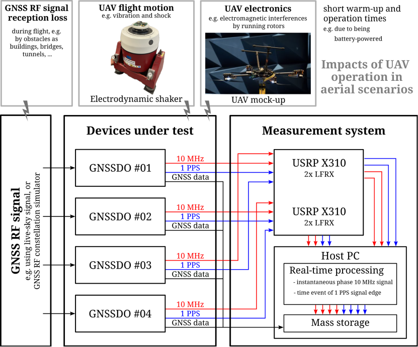
To comprehensively assess and enhance the performance of GNSSDOs for the utilization in UAV applications, it is essential to precisely analyze the time error between 10 MHz and 1 PPS reference signals concurrently among multiple oscillators, while considering GNSS signal quality and the distinct effects encountered during flight. We realized this by extending our GNSSDO testbed [1] with an electrodynamic vibration test system and a quadcopter mock-up, as shown in Fig. 1.
II-1 Time and frequency stability measurement system
Our measurement system supports simultaneous analysis of 1 PPS and 10 MHz reference signal stability using only commercial off-the-shelf (COTS) components and digital signal processing (DSP) software [2]. Its most recent hardware iteration comprises two USRP X310 from Ettus Research™ and enables to characterize the performance of up to four GNSSDOs with sub-nanosecond precision [1].
II-2 Electrodynamic vibration test system
The vibration test system is based on the electromechanical Shaker V300 from Data Physics™[3], which allows to accelerate payload with up to 98g and a maximum sine force of 1646 N in a frequency range from 0 to 5000 Hz and a shock force of up to 3490 N.
II-3 Quadcopter mock-up
To emulate the impact of UAV electronics on GNSSDOs, a fully operational and remotely controllable drone mock-up with a cabled power supply is needed to expose the device under test (DUT) to reproducible and repeatable conditions, enabling automated long-term measurement cycles. The presented mock-up is built upon a Tarot Iron Man FY650 frame with a diameter of 650 mm using the propulsion system DJI E800, making it comparable in size and motors to DJI’s 3–4 kg camera drones, such as the DJI Inspire I. Customized control electronics enable reliable thrust settings provided to the electronic speed controllers of individual rotors by periodic pulses with widths between 1100 µs at 0 and 2000 µs at 100 [4].
III Evaluation of GNSSDO performance
To showcase the functionality of the introduced GNSSDO testbed, two devices from each of two widely-used, low-cost, lightweight, OCXO-based GNSSDO models available to the authors are characterized in terms of their reference signal stability in different operation modes. These GNSSDO models, namely the Jackson Labs GPSDO LCXO OCXO [5] and the Furuno Multi-GNSSDO GF-8805 [6], were selected because of their promising values in terms of weight, spatial dimensions, power consumption, and reference signal stability specified in the data sheets. For the presented measurement data, all DUTs are subjected to the same live-sky GNSS scenario using a stationary, exposed antenna position with clear sky view on the rooftop of a laboratory building.
III-A Reference signal stability in steady-state
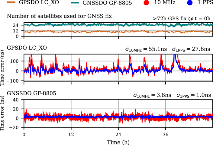
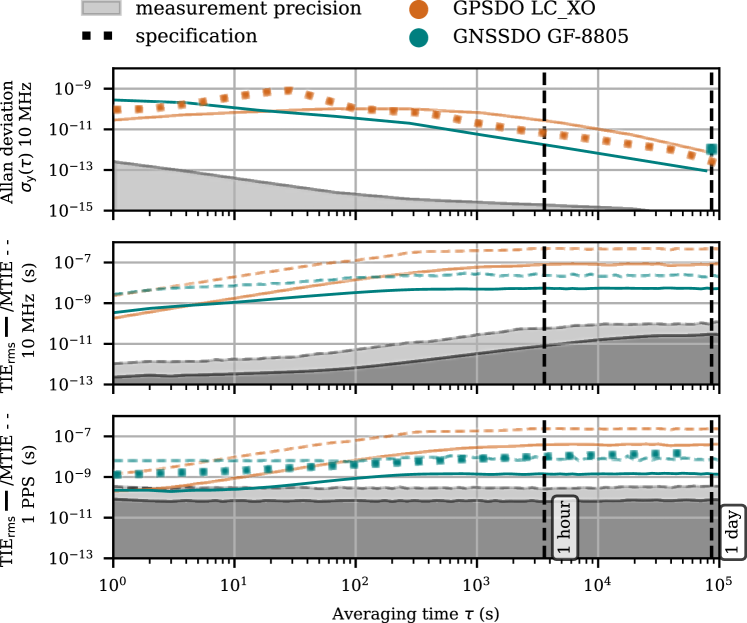
In order to enable the selection of GNSSDO devices from the multitude of models on the market, the reference signal stability of oscillators in steady-state under laboratory conditions is specified in data sheets and academic research using the statistical time-domain metrics Allan deviation and time interval error (TIE) in form of its maximum (MTIE) and root-mean-square (RMS) value TIErms. As presented in Fig. 2, after being locked for more than 72 hours to the timing information derived from the GNSS signals, the time errors of the GNSSDO models under test show clear differences within an order of magnitude. The time error between the 1 PPS reference signals provided by the GPSDO model LCXO is strongly affected by outliers and varies with a standard deviation of up to 28 ns, whereas the GF-8805 provides 1 PPS signals with a time error of only up to 1 ns. As shown in Fig. 3, the short-term stability of the 10 MHz and 1 PPS reference signals provided by the GNSSDO GF-8805 is worse than that of the GPSDO LCXO, but outperforms the LCXO for long-term observation intervals. The maximum time error of both reference signal types provided by the LCXO exceeds 100 ns over a time interval of 30 minutes, which matches a common flight duration, whereas for the GF-8805 the corresponding MTIE is only 10 ns for the provided 1 PPS reference signals and 25 ns for the 10 MHz reference signals.
III-B GNSSDO performance for short set-up times
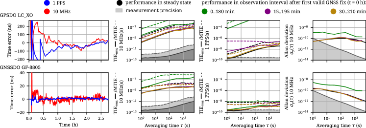
In addition to the performance during steady-state operation, certain measurement applications, particularly those utilizing battery-powered systems as it is common in UAV scenarios, necessitate the GNSSDOs to be set up shortly before usage, thus requiring examination of their performance in the stabilization interval following a cold start. As depicted in Fig. 4, the 10 MHz and 1 PPS reference signals provided by both GNSSDO models under test exhibit noticeable settling drift. To ascertain the duration between the initial valid GNSS fix and the effective usability for a specific measurement use case, it is necessary to evaluate the influence of oscillator settling on the resultant time error. Comparing the reference signal stability of the DUTs in steady-state with the stability of devices affected by settling behavior, as shown in Fig. 4, in terms of Allan deviation and TIE, it becomes apparent that the GF-8805 requires up to 15 min to stabilize. The LCXO needs at least 30 min to stabilize and provide acceptable reference signals.
III-C Oscillator behavior during GNSS signal impairment
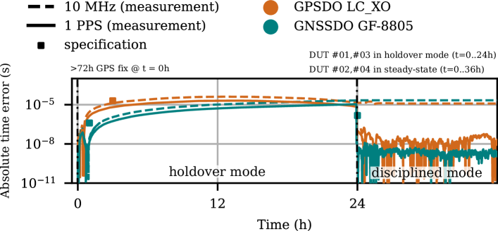
GNSS signal impairments, e.g., line-of-sight obstruction by buildings, bridges, or vegetation, are inherent to non-stationary GNSSDO applications. Typical devices provide only limited information on their output reference signal quality or require to infer the output signals’ accuracy from GNSS signal quality metrics. To select suitable GNSSDOs based on performance with impaired GNSS signal, both holdover behavior and the return to disciplined mode must be analyzed. The resulting time error during the absence of GNSS signals depends mainly on the GNSSDO’s implementation to bridge the reference signals until the next GNSS fix, as shown in Fig. 5 and Tab. I. For both OCXO-based GNSSDO models under test, the time error of the 10 MHz and 1 PPS reference signals increases strongly during a GNSS signal loss. After being re-disciplined the 1 PPS reference signals of both models recover the timing accuracy before the GNSS signal outage, while the drift of the 10 MHz signals accumulated during the holdover operation results in a significant time error offset.
Maximum time error (s)
GNSSDO
@ 15min
@ 30min
@ 1h
@ 3h
@ 12h
@ 24h
LCXO
0.2
0.3
2.9
13.4
40.9
41.3
GF-8805
0.1
0.2
0.2
1.1
10.4
21.9
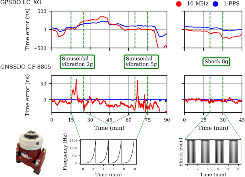
III-D GNSSDO performance under mechanical disturbances
To mitigate the impact of flight motions on UAV-mounted devices, countermeasures are necessary. To reduce development effort and costs, while considering UAV payload weight and space constraints, examining these mechanical effects on GNSSDO model performance is beneficial. Fig. 6 exemplifies the time error between reference signals of one GNSSDO per model in steady-state and one DUT per model influenced by conditions of UAV operation in form of vibration and shock parameters outlined in standard requirements for UAV payload devices [7]. It is apparent that the reference signal stability of both GNSSDO types is affected by the sinusoidal vibrations during the exposure. Additionally, the GPSDO LCXO shows strong drifting behavior for both reference signals after the end of the mechanical exposure.
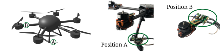
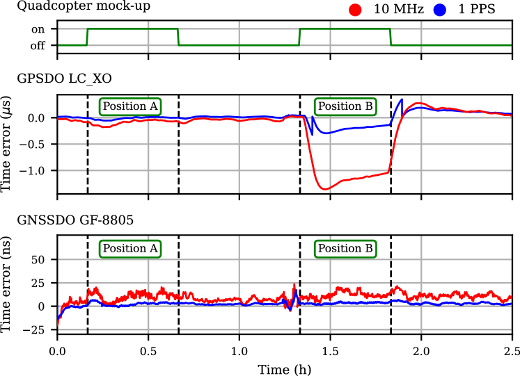
III-E Reference signal stability during UAV mock-up operation
Due to strict space and weight limits for UAV payload, determining device placement and the necessity for additional electromagnetic shielding are crucial considerations when planning applications with participating UAV nodes. The quadcopter mock-up shown in Fig. 1 can be used to exemplify the impact of the UAV electronics on the reference signal stability of the GNSSDOs under test for different positions during flight. Two extreme placement options were tested: Position (A) is located at the bottom of the potential payload space to maximize the distance between the DUTs and the running rotors with their power supply cables, whereas position (B) is chosen to place the DUTs as close to the rotors as possible. The motor thrust values provided to the electronic speed controller of the UAV mock-up were chosen to alternate every 20 seconds between periodic pulse widths of 1500 µs and 1600 µs to emulate a real flight scenario with straight motion vectors interrupted by changes in direction. The time error between the reference signals of one GNSSDO under test in steady-state and one influenced by conditions of the operating UAV, as shown in Fig. 7, reveals clear differences in the robustness of the two GNSSDO model types. The GNSSDO model GF-8805 shows no significant outliers during the exposure, whereas the GPSDO LCXO shows outliers and settlement behavior after the end of the exposure corresponding to its distance to the rotors.
IV Conclusion
This paper introduced a laboratory testbed to analyze the 10 MHz and 1 PPS reference signal stability of GNSSDOs for UAV applications. The testbed combines a highly precise SDR- and DSP-based reference signal stability measurement system, an electrodynamic vibration test system, and a UAV mock-up to characterize the performance of up to four DUTs simultaneously. This approach isolates and enables the analysis of the impact of individual effects occurring during UAV flight operations, allows to improve the reference signal stability by targeted countermeasures, and complements specification sheets to aid in the selection of appropriate devices for synchronizing mobile aerial nodes. To demonstrate the testbed’s capabilities, we characterized the reference signal stability of two low-cost, lightweight, OCXO-based GNSSDO model types. This characterization included behavior relative to GNSS signal reception quality in steady-state, warm-up, and holdover mode, as well as conditions of UAV operation. The more affordable of the two GNSSDO models exhibited better signal stability and robustness. However, its larger size and weight limits its suitability for small UAVs.
References
- [1] J. Bauer, C. Andrich, A. Ihlow, N. Beuster, and G. Del Galdo, “Characterization of GPS Disciplined Oscillators Using a Laboratory GNSS Simulation Testbed,” in 2020 Joint Conference of the IEEE International Frequency Control Symposium and International Symposium on Applications of Ferroelectrics (IFCS-ISAF), 2020, pp. 1–4, doi: 10.1109/IFCS-ISAF41089.2020.9234932.
- [2] C. Andrich, A. Ihlow, J. Bauer, N. Beuster, and G. Del Galdo, “High-precision measurement of sine and pulse reference signals using software-defined radio,” IEEE Transactions on Instrumentation and Measurement, vol. 67, no. 5, pp. 1132–1141, May 2018, doi: 10.1109/TIM.2018.2794940.
- [3] G. F. Lang, D. Snyder et al., “Understanding the physics of electrodynamic shaker performance,” Sound and vibration, vol. 35, no. 10, pp. 24–33, 2001.
- [4] P. Kósa, M. Kišev, L. Vacho, L. Tóth, M. Olejár, M. Harnicarova, J. Valíček, and H. Tozan, “Experimental Measurement of a UAV Propeller’s Thrust,” Tehnicki vjesnik - Technical Gazette, vol. 29, 01 2022, doi: 10.17559/TV-20201212185220.
- [5] Jackson Labs Technologies. (2012, 09) GPSDO LCXO manual. [Online]. Available: http://www.jackson-labs.com/assets/uploads/main/LC_XO_Manual.pdf
- [6] Furuno. (2024, 04) Manual - Multi-GNSS Disciplined Oscillator Model GF-8804, GF-8805. [Online]. Available: https://furuno.ent.box.com/s/r4aqpz5bu2otd8ihm2d0e80k11cswcnc
- [7] “IEEE Standard Interface Requirements and Performance Characteristics of Payload Devices in Drones,” IEEE Std 1937.1-2020, pp. 1–30, 2021, doi: 10.1109/IEEESTD.2021.9354136.