∎
e1e-mail: endo.shunsuke@jaea.go.jp
Circular polarization measurement for individual gamma rays in capture reactions with intense pulsed neutrons
Abstract
Measurements of circular polarization of -ray emitted from neutron capture reactions provide valuable information for nuclear physics studies. The spin and parity of excited states can be determined by measuring the circular polarization from polarized neutron capture reactions. Furthermore, the -ray circular polarization in a neutron capture resonance is crucial for studying the enhancement effect of parity nonconservation in compound nuclei. The -ray circular polarization can be measured using a polarimeter based on magnetic Compton scattering. A polarimeter was constructed, and its performance indicators were evaluated using a circularly polarized -ray beam. Furthermore, as a demonstration, the -ray circular polarization was measured in 32S(,)33S reactions with polarized neutrons.
1 Introduction
Measuring the circular polarization of rays emitted from nuclear reactions is used to determine spin correlations. In -ray transitions from excited states formed by neutron capture reactions, the circular polarization of each ray depends on the spin of the excited states and the mixing of the multipolarity in the transitions Biedenharn . Therefore, measuring circular polarization is valuable for studying nuclear structures.
Furthermore, -ray circular polarization in a neutron capture resonance is crucial for studying the enhancement effect of the parity nonconservation (parity-violation) in compound nuclei. A significant enhancement of the parity-violation in the compound nuclear reactions has been observed in longitudinally polarized neutron capture reactions Mitchell . This enhancement results from mixing the s- and p-wave amplitudes, predicted by the s-p mixing model Flambaum . The s-p mixing model also gives a formula for the neutron capture cross-sections considering the angular correlations between neutron momentum, neutron spin, -ray momentum, and -ray spin depending on neutron energy. The angular correlation terms have been measured for several nuclei, such as 139La, 117Sn, and 131Xe Okudaira2018 ; Yamamoto ; Okudaira2021 ; Koga ; Endo2022 ; Okudaira2023 , to verify the s-p mixing model. These correlation terms result from the interference between the s- and p-wave amplitudes predicted by the s-p mixing model. However, they do not include the parity-violating effect caused by mixing those amplitudes. The circular polarization-dependent cross-section is a correlation term equivalent to the parity-violating cross-section caused by the mixing s- and p-wave amplitudes. If parity violation enhancement is based solely on the s-p mixing model, the magnitude of the parity violation measured by circular polarization should be interpreted in a unified manner with the measurement results using polarized neutrons Mitchell . Therefore, circular polarization measurements are significant for validating the s-p mixing model. None-theless, the circular polarization of rays from resonances in the high-energy region of approximately 1 eV or more, called epithermal neutrons, has not been measured.
The -ray circular polarization can be determined by measuring the transmission through a magnetized material, called a -ray polarimeter. Several circular polarization measurements in neutron capture reactions were performed from the 1950s to the 1970s TRUMPY ; Vervier ; KOPECKY ; Djadali ; VENNINK . The -ray polarimeter comprised an iron magnetized by a wrapped coil. These measurements were performed using low-energy neutrons ( meV) from a nuclear reactor to determine the spin of a compound state in thermal neutron energy. However, it is challenging to determine the spin uniquely because the effects of many resonances are mixed in the thermal-neutron energy. In the 2000s, a polarimeter was developed to measure the parity-violation in polarized thermal neutrons and deuteron reactions MikePol . The polarimeter comprised permendur material, which has the strongest saturation magnetization among common magnetic materials. The uses of -ray polarimeters were limited to -rays emitted from thermal neutron capture reactions because no facilities provided highly intense epithermal neutrons.
Recently, highly intense epithermal neutrons have become available because of the development of highly intense pulsed neutron sources. Hence, introducing a polarimeter to pulsed neutron sources makes it possible to measure the circular polarization of rays emitted from resonance states. Therefore, it is possible to perform experiments to determine the spin of resonance states and verify the s-p mixing model. Consequently, we developed a -ray polarimeter that can be used at the Materials and Life Science Experimental Facility (MLF) in the Japan Proton Accelerator Research Complex (J-PARC). The MLF in J-PARC has a pulsed neutron source with one of the highest neutron intensities globally. The Accurate Neutron-Nucleus Reaction Measurement Instrument (ANNRI) is a beamline in the MLF. High-intensity neutrons ranging from a few meV to several keV are available at ANNRI, where (n,) reaction measurements are performed using the installed high-purity germanium (HPGe) detectors. Thus, ANNRI is an ideal instrument for conducting -ray circular polarization measurements that require large statistics.
The polarimeter has two performance indicators: the analyzing power, known as capability in the polarization measurement, and the magnetic hysteresis. The magnetization of the polarimeter must be saturated for circular polarization measurements. In the present study, the -ray transmission was measured as a function of the current applied to the polarimeter using circularly polarized rays at the Ultraviolet Synchrotron Orbital Radiation (UVSOR) facility Katoh . The experimental results on the two performance indicators will be presented.
As a demonstration of the circular polarization measurement of the neutron capture reaction in a pulsed neutron source, the circular polarization of rays was measured in 32S(,)33S reactions at ANNRI. The circular polarization of several individual rays was derived and compared with the theoretical calculation. In this paper, we discuss the circular polarization of -rays produced in the polarized neutron capture of 32S.
2 Gamma-ray Polarimeter
The Compton scattering cross-section including magnetic effect is written as Chesler ; Tolhoek :
| (1) |
where is the electron radius, is the Klein-Nishina Compton scattering cross-section, and are the degrees of the electron polarization and the -ray circular polarization, respectively, and is the angle between the electron spin direction and the -ray momentum direction. is expressed as
| (2) |
where is initial photon energy in units of the electron mass. The second term in Eq. (1), representing the magnetic effect, depends on the -ray circular polarization. Thus, circular polarization can be determined by measuring the -ray transmission of a polarimeter.
Several experiments TRUMPY ; KOPECKY ; VENNINK ; MikePol have used the magnetic Compton scattering to measure -ray circular polarization. A transmission polarimeter was constructed in a manner similar to that used in these studies. However, the size was limited to installation in ANNRI. To improve the analyzing power, the core of the polarimeter comprised a permendur material that provided a high saturation magnetization corresponding to high-electron polarization. Furthermore, the polarimeter included a return yoke to reduce the effect of the magnetic field leakage on the HPGe detector and achieve a high magnetic field. The polarimeter was wound with 500 turns of conductor and operated at a current of 3.98 A. Figure 1 shows a sectional view of the polarimeter.
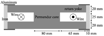
The magnetic field was simulated using computer-aided engineering (CAE) software, Femtet, produced by Murata Software Co., Ltd. Femtet . The average magnetization of the permendur core was estimated to be T at A.
The analyzing power for the -ray circular polarization is calculated as
| (3) |
where and are the transmissions for right- and left-handed circularly polarized rays. The transmission is calculated as , where is the number density of the electrons, is the core length, and
| (4) |
Here, , , and are the cross-sections of the photoelectron effect, coherent scattering, and pair production, respectively. is the Avogadro constant, and is the atomic weight. The magnetization of the polarimeter, , is related to the electron polarization ratio Aulenbacher :
| (5) |
where is the Bohr magneton, is the electron g-factor (), is the g-factor for the permendur (), and is the number density of electrons. The -ray energy dependence of the analyzing power is plotted in Fig. 2. The analyzing power for a 6.6-MeV ray was estimated to be . The change in the analyzing power between 2 and 7 MeV was also estimated to be approximately 6%.
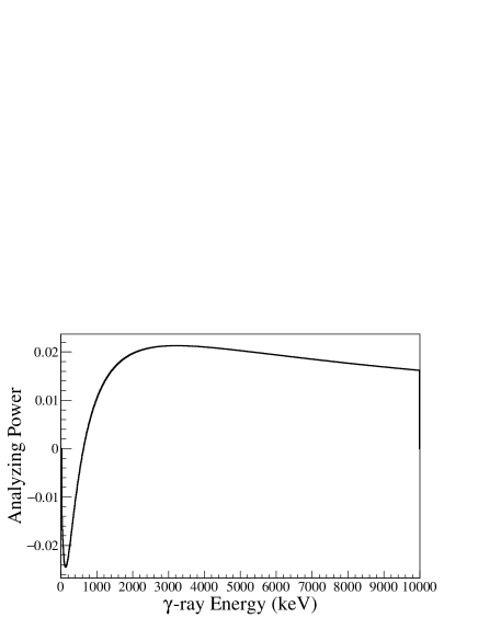
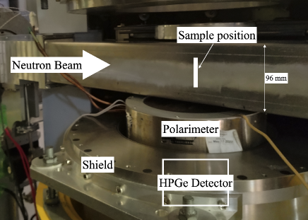
Figure 3 shows a photograph taken after installing the polarimeter at ANNRI. The rays transmitted through the polarimeter were detected using the HPGe detector. The HPGe detector has a hexagonal shape, and the size is approximately 70 mm in diameter and 78 mm in length. The details of the HPGe detector are given in Ref. Takada . The -ray detection efficiency was estimated by considering the transmission of the polarimeter using GEANT4 simulation GEANT4 . The photo peak efficiency was obtained to be for a 5-MeV ray using the same method in Ref. Takada . This efficiency was approximately 0.2 times the detection efficiency without a polarimeter of 0.046% due to the attenuation by the polarimeter. Installing the polarimeter at ANNRI made it possible to measure circular polarization with a full absorption peak efficiency of in a pulsed neutron source for the first time.
3 Measurements of performance indicators for the polarimeter at UVSOR
3.1 Measurement procedure
The transmission of circularly polarized rays was measured at BL1U in the UVSOR Katoh facility to evaluate the analyzing power and magnetic hysteresis. Figure 4 shows the experimental setup.
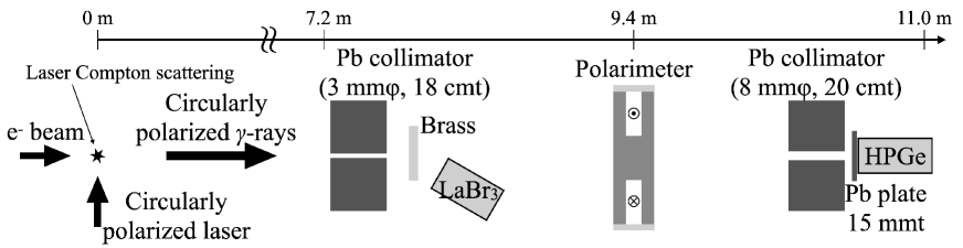
The circularly polarized pulsed -ray beam was produced using laser Compton scattering (LCS). The maximum -ray energy was 6.6 MeV. The details of the generation of circularly polarized rays are provided in Ref. Taira . As a -ray flux monitor, a LaBr3 detector was used to measure the Compton scattered events with a 3-mm-thick brass plate between the collimator and polarimeter. The rays penetrating the polarimeter were detected using an HPGe detector 90.3 mm in diameter and 83.5 mm in length. A lead (Pb) collimator was installed in front of the HPGe detector to reduce the small-angle scattering background in the polarimeter. An additional 15-mm-thick Pb plate was placed in front of the HPGe detector to reduce the pile-up events of the HPGe detector signals. The number of transmitted rays for left- and right-handed circular polarizations was measured by changing the current applied to the polarimeter from A to A. Furthermore, a laser-off measurement was performed to estimate the background from environmental radiation and the Bremsstrahlung of storage electrons.
3.2 Analysis
Figure 5 shows the pulse height spectrum of the LaBr3 detector. The background is the result of the laser-off measurement. The structures from 0.7 to 2.5 MeV results from the self-radioactivity of the LaBr3 detector.

The -ray flux, , was determined using an integral value from 2.0 to 6.7 MeV. The transmitted events were normalized to the incident -ray intensity measured at each current applied to the polarimeter.
Figure 6 shows the -ray energy spectrum of the HPGe detector with the background of laser-off measurement.
The peak around 12 MeV was caused by pile up. The origin of 11.2-MeV peak in the background could not be specified, but it does not affect the results. The total counts of the HPGe detector corrected for pile-up events were obtained using the following procedure. According to Ref. Kondo , the number of pile-up -rays follows a Poisson distribution:
| (6) |
where relates to the average number of rays incident on the HPGe detector per pulse, and is the number of pile-ups. The number of single and double -ray detection events is written as
| (7) |
and
| (8) |
where is the count of the single -ray events, which is the integral value between 200 and 6,620 keV; is the count of the double -ray events, which is an integral value between 7,120 and 13,240 keV. is the detection efficiency. The detection efficiency was estimated to be 80% using an EGS5 simulation. From Eqs. (6)-(8), the parameter, , is obtained as follows:
| (9) |
The total count, considering up to the fourth hit, can be calculated as
| (10) |
where is calculated as
| (11) |
from Eqs. (7) and (8). The corrected count proportional to the transmission of the polarimeter, , was defined as
| (12) |
3.3 Results
The corrected counts, and , for the right- and left-handed circularly polarized -ray beam were obtained from Eq. (12), and the analyzing power was calculated as
| (13) |
based on Eq. (3). Figure 7 shows the analyzing power determined for each current. The closed and opened points indicate whether the measurement was for increasing or decreasing the current of the polarimeter, respectively. The uncertainty was deduced from propagating statistical errors.

A difference at 0 A observed in the analyzing power is due to the effect of magnetic hysteresis.
The analyzing power, saturated above A and below A, was obtained to be and , respectively. The analyzing powers for the positive and negative currents differ by approximately 5% because the internal magnetic field differs slightly, particularly in the return yoke. This effect was considered the systematic uncertainty of the analyzing power, 0.10%. Consequently, the averaged analyzing power was determined as , consistent with the estimated value of described in Sec. 2.
4 Measurements of the circular polarization at ANNRI
4.1 Circular polarization of rays from 32S(,)33S reactions
As a demonstration of circular polarization measurements with a pulsed neutron source, such as the one in MLF, the -ray circular polarization was measured in 32S(,)33S reactions. The circular polarization of rays emitted after a polarized neutron capture reaction is described as Biedenharn
| (14) |
where is the neutron polarization ratio, is the angle between the directions of neutron polarization and the emitted -ray momentum, and is the coefficient calculated from the nuclear spin of the compound state, of the initial state, and of the final state. Since the -value for the transition emitting 5.4-MeV rays in the 32S(,)33S reactions is Konijnenberg , this reaction was used to determine the analyzing power in previous experiments MikePol .
The -ray circular polarization is experimentally obtained as
| (15) |
where is the analyzing power and and are the detected counts for up- and down-polarized neutrons, respectively. The analyzing power has already been determined in the UVSOR experiment, but here it is necessary to consider the effects of the solid angle. Thus, we reevaluated the analyzing power using the 5.4-MeV ray. Moreover, the circular polarization of other rays was obtained and compared with the theoretical calculation.
4.2 Measurement procedure
Figure 8 shows the experimental setup.
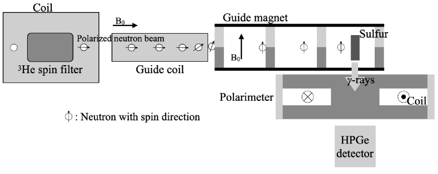
The HPGe detector was at a flight length of 21.5 m. The -ray polarimeter was installed between the HPGe detector and the sulfur sample. In this measurement, the angle, , in Eq. (14) equals for up-polarized neutrons and for down-polarized neutrons. Longitudinally polarized neutrons were produced using a 3He spin filter Okudaira_He , and a guide magnet turned the polarization direction up (down). Li-glass detectors were installed at a flight length of 28.2 m, and transmitted neutrons were measured to correct the neutron polarization and neutron beam intensity. There are two types of Li-glass detectors: 6Li-enriched 6Li-glass and 7Li-enriched 7Li-glass. 6Li-glass has a high sensitivity to neutrons, whereas 7Li-glass has a slight sensitivity to neutrons. The -ray background can be removed by subtracting the spectrum of 7Li-glass from that of 6Li-glass. Natural sulfur powder was pressed and shaped into a 24 mm and 1.3-cm-thick tablet. Total of 28.9 and 29.1 hours were measured for the up- and down-polarization directions, respectively.
Figure 9 shows the time dependence of the neutron polarization ratio and the ratio of the transmitted neutron counts of the 3He spin filter.

The polarization ratio was obtained from the ratio of the transmitted neutron counts of the polarized cell to that of the unpolarized cell. The details of the polarization determination are given in Refs. Yamamoto ; Endo2022 . The ratio of transmitted neutron counts was obtained by dividing the number of events from 3 to 25 meV in the polarized cell by that in the unpolarized cell. Neutron counts at the sample position decrease with time because of the depolarization of 3He nuclei.
4.3 Analysis and results
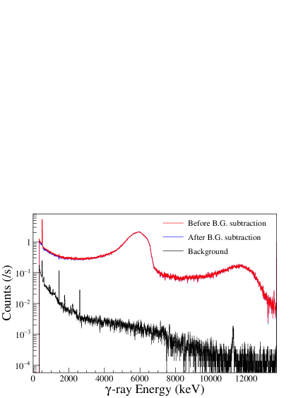
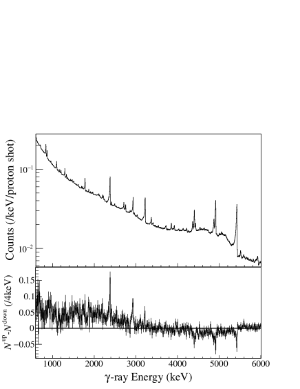
Figure 10 shows the -ray energy spectrum for the up-polarization measurements of gated neutron energy from 3 to 25 meV and the difference between the up- and down-polarization measurements. Besides the 5.4-MeV rays, noticeable differences were observed in some rays, and these are discussed in Sec. 5.
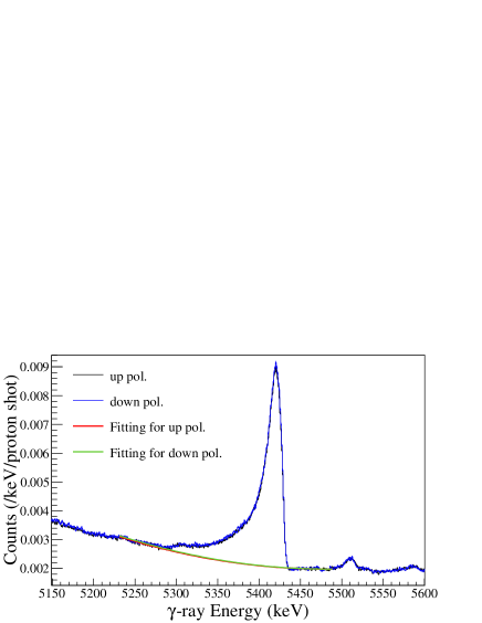
The backgrounds were estimating by a 3-rd polynomial function fit, and the net counts of 5.4-MeV rays were deduced for the full absorption, single escape, and double escape peaks. Figure 11 shows the background fit for the full absorption peak. The net count, , was obtained by subtracting the integral of the fitting result from that of the -ray spectrum. The ranges of the integral regions were defined as the full width at quarter maximum (FWQM).
The asymmetry was defined as
| (16) |
To correct the decreasing beam intensity due to the depolarization of the 3He nuclei and the neutron polarization, the corrected asymmetry was defined as
| (17) |
where and are the neutron polarization. and are the neutron transmissions monitored at the Li-glass detectors for each polarization direction. The neutron transmission corresponds to the neutron beam intensity. Table 1 lists the corrected asymmetries for the 5.4-MeV ray, including the single and double escape peaks. The asymmetry combined with these values was obtained as . The analyzing power was calculated as from Eqs. (14) and (15), and was obtained for the 5.4-MeV rays. Adding the systematic uncertainty due to the difference in the positive and negative currents obtained from the UVSOR experiments, the analyzing power was determined to be .
This result is slightly smaller than the expected value, , from the UVSOR experiments, considering the energy dependence of the analyzing power in Fig. 2. In the ANNRI experiments, since all ray was not incident perpendicular to the polarimeter due to the solid angle of the detector from the sample, the analyzing power was reduced. Therefore, it is necessary to use the results of this sulfur measurement to calibrate the circular polarization measured in ANNRI.
| Peak | Asymmetry () |
|---|---|
| Full absorption | |
| Single escape | |
| Double escape | |
| Averaged value |
5 Discussion of the circular polarization of rays in 32S(,)33S reactions
In this section, we discuss the circular polarization of other -rays in 32S(,)33S reactions.
5.1 Theoretical calculation
When a neutron with an angular momentum of 0 is captured (s-wave resonance), the coefficient in Eq. (14) can be calculated KOPECKY by
| (18) | |||||
where is the coefficient for angular correlations tabulated in Refs. Lawrence ; Alder . , , and are the spins of the initial, compound, and final states, respectively. and are the multipolarity of possibly mixed rays, and is the mixing ratio. In the following, only and are considered. Furthermore, if the -ray transition is via an intermediate state (spin ) by unobserved radiation, Eq. (18) is written Lawrence as
| (19) | |||||
where
| (20) | |||||
where is the Racah coefficient, calculated using the Wigner 6-j symbol as
| (21) |
Here, the mixing of multipolarity in the intervening transition is not considered.
Figure 12 displays the decay scheme, showing only the major transitions from the 32Sn compound state. Table 2 lists the calculated -values with in each transition using Eq. (19). For example, the -value of a 3.2-MeV ray is deduced here. The spins of the initial, compound, intermediate, and final states are , , , and , respectively, and the 5.4-MeV and 3.2-MeV transitions are considered as E1 transitions. Since , , and , the -value becomes .
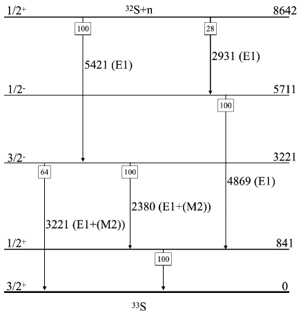
| -ray Energy | from calculation | from experiment |
|---|---|---|
| 5420 keV | -0.5 | (Using Normalization) |
| 3221 keV | 0.33 | |
| 2380 keV | 0.83 | |
| 2930 keV | 1.00 | |
| 4869 keV | -0.33 |
5.2 Comparison with the experimental results
The same analysis for the 5.4-MeV ray in Sec. 4 was applied to the other rays, and the -values for each transition were derived and are listed in Table 2. The integral regions used to derive the net count of the photo peak were defined as FWQM, the same as the 5.4-MeV analysis, however, the full width at half maximum was applied to the 4.9-MeV ray because the peak count was low. In the derivation of the values, the analyzing power was calculated using the result for 5.4-MeV rays and the energy dependence shown in Fig. 2. The experimental results correlate with the theoretical calculations within 1.5 for all transitions.
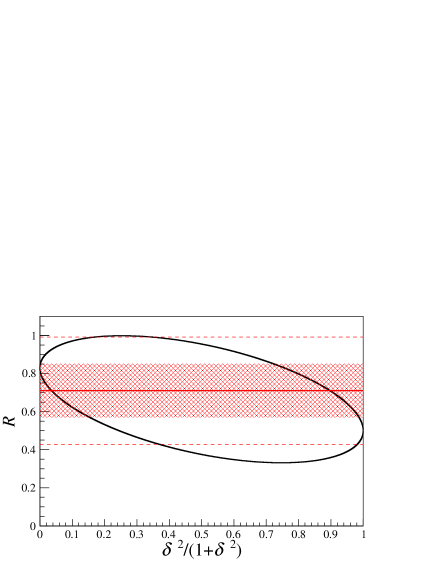
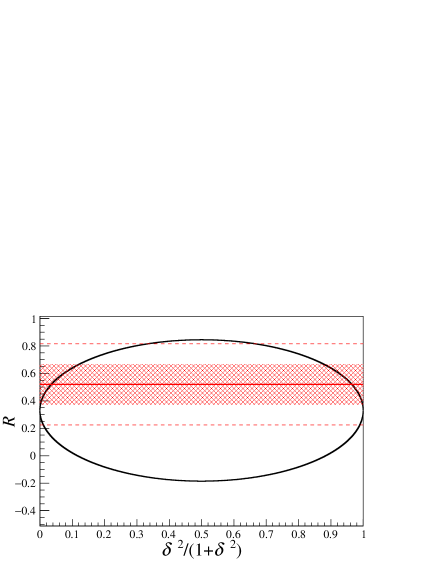
It is also possible to derive the mixing ratio of the transition of multiplicity (i.e., in this case, the mixing ratio of the M2 transition in the E1 transition) from this result. In the following, the mixing ratio, , was derived for the 2.4- and 3.2-MeV rays as a demonstration. The -values considering the transition are and for the 2.4- and 3.2-MeV rays from Eq. (19). Figure 13 displays the -value for the 2.4- and 3.2-MeV rays as a function of . The colored region represents the region, and the dotted lines represent the . The and for the 2.4- and 3.2-MeV transitions were obtained. Two solutions were produced; however, mixing M2 transitions is generally so small that the one with the smaller is described. Although significant mixing of the M2 transition was not observed because of the large uncertainty, the mixing ratio can be determined by measuring the circular polarization in ANNRI.
It is expected to determine the spin, , and the mixing of transitions by performing similar experiments on other nuclei and improving the accuracy in the future. We plan to apply this method to determine the spin of the final state of 139Lan, which is crucial for verifying the s-p mixed model.
6 Conclusions
Measurements of the circular polarization of rays emitted from neutron capture reactions provide valuable information for studying nuclear physics. The -ray polarimeter was developed as a -ray circular polarization measurement system installed in a highly intense pulsed neutron source. The analyzing power and magnetic hysteresis, used as performance indicators, were measured using a circularly polarized -ray beam at BL1U in the UVSOR facility. The analyzing power was obtained to be for the -MeV rays. It was confirmed that the current applied to the polarimeter was sufficiently saturated when it exceeded A.
Furthermore, as a demonstration of circular polarization measurement in the pulsed neutron source, the circular polarization of rays emitted from 32S(,)33S reactions with polarized neutrons was measured at ANNRI of the MLF in J-PARC. The analyzing power was found to be from the -MeV rays. The circular polarization of other rays normalized to this value was consistent with the theoretical calculations. It has been possible to measure the circular polarization of rays from neutron capture reactions in a pulsed neutron source for the first time. Various experiments in nuclear physics using circular polarization of neutron capture reactions are expected to be performed at ANNRI in the future.
Acknowledgements.
The authors would like to thank the staff of beamline 04, ANNRI, for the maintenance of the germanium detectors, and MLF and J-PARC for operating the accelerators and the neutron production target. The authors would also like to thank the staff of beamline 10, NOBORU, where the exploratory experiment was performed. The neutron experiments at the MLF of J-PARC were performed under the user program (Proposals No. 2021B0385, 2022A0230, 2022B0187, 2023A0129). The -ray experiments were performed at the BL1U of the UVSOR Synchrotron Facility with the approval of the Institute for Molecular Science (IMS), NINS (Proposals No.22-602 and 22-803). This work was supported by the Neutron Science Division of KEK as an S-type research project with program number 2018S12. This work was partially supported by JSPS KAKENHI Grant Nos. JP19K21047, JP20K04007, JP20K14495, and JP21K04950.References
- (1) L.C. Biedenharn, M.E. Rose, G.B. Arfken, Phys. Rev. 83, 683 (1951). DOI https://doi.org/10.1103/PhysRev.83.683
- (2) G.E. Mitchell, J.D. Bowman, S.I. Penttilä, E.I. Sharapov, Phys. Rep. 354, 157 (2001). DOI https://doi.org/10.1016/S0370-1573(01)00016-3
- (3) V.V. Flambaum, O.P. Sushkov, Nucl. Phys. A 435, 352 (1985). DOI https://doi.org/10.1016/0375-9474(85)90469-5
- (4) T. Okudaira, et al., Phys. Rev. C 97, 034622 (2018). DOI https://doi.org/10.1103/PhysRevC.97.034622
- (5) T. Yamamoto, et al., Phys. Rev. C 101, 064624 (2020). DOI https://doi.org/10.1103/PhysRevC.101.064624
- (6) T. Okudaira, et al., Phys. Rev. C 104, 014601 (2021). DOI https://link.aps.org/doi/10.1103/PhysRevC.104.014601
- (7) J. Koga, et al., Phys. Rev. C 105, 054615 (2022). DOI https://link.aps.org/doi/10.1103/PhysRevC.105.054615
- (8) S. Endo, et al., Phys. Rev. C 106, 064601 (2022). DOI 10.1103/PhysRevC.106.064601
- (9) T. Okudaira, et al., Phys. Rev. C 107, 054602 (2023). DOI 10.1103/PhysRevC.107.054602
- (10) G. Trumpy, Nucl. Phys. 2, 664 (1956). DOI https://doi.org/10.1016/0029-5582(56)90113-4
- (11) J. Vervier, Nucl. Phys. 26, 10 (1961). DOI https://doi.org/10.1016/0029-5582(61)90112-2
- (12) J. Kopecký, E. Warming, Nucl. Phys. A 127, 385 (1969). DOI https://doi.org/10.1016/0375-9474(69)90579-X
- (13) F. Djadali, J. Elchler, Nucl. Phys. A 165, 560 (1971). DOI https://doi.org/10.1016/0375-9474(71)90470-2
- (14) R. Vennink, W. Ratynski, J. Kopecky, Nucl. Phys. A 299, 429 (1978). DOI https://doi.org/10.1016/0375-9474(78)90381-0
- (15) A. Komives, A.K. Sint, M. Bowers, M. Snow, J. Res. Natl. Inst. Stand. Technol. 110, 221 (2005). DOI https://doi.org/10.6028/jres.110.028
- (16) M. Katoh, et al., J. Phys. Conf. Ser. 2687, 032005 (2024). DOI https://10.1088/1742-6596/2687/3/032005
- (17) R.B. Chesler, Nucl. Inst. Meth. 37, 185 (1965). DOI https://doi.org/10.1016/0029-554X(65)90362-9
- (18) H.A. Tolhoek, Rev. Mod. Phys. 28, 277 (1956). DOI https://doi.org/10.1103/RevModPhys.28.277
- (19) L. Murata Software Co. Femtet. https://www.muratasoftware.com (2023)
- (20) K. Aulenbacher, E. Chudakov, D. Gaskell, J. Grames, K. Paschke, Int. J. Mod. Phys. E 27, 1830004 (2018). DOI https://doi.org/10.1142/S0218301318300047
- (21) S. Takada, et al., JINST 13, P02018 (2018). DOI https://doi.org/10.1088/1748-0221/13/02/P02018
- (22) GEANT4. Geant4. https://geant4.web.cern.ch (2023)
- (23) Y. Taira, et al., Phys. Rev. A 107, 063503 (2023). DOI https://doi.org/10.1103/PhysRevA.107.063503
- (24) T. Kondo, et al., Nucl. Inst. Meth. A 659, 462 (2011). DOI https://doi.org/10.1016/j.nima.2011.08.035
- (25) M.W. Konijnenberg, et al., Phys. Lett. B 205, 215 (1988). DOI https://doi.org/10.1016/0370-2693(88)91652-8
- (26) T. Okudaira, et al., Nucl. Inst. Meth. A 977, 164301 (2020). DOI https://doi.org/10.1016/j.nima.2020.164301
- (27) L.W. Fagg, S.S. Hanna, Rev. Mod. Phys. 31, 711 (1959). DOI https://doi.org/10.1103/RevModPhys.31.711
- (28) K. Alder, B. Srech, A. Winther, Phys. Rev. 107, 728 (1957). DOI https://doi.org/10.1103/PhysRev.107.728
- (29) J. Chen, B. Singh, Nuclear Data Sheets 112, 1393 (2011). DOI https://doi.org/10.1016/j.nds.2011.04.003