Anisotropic magnetization dynamics in Fe5GeTe2: Role of critical fluctuations
Abstract
We analyze the magnetization dynamics and magnetic anisotropy in bulk single crystalline Fe5GeTe2, a van der Waals 2D ferromagnet, using broadband Ferromagnetic Resonance Spectroscopy. We find sizable anisotropy in the Lande g factor at room temperature which is attributed to anisotropic critical fluctuations and not spin-orbit interaction.
Introduction.— Fe5GeTe2 (F5GT) is a recently discovered vdW ferromagnet with a notably elevated Curie temperature of K, and gathered attention due to its potential application in the field of spintronics. In terms of universality class, F5GT lies somewhere between the 3D Heisenberg model and the 3D XY model Li et al. (2020). However, recent first principle study suggests a significant orbital contribution associated with non-equivalent iron sites in the magnetization of F5GT Joe et al. (2019) which apparently shows up in the study of its magnetization dynamics Alahmed et al. (2021). The contribution of spin orbit interaction can be comprehensively probed using the Ferromagnetic resonance spectra: 1) directly: by studying the angle dependence of the Lande’s g-factor; 2) indirectly: by studying the angle dependence of the magnetization ‘damping’ factor.
Despite the dominance of crystal field interaction over spin-orbit interaction for 3d ions like Fe2+ and Fe3+, there is a possibility that the orbital angular momentum may not be fully quenched in FGT due to the non-negligible spin-orbit interaction. This could in principle lead to an almost quenched ground state, with the g-factor deviating marginally from the spin-only value of 2. The deviation from 2 reflects the presence of mixed-in states. Thus an orbital contribution in the magnetization of F5GT is theoretically plausible as suggested by recent studies on angle dependence of g-factor Alahmed et al. (2021). However, one should be a little careful in jumping to a definite conclusion. Close to the critical temperature, in addition to the spin-orbit interaction, anisotropic critical fluctuations Nagata (1977); Nagata et al. (1972); Nagata and Tazuke (1972); Nagata et al. (1977) can also contribute to the experimental observation of the angle-dependent g-factor.
The magnetization ‘damping’ factor determines the stability and lifetime of magnetic excitation in a solid. It is deduced from the resonant line width in ferromagnetic-resonance (FMR) experiments Barman and Sinha (2018). The line-width of the FMR spectra is usually caused by intrinsic and extrinsic relaxation effects. The long-range fluctuations due to variation in sample parameters such as the internal fields, thickness, or orientation of crystals can lead to variation of local resonance fields resulting in frequency independent inhomogeneous line broadening of the FMR signal due to superposition of these local resonances. The short-range fluctuations due to two magnon scattering can be suppressed when the magnetization is oriented perpendicular to the sample plane. Extrinsic contributions to damping also arise due to eddy currents and the ‘field dragging effect’ between the magnetically hard and easy directions. If all extrinsic contributions are neglected, the Gilbert damping parameter is expected to scale as Li et al. (2019a), where is the density of states at the Fermi level , is the strength of the spin–orbit interaction and is the electron momentum scattering time. In general, it is assumed that the damping parameter is an isotropic scalar except for spin-orbit coupled systems where there is significant lattice or electronic structure anisotropy Seib et al. (2009); Gilmore et al. (2010a); Zhai et al. (2007); Kasatani and Nozaki (2015); Chen et al. (2018a); Li et al. (2019a); Thonig and Henk (2014); Miranda et al. (2021).
In this letter, we provide unambiguous evidence of magnetic anisotropy, originating from the interplay of anisotropic spin-spin interactions and enhanced magnetic fluctuations in ferromagnetic van der Waals single crystal Fe5GeTe2 at room temperature. The presence of anisotropic critical fluctuation induced magnetic anisotropy manifests in sizable polar angle dependent anisotropy of Lande’s g-factor, the dimensionless form of gyromagnetic ratio. We do not observe any intrinsic angular variation of the damping factor at room temperature, which further confirms that orbital magnetism has negligible role behind g-factor anisotropy in Fe5GeTe2.
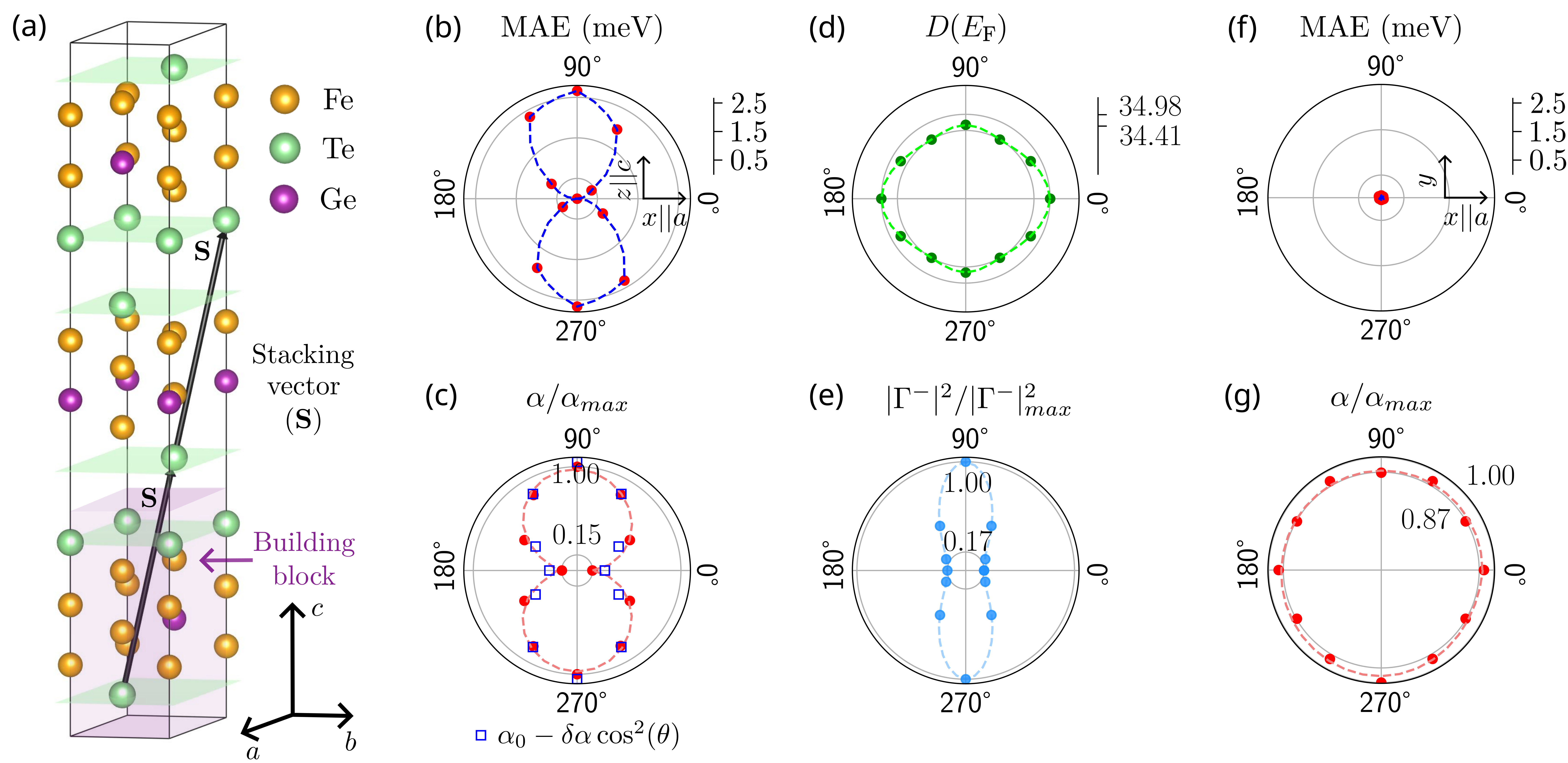
Ab initio calculations.— Bulk Fe5GeTe2 crystallizes in the non-centrosymmetric space group R3m (number 160) Stahl et al. (2018). The unit cell [shown in Fig. 1a] comprises of three blocks with a stacking vector , where are the three lattice parameters of the bulk. Inside a block, Fe and Ge layers are sandwiched between two planes of Te atoms (green planes in Fig. 1a). The two nearest blocks are connected with van der Walls interaction due to large distance ( 3.06 Å) between two consecutive Te planes. The Fe atoms inside each block has finite magnetization. The exchange couplings between Fe atoms inside a block or in between two blocks are ferromagnetic (FM) in nature. The FM F5GT is metallic with contributions of many bands at the Fermi energy, , as shown in Fig. 4b of SI, where the colinear spins are aligned along [100] crystal direction in presence of spin-orbit coupling (SOC). As the spins rotate the metallic Fermi surfaces also modify. The damping of magnetization dynamics depends on the variations in the Fermi surfaces. The change in the magnetization orientation induces a non-equilibrium population imbalance of itinerant electrons, which relaxes to the equilibrium distribution over a scattering timescale of Kamberský (1970, 1984); Korenman and Prange (1972); Kuneš and Kamberský (2002). The lagged excited states repopulate the empty equilibrium states by transferring angular momentum to the lattice and the damping arises Gilmore et al. (2010b); Kamberský (1976); Gilmore et al. (2007).
The matrix elements of the magnetization damping tensor are given by Miranda et al. (2021)
| (1) |
Here, and ( and ) represent the band (Cartesian coordinate) indices, is the band dispersion at momentum k for the -th band. In Eq. (1), with being the Fermi distribution function and , , and are the relaxation time, Landé g factor, magnetization and Planck’s constant, respectively. Here, captures the change in the band energy of the system on changing the direction of magnetization by a small amount. This change in band energy is primarily induced by the change in the spin-orbit coupling Hamiltonian of the system on changing the magnetization direction. For a colinear FM, assuming the local magnetization to be along the direction, the scalar is calculated by taking the average value, Miranda et al. (2021).
We present the variation of the calculated magnetic anisotropy energy (MAE) with polar angle (in the plane) in Fig. 1b. The corresponding damping constant (normalized with its maximum value - ) shows a strong anisotropy 1c in the plane, roughly following the MAE anisotropy. Our calculations indicate that is 6.67 times stronger along the z-axis than the x-axis (or any other axis in the plane). Interestingly, there is no anisotropy in either the MAE energy or in the magnetization damping term in the plane, as shown in Fig. 1f and g for different magnetization directions.
The variation in the MAE and the magnetization damping coefficient can arise from the magnetization dependence of the density of states and the interplay of spin-orbit coupling and the magnetization direction. To understand the mechanism of the large damping anisotropy of around 670%, we present the variation of DOS at the Fermi energy [] with magnetization in Fig. 1d. We find that remains almost constant and shows no change with the magnetization direction. Thus, the damping anisotropy is likely to arise from the SOC.
To probe the role of SOC in inducing the damping anisotropy further, we note that at low temperatures, we can approximate the damping constant using the average of / over the single particle states at . We have Li et al. (2019b); Fähnle et al. (2008); Kamberský (1970, 1976, 2007); Gilmore et al. (2007, 2010c) as
| (2) |
Here, Gilmore et al. (2007). It captures the change in band energy arising from the interplay of magnetization rotation and SOC. Mathematically, we have with and , are the Pauli matrices. is the spin-orbit part of the Hamiltonian. The momentum independent in Eq. (2) is the average of matrices over the states at Fermi energy Li et al. (2019b). It is given by . We calculate , and present its angular variation in Fig. 1e. Our results highlight that the SOC effect has a strong anisotropy of 590%, making it the most significant factor giving rise to the large calculated spin-damping anisotropy at zero temperature. In our calculations, F5GT’s intrinsic electronic properties give rise to its magnetic anisotropy energy and the giant Gilbert damping anisotropy. This is in contrast to the damping anisotropy caused by interfacial SOC in Fe—GeAs Chen et al. (2018b) disappears as the Fe layers’ thickness increases.
Experimental methods.— Single crystals of Fe5GeTe2 were prepared using chemical vapour transport method. The average dimension of the single crystals was close to mm. Energy-dispersive X-ray spectroscopy (EDS) was used to confirm stoichiometric ratio of the system. X-ray diffraction (XRD) measurement was carried out using a PANalytical X’Pert diffractometer on the bulk single crystals to confirm good crystallinity of the samples.
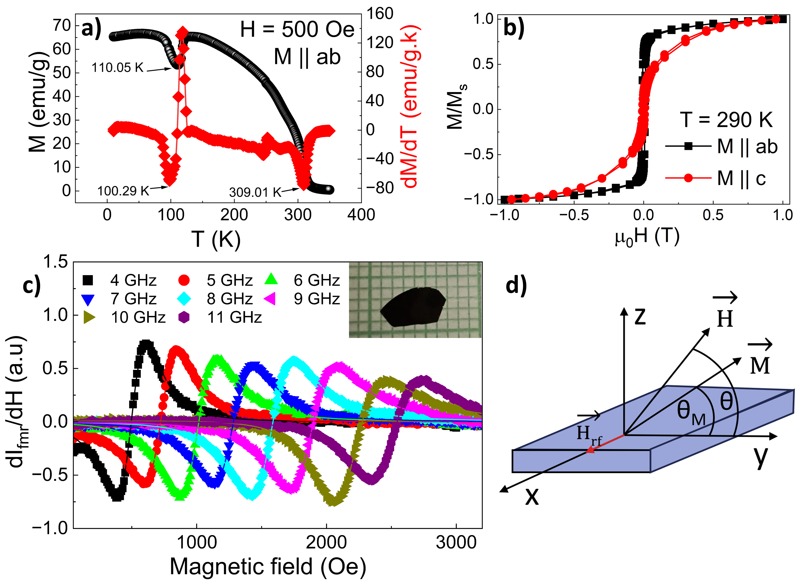
The temperature dependence of magnetization and the isothermal magnetization hysteresis measurement were carried out using a Quantum Design PPMS. Fig. 2a shows the field cooled (FC) temperature dependent in-plane (ab) magnetization. The Curie temperature was estimated from the derivative of the magnetization curve which turned out to be T K. A magnetic reorientation transition is also observed at low temperature. The magnetic hysteresis at K in the ab plane and along c axis (Fig. 2b) show clear easy in-plane anisotropy. It was also verified that there is no uniaxial anisotropy along the ab plane. The magnetization along ab plane is saturated at Oe while along the c axis the saturation field is nearabout 1 T.
We performed FMR measurement using PhaseFMR (NanoSc, Sweden), on the FGT single crystal in presence of MW field of different frequencies at room temperature. The sample was placed on a coplanar waveguide on which an external dc magnetic field was applied in various direction in the ab (in-plane) and along c axis (out-of-plane) in addition to a microwave field along the ab plane, as shown in Fig. 2d. The polar angle between the applied dc magnetic field and the ab plane is labeled as , while the azimuthal angle in the ab plane is labeled as . The range of microwave frequencies was kept between 8-15 GHz which ensured that the magnetization of the sample is fully saturated at FMR at all angles () measured.
Results and discussion.— A few representative spectra at different frequencies in the in-plane geometry are shown in Fig. 2c. After subtracting the offset and the linear contribution, the spectrum is fitted with the sum of the symmetric and anti-symmetric Lorentzian function given by,
| (3) |
where is the applied field, is the line-width, is the resonant field. and are the weight of the anti-symmetric and symmetric Lorentzian function, respectively. We obtain parameters such as and from the Lorentzian fit, at various MW frequencies , for further analysis.
For systems exhibiting significant out-of-plane hard axis anisotropy, while having no uniaxial ansiotropy in the easy plane, the free energy density of the magnetic configuration can be expressed as
| (4) |
here and represent the angles between the crystal ab-plane and the orientations of magnetization and magnetic field, respectively. Whereas, and denotes the azimuthal angles corresponding to magnetic field and magnetization vector respectively. denotes the effective magnetization of the system, which is linked to the saturation magnetization and the perpendicular anisotropy constant through the equation in CGS system.
Through energy minimization calculations, the Kittel equation can be derived, describing the relationship between the applied magnetic field and the microwave frequency .
| (5) |
where
| (6) |
and,
| (7) |
Here is the gyromagnetic ratio. The dimensionless form of is called Landé g-factor, given by , where and is reduced Planck constant and Bohr magneton, respectively.
The angles and follow the relation given by,
| (8) |
which shows if , i.e. the magnetic field is along the ab-plane, then is also . Thus for in-plane orientation of external DC magnetic field, Eq. 5 simplifies to
| (9) |
We obtained and Oe. The small deviation of the g-factor from may be attributed to an orbital contribution to the magnetization due to spin-orbit coupling Alahmed et al. (2021). We shall come back to this question later.
As discussed earlier, the line-width broadening can be described as arising from a combination of intrinsic contribution resulting from Gilbert damping and extrinsic contributions arising from sample imperfections and scattering phenomena. Usually, demonstrates a linear trend with variation in frequency and can be written as,
| (10) |
where is the Gilbert damping factor, is in-homogeneous line-width broadening. The quantity is frequently referred to as the dragging function, arising from the drag effect, i.e. misalignment between the magnetic field and the magnetization of the system, and is given by,
| (11) |
For in-plane configuration, and Eq. 11 reduces to
| (12) |
After fitting the in-plane FMR spectra with this equation, we determined and Oe for the in-plane configuration, which is independent of , suggesting the absence of uniaxial anisotropy in the ab plane.
Polar angle-dependent magnetization dynamics.— The ab-plane of the bulk single crystal was subjected to in-plane () and out-of-plane () rotations with respect to the external static magnetic field direction, at different fixed MW frequencies to investigate the orientation-dependent variation in magnetization dynamics.
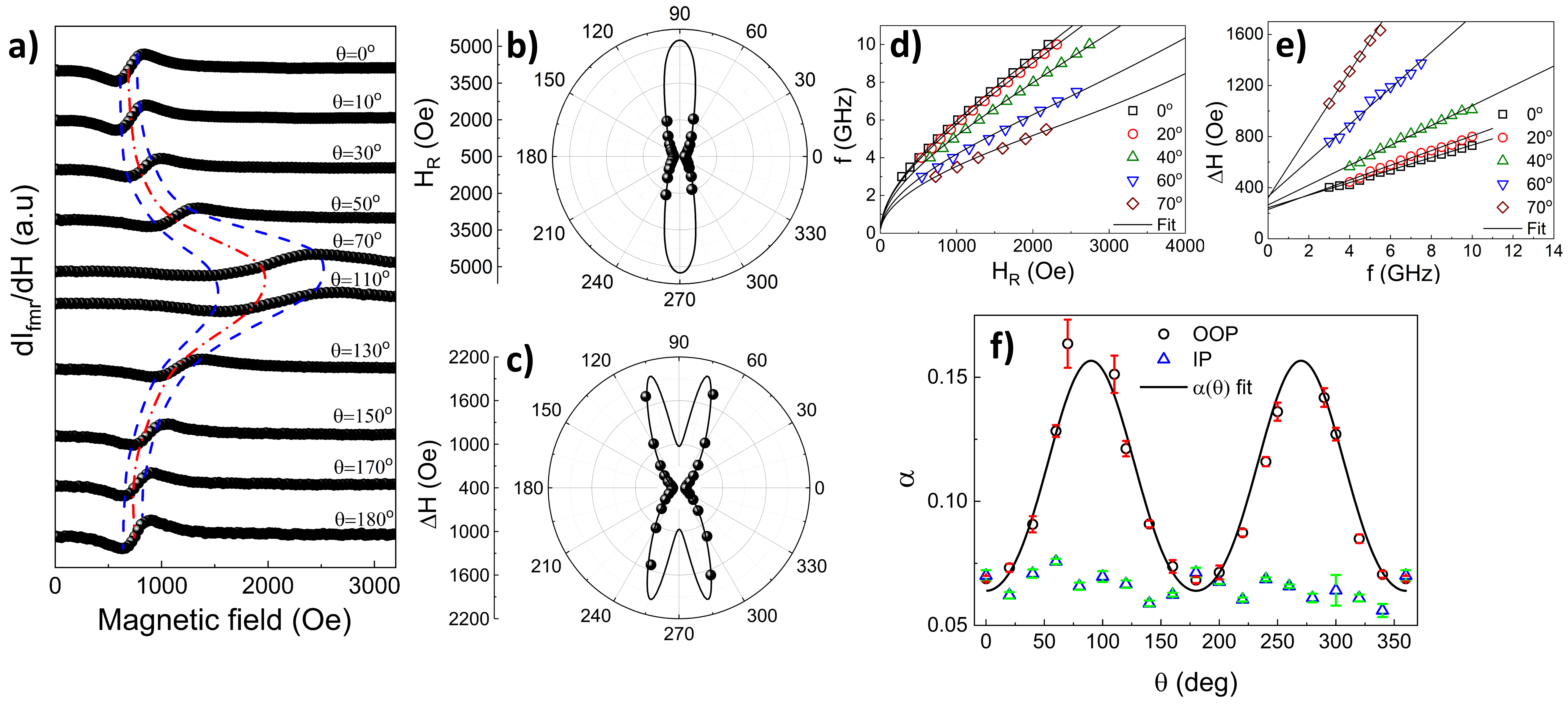
Although no uniaxial anisotropy is observed in in the ab plane, the plot of dependent resonant magnetic field indicates the presence of two-fold anisotropy in the direction. The easy plane aligns with the ab-plane, while the hard axis is oriented along the c-axis. The variation of the resonant magnetic field with polar angle can be accurately described by the model presented in Eq. 5, which demonstrates an excellent fit with the experimental data as shown in Figure 3b.
In order to investigate the anisotropic characteristics of the linewidth and Gilbert damping factor , we conducted an analysis of the microwave (MW) frequency dependence of the FMR spectra at different orientations of the external magnetic field along the direction. The frequency was varied from 3 to 11 GHz, while the angle between the crystal’s ab plane and the direction of the magnetic field was systematically varied in the range of to .
Gilbert damping parameter for in-plane orientations were determined by fitting the vs. data to Eq. 12 at different angles. To extract at various values, we prepare two sets of data: vs. at a fixed GHz and vs. at various values. Both datasets were fitted with Eq. 10 in order to determine the values corresponding to different orientations .
Although and is isotropic against rotation, there is clear two-fold anisotropy in with variation (Fig. 3c). Curiously, is found to show a two-fold anisotropy with the polar angle variation (Fig. 3f) with a maximum of almost 300 increase compared to the minimum damping at at room temperature. Such large variation in with variation in is not only rare but theoretically non-trivial as the anisotropy in does not necessarily guarantee anisotropy in . Usually, the dragging function is independent and maintains a constant value of 1. In such a scenario, Eq. 10 reduces to Eq. 12. However, the existence of anisotropy within a system, stemming from factors like demagnetizing field, perpendicular magnetic anisotropy (PMA), surface anisotropy, etc. can give rise to a dragging phenomenon as the magnetization vector either lags or leads the magnetic field orientation, resulting in a pronounced dependence of the dragging function itself. This phenomenon may generate an anisotropic , even if remains constant. Moreover, the angular dependency of two magnon scattering can also contribute to angular variation of .
Furthermore, our investigations reveal that the inhomogeneous linewidth broadening exhibits minimal out-of-plane anisotropy. Spin pumping contributions to the Gilbert damping are negligible for a bulk sample without any nonmagnetic metal capping layer. The spectacular angular variation of damping could not be attributed to the dominance of two-magnon scattering contribution which leads to high frequency nonlinear line-width softening. Two magnon scattering is largely suppressed in the out of plane configuration and there is no anisotropy of line width as a function of azimuth angle in the in-plane configuration.
The eddy current damping (in SI unit) is given by Li and Bailey (2016)
| (13) |
where is the vacuum permeability, Ms is the saturation magnetization and and are the thickness and resistivity, respectively, of the sample. Skin-depth of any metallic sample is given by For sample thickness higher than the skin-depth, the current density is localized primarily along the sample edge. Due to this localized distribution, the induced current is approximated to the first order as a current loop along the sample edge.
For a sample of skin depth , thickness t subjected to a static field applied along the ab-plane, the modified expression for eddy current damping takes the form
| (14) |
The empirical expression of dependent eddy current damping factor is then given by,
| (15) |
where is the effective length scale due to skin effect. Here, is the correction for the eddy current redistribution due to rotation of magnetization and is cone angle correction, where and are cone angles for and , respectively. The effective damping factor is given by, where is the intrinsic Gilbert damping factor.
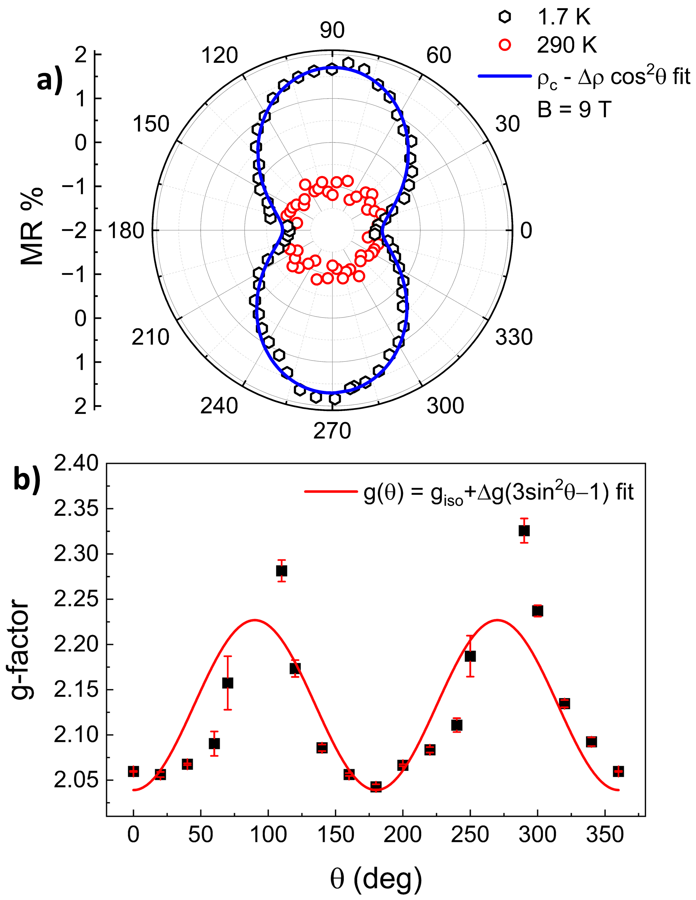
For Fe5GeTe2, system parameters are found to be: t T and . This gives skin-depth for our system to be . We take typical cone angle values of and . It is found that this analysis is immune to a moderate variation in these values. Keeping t and as free parameters, fitting (Fig. 3f) with the experimental data gives and which are quite close to experimentally found values, indicating that eddy current induced damping is mostly responsible for the observed anisotropy in Gilbert damping factor. Near room-temperature, spin-orbit coupling contribution is largely suppressed. This diminished effective spin-orbit coupling strength near room-temperature is also reflected in the weak polar angular dependency of magneto-resistance even in the presence of 9 T magnetic field as shown in Fig 4a.
Furthermore, by fitting Eq. 5 to the f vs. data taken at various polar angles , we determine the angular variation of the gyromagnetic ratio and the Landé g-factor. Fig. 4b depicts anisotropic out-of-plane g-factor as found in Fe5GeTe2 system. Beyond the spin-orbit interaction, anisotropic critical fluctuations, as demonstrated by Nagata et al. Nagata (1977); Nagata et al. (1972); Nagata and Tazuke (1972); Nagata et al. (1977), can also contribute to the experimental observation of the angle-dependent g-factor. With the magneto-resistance data demonstrating the negligible impact of spin-orbit contribution at room temperature, we can reasonably deduce that this critical phenomenon is the predominant mechanism behind the anisotropic behavior of the g-factor in F5GT, the experiment temperature ( 290 K) being close to its critical temperature ( 310 K).
The Nagata theory, as extended for the ferromagnetic state gives the expression Li et al. (2022) of the anisotropic g-factor as:
| (16) |
being isotropic component of the g-factor and is the g-shift amplitude due to anisotropic critical fluctuation. As can be seen from Fig. 4b, the extracted g-factor fits well with the angular dependence proposed by this theory. We get , which is slightly higher that the spin-only value of . This indicates towards some finite but weak orbital contribution to the magnetization of Fe5GeTe2 even at the room temperature. The g-shift amplitude for F5GT turns out to be , which gives g-shift along the c-axis , roughly similar to that of CGT () Li et al. (2022). This is reasonable as CGT and F5GT follows similar universality class of models. CGT fits into quasi-isotropic Heisenberg spin models Gong et al. (2017) while F5GT sits between the 3D Heisenberg model and the 3D XY model Li et al. (2020).
All points taken together, our findings strongly support the notion that the out-of-plane anisotropic linewidth broadening in FGT at room temperature arises primarily from the eddy current contribution. Although theoretical calculations support the intrinsic origin of anisotropy due to spin-orbit interaction at low temperature, it does not contribute to anisotropy of Gilbert damping factor at room-temperature, neither it plays any significant role behind g-factor anisotropy. We show that the intrinsic angular variation of g-factor primarily stems from enhanced anisotropic critical spin fluctuations, critical temperature of F5GT being close to room temperature. Our findings offer new insights into the fundamental physics of magnetization dynamics in van der Waals magnets and open up exciting possibilities for future research in spintronics.
Acknowledgements.— SM and AKA acknowledge Department of Science and Technology, India, DST Nanomission, for financial support. AB thanks PMRF for financial support.
References
- Li et al. (2020) Z. Li, W. Xia, H. Su, Z. Yu, Y. Fu, L. Chen, X. Wang, N. Yu, Z. Zou, and Y. Guo, Scientific Reports 10, 15345 (2020), ISSN 2045-2322, URL https://doi.org/10.1038/s41598-020-72203-3.
- Joe et al. (2019) M. Joe, U. Yang, and C. Lee, Nano Materials Science 1, 299 (2019), ISSN 2589-9651, special Issue on two-dimensional nanomaterials, URL https://www.sciencedirect.com/science/article/pii/S2589965119300637.
- Alahmed et al. (2021) L. Alahmed, B. Nepal, J. Macy, W. Zheng, B. Casas, A. Sapkota, N. Jones, A. R. Mazza, M. Brahlek, W. Jin, et al., 2D Materials 8, 045030 (2021), URL https://dx.doi.org/10.1088/2053-1583/ac2028.
- Nagata (1977) K. Nagata, Physica B+C 86-88, 1283 (1977), ISSN 0378-4363, URL https://www.sciencedirect.com/science/article/pii/0378436377908828.
- Nagata et al. (1972) K. Nagata, Y. Tazuke, and K. Tsushima, Journal of the Physical Society of Japan 32, 1486 (1972), eprint https://doi.org/10.1143/JPSJ.32.1486, URL https://doi.org/10.1143/JPSJ.32.1486.
- Nagata and Tazuke (1972) K. Nagata and Y. Tazuke, Journal of the Physical Society of Japan 32, 337 (1972), eprint https://doi.org/10.1143/JPSJ.32.337, URL https://doi.org/10.1143/JPSJ.32.337.
- Nagata et al. (1977) K. Nagata, I. Yamamoto, H. Takano, and Y. Yokozawa, Journal of the Physical Society of Japan 43, 857 (1977), eprint https://doi.org/10.1143/JPSJ.43.857, URL https://doi.org/10.1143/JPSJ.43.857.
- Barman and Sinha (2018) A. Barman and J. Sinha, Springer (2018).
- Li et al. (2019a) Y. Li, F. Zeng, S. S.-L. Zhang, H. Shin, H. Saglam, V. Karakas, O. Ozatay, J. E. Pearson, O. G. Heinonen, Y. Wu, et al., Phys. Rev. Lett. 122, 117203 (2019a), URL https://link.aps.org/doi/10.1103/PhysRevLett.122.117203.
- Seib et al. (2009) J. Seib, D. Steiauf, and M. Fähnle, Phys. Rev. B 79, 092418 (2009), URL https://link.aps.org/doi/10.1103/PhysRevB.79.092418.
- Gilmore et al. (2010a) K. Gilmore, M. D. Stiles, J. Seib, D. Steiauf, and M. Fähnle, Phys. Rev. B 81, 174414 (2010a), URL https://link.aps.org/doi/10.1103/PhysRevB.81.174414.
- Zhai et al. (2007) Y. Zhai, C. Ni, Y. Xu, Y. B. Xu, J. Wu, H. X. Lu, and H. R. Zhai, Journal of Applied Physics 101, 09D120 (2007), ISSN 0021-8979, eprint https://pubs.aip.org/aip/jap/article-pdf/doi/10.1063/1.2712297/14059017/09d120_1_online.pdf, URL https://doi.org/10.1063/1.2712297.
- Kasatani and Nozaki (2015) Y. Kasatani and Y. Nozaki, Journal of the Magnetics Society of Japan 39, 221 (2015).
- Chen et al. (2018a) L. Chen, S. Mankovsky, S. Wimmer, M. A. W. Schoen, H. S. Körner, M. Kronseder, D. Schuh, D. Bougeard, H. Ebert, D. Weiss, et al., Nature Physics 14, 490 (2018a), ISSN 1745-2481, URL https://doi.org/10.1038/s41567-018-0053-8.
- Thonig and Henk (2014) D. Thonig and J. Henk, New Journal of Physics 16, 013032 (2014), URL https://dx.doi.org/10.1088/1367-2630/16/1/013032.
- Miranda et al. (2021) I. P. Miranda, A. B. Klautau, A. Bergman, D. Thonig, H. M. Petrilli, and O. Eriksson, Phys. Rev. B 103, L220405 (2021), URL https://link.aps.org/doi/10.1103/PhysRevB.103.L220405.
- Stahl et al. (2018) J. Stahl, E. Shlaen, and D. Johrendt, Zeitschrift für anorganische und allgemeine Chemie 644, 1923 (2018), eprint https://onlinelibrary.wiley.com/doi/pdf/10.1002/zaac.201800456, URL https://onlinelibrary.wiley.com/doi/abs/10.1002/zaac.201800456.
- Kamberský (1970) V. Kamberský, Canadian Journal of Physics 48, 2906 (1970), URL https://doi.org/10.1139/p70-361.
- Kamberský (1984) V. Kamberský, Czechoslovak Journal of Physics B 34, 1111 (1984), ISSN 1572-9486, URL https://doi.org/10.1007/BF01590106.
- Korenman and Prange (1972) V. Korenman and R. E. Prange, Phys. Rev. B 6, 2769 (1972), URL https://link.aps.org/doi/10.1103/PhysRevB.6.2769.
- Kuneš and Kamberský (2002) J. Kuneš and V. Kamberský, Phys. Rev. B 65, 212411 (2002), URL https://link.aps.org/doi/10.1103/PhysRevB.65.212411.
- Gilmore et al. (2010b) K. Gilmore, M. D. Stiles, J. Seib, D. Steiauf, and M. Fähnle, Phys. Rev. B 81, 174414 (2010b), URL https://link.aps.org/doi/10.1103/PhysRevB.81.174414.
- Kamberský (1976) V. Kamberský, Czechoslovak Journal of Physics B 26, 1366 (1976), ISSN 1572-9486, URL https://doi.org/10.1007/BF01587621.
- Gilmore et al. (2007) K. Gilmore, Y. U. Idzerda, and M. D. Stiles, Phys. Rev. Lett. 99, 027204 (2007), URL https://link.aps.org/doi/10.1103/PhysRevLett.99.027204.
- Li et al. (2019b) Y. Li, F. Zeng, S. S.-L. Zhang, H. Shin, H. Saglam, V. Karakas, O. Ozatay, J. E. Pearson, O. G. Heinonen, Y. Wu, et al., Phys. Rev. Lett. 122, 117203 (2019b), URL https://link.aps.org/doi/10.1103/PhysRevLett.122.117203.
- Fähnle et al. (2008) M. Fähnle, D. Steiauf, and J. Seib, Journal of Physics D: Applied Physics 41, 164014 (2008), URL https://dx.doi.org/10.1088/0022-3727/41/16/164014.
- Kamberský (2007) V. Kamberský, Phys. Rev. B 76, 134416 (2007), URL https://link.aps.org/doi/10.1103/PhysRevB.76.134416.
- Gilmore et al. (2010c) K. Gilmore, M. D. Stiles, J. Seib, D. Steiauf, and M. Fähnle, Phys. Rev. B 81, 174414 (2010c), URL https://link.aps.org/doi/10.1103/PhysRevB.81.174414.
- Chen et al. (2018b) L. Chen, S. Mankovsky, S. Wimmer, M. A. W. Schoen, H. S. Körner, M. Kronseder, D. Schuh, D. Bougeard, H. Ebert, D. Weiss, et al., Nature Physics 14, 490 (2018b), ISSN 1745-2481, URL https://doi.org/10.1038/s41567-018-0053-8.
- Li and Bailey (2016) Y. Li and W. E. Bailey, Phys. Rev. Lett. 116, 117602 (2016), URL https://link.aps.org/doi/10.1103/PhysRevLett.116.117602.
- Li et al. (2022) Z. Li, D.-H. Xu, X. Li, H.-J. Liao, X. Xi, Y.-C. Yu, and W. Wang, Phys. Rev. B 106, 054427 (2022), URL https://link.aps.org/doi/10.1103/PhysRevB.106.054427.
- Gong et al. (2017) C. Gong, L. Li, Z. Li, H. Ji, A. Stern, Y. Xia, T. Cao, W. Bao, C. Wang, Y. Wang, et al., Nature 546, 265 (2017), ISSN 1476-4687, URL https://doi.org/10.1038/nature22060.