Impact of E-plane Misalignment on THz Diagonal Horn Antennas
Abstract
A key challenge in developing terahertz front-ends is achieving high coupling efficiency between the waveguide feed horn and the optical beam. In this paper, we have quantified the alignment requirements for the widely used E-plane split diagonal horn antenna through theoretical analysis, electromagnetic simulation, and experimental validation within the 325-500 GHz frequency range. The results from our analytical models, simulations, and measurements are consistent and shows good agreement. They reveal that even minor geometric asymmetries can cause significant increases in fractional power radiated to the cross-polar component due to amplitude and phase imbalances in the TE and TE modes. Furthermore, a misalignment of approximately 8% of the wavelength was observed to result in a 3-dB degradation in the optical coupling to a Gaussian beam (Gaussicity) in middle of the waveguide band. These findings highlight the critical importance of precise alignment and feed horn machining for the successful implementation of terahertz front-end systems.
Index Terms:
Antenna measurements, Aperture antennas, Horn antennas, Near-field measurements, Optical coupling, Sensitivity, Submillimeter wave propagation, Tolerance analysis.I Introduction
Feed horns [1] play a pivotal role in various terahertz quasi-optical applications [2] such as remote sensing [3, 4], imaging [5], material characterization [6], and spectroscopy [7]. These applications often use horns integrated with detectors to maximize the signal coupling to non-linear elements like diodes,[8, 9] or to radiate to free-space [10]. For astronomical receivers, high sensitivity and low cross polarization are critical, which makes corrugated feed horns an ideal candidate [11]. Electroforming has effectively produced corrugated horns with high Gaussicity (98%), but achieving uniform /4 corrugations and coating at sub-millimeter wavelengths is challenging and expensive. Alternative horn profiles, such as Pickett-Potter horns [12], conical horns [13], and smooth-walled spline horns [14], offer easier fabrication compared to electroforming. However, these horns are fed by circular waveguides, which require circular-to-rectangular waveguide transitions for circuit integration. Therefore, the classical diagonal horn is widely utilized among feed horns due to its simplified manufacturing process and seamless integration with rectangular waveguides. Notably, it has symmetrical E- and H-planes, suitable for both circular and linear polarization.
First introduced by Li in 1952 [15], diagonal horns feature a square aperture fed by a rectangular waveguide, with two transition sections converting the transverse-electric TE10 mode to TE11 in a circular waveguide and then to a diagonally polarized wave in the square waveguide - a superposition of two TE10 and TE01 waveguide modes. Subsequently, Love experimentally verified its radiation pattern and coined the term ’Diagonal horn’ [16]. Later, Johansson and Whyborn showed that the intermediate circular section could be omitted and proposed E-plane split-block realization for submillimeter wavelengths [17]. However, fabricating these components at high frequencies (1 THz) with micron-level precision presents significant challenges. The performance of diagonal horns depends on the phase and amplitude balance between the TE10 and TE01 modes. Any asymmetry, such as E-plane misalignment, can lead to mode imbalance, increasing cross polarization levels, and result in an elliptically polarised beam. The influence of mode amplitude imbalance was discussed by Withington and Murphy in [18], but the role of a phase between the modes has yet to be reported in the literature. Slight differences in propagation constants will cause a significant phase difference at the antenna aperture. Previous studies have documented similar issues; Kerr et al. noticed degradation in isolation for ortho-mode transducers (OMT) [19] and Ellison et al. observed discrepancies in the radiation pattern of a 3.5-THz quantum-cascade laser (QCL) integrated with dual diagonal feed horns due to fabrication imperfections and misalignment [10]. Montofre et al., [20] noticed unbalanced cross polarization levels in the D-plane and concluded that this is the effect of asymmetry between the blocks. Jayasankar et al. also reported higher conversion losses in a 3.5-THz harmonic mixer with a diagonal horn in a WM64 waveguide and attributed it to high loss in the RF chain [21].
In this paper, we study the performance degradation of THz diagonal horn antennas due to E-plane misalignment since it is the most common error arising from machining and alignment tolerances. The diagonal horn is a scaled version of the 4.7-THz antenna presented in [22] and the experiment is conducted at the WM570 frequency band to precisely control misalignment and to have a reliable antenna characterization. The rest of the paper is organized as follows: in section II, we have proposed an analytical model to compute the phase and amplitude imbalance caused by E-plane asymmetry in diagonal horns. We present the analytical results on the impact of misalignment on cross polarization loss at three frequencies, 1.3, 1.5, and 1.8, along with electromagnetic (EM) simulations. Following this, we present the mechanical design that allows intentional misalignment and machining of the WM570 diagonal horn. In section III, we present the near-field measurement setup and experimental characterization of the horn. We compare three alignment scenarios, a) perfectly aligned, b) misaligned by 22 m and c) misaligned by 40 m. Finally, we conclude by summarizing our findings and proposing an alternative solution to address this issue.
II Method
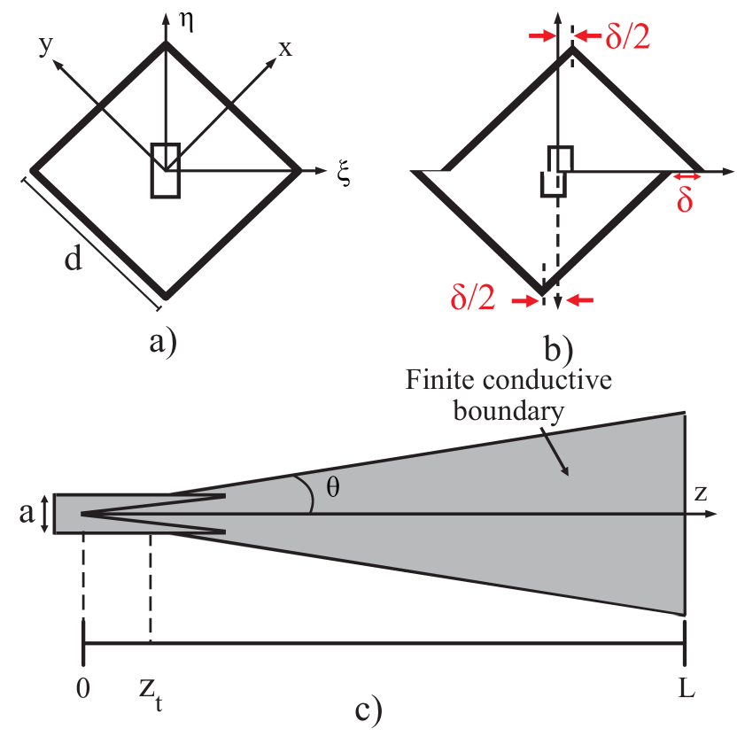
A standard WM570 diagonal horn (without the intermediate circular transition) was designed as described by Johansson and Whyborn [17], see Fig. 1. A square aperture with the side, mm, length mm, and corresponding flare angle tan were used, which results in a nominal antenna gain of circa 23 dBi. The feed is a standard rectangular waveguide (a b) of dimension 570 285 m2. To experimentally study the effect of E-plane misalignment , guide structures were machined in a split block to allow for alignment and intentional misalignments. This section describes the theory, EM simulations, mechanical design, machining and near-field characterization for analyzing the impact of E-plane misalignment.
II-A Theoretical analysis
The aperture field distribution of a diagonal horn antenna consists of an in-phase superposition of two orthogonal TE modes [17], TE10 and TE01,
| (1a) | |||
| (1b) | |||
where is the free space wavelength and is the spherical phase front [23]. When the split blocks are aligned as shown in Fig. 1a, the modes have phase and amplitude balance and exhibit the same propagation constant, , which is not valid for the misaligned and distorted cross-section shown in Fig. 1b. However, when the split blocks are slightly misaligned, the original square cross-section of the horn can be replaced with a rectangular shape, where one side of the cross-section becomes effectively narrower and the other broader . As a result, the two corresponding TE modes will have different propagation constants (, ) and wave impedances, creating a phase shift and amplitude imbalance along the length of the diagonal horn. In general, the imbalance between the two modes at the aperture can be expressed as
| (2) |
where is power balance factor proposed by Withington and Murphy [18], and is the total phase difference at the aperture. For a modest flare angle , neglecting reflections and losses, the total phase difference can be obtained as the sum of propagating infinitesimal waveguide sections dz.
| (3) |
where is the length of the horn, is the assumed starting point of the horn (throat), and c is the corresponding cross-section width at the throat. Note that the wavenumber of each mode, , changes with the position along the diagonal horn corrected with the misalignment . The integral can be solved using analytical methods, leading to a lengthy expression. However, a first-order approximation can be found by introducing the parameter, , and reorganizing Eq. (II-A) as:
| (4) |
Hence, the phase imbalance depends mainly on the flare angle, frequency, and the cross-section at the throat. For a large aperture , the phase imbalance can be further approximated as . Note that is a model fitting parameter representing the effective width of the throat cross-section.
Next, the amplitude or power imbalance results from uneven excitation of the two modes in the transition between the rectangular waveguide and the diagonal horn. For simplicity, we assume that the power imbalance only depends on the ratio of mode impedances at the throat. Using the power-voltage characteristic impedance definition (wave impedance scaled with waveguide height and width) [24, 25], the power balance, , can be estimated as:
| (5) |
Together with the aperture field, given in Eq.1a), the analytical model (4-5) provides insights and can be used to predict imbalance in phase and amplitude between the two modes, thereby allowing the calculation of the distorted aperture field for small misalignments (). The analytical model was validated with electromagnetic simulations of cross polarization coupling loss :
| (6) |
where and are the radiated copolar and cross polar power, respectively. For a perfectly aligned antenna, 9.5% of the total power is radiated into the cross polarized component as shown in Fig. 3 and it agrees with the theoretical prediction in [18, 17]. A throat cross-section width () between 0.7-0.8 resulted in a good agreement with full EM simulations.
II-B EM simulation
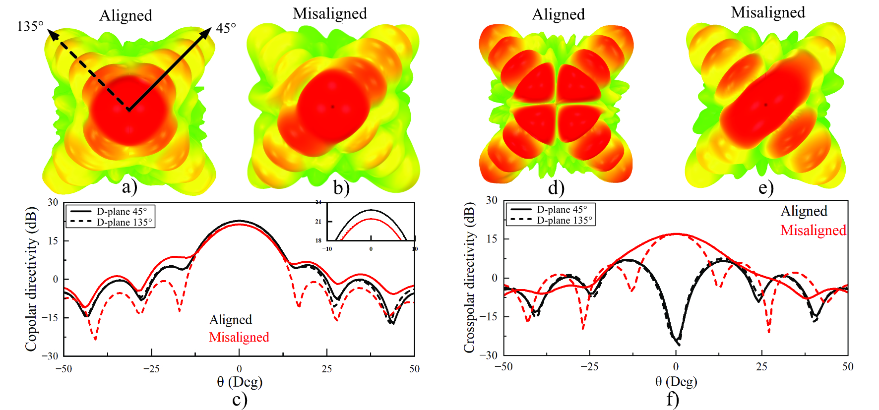
Fig. 1 shows the 3D-EM model of the diagonal horn. The EM simulations were carried out using a commercial finite-element method-based solver. A finite conductive boundary (aluminum) with electrical conductivity S/m was assigned to the antenna and waveguide walls. A radiation boundary box was placed at the end of the horn to obtain the far-field responses. The side with the horn aperture was assigned a finite conductive boundary, and the rest of the faces were assigned radiation boundaries as mentioned in [26]. Two-fold symmetry can significantly reduce the computational time for the perfectly aligned case. However, symmetrical boundary conditions are inapplicable for misaligned configurations, necessitating the simulation of the entire horn and thus increasing the computational time. Simulated directivity is about 23 dB and 3-dB E-plane half beam width (HPBW) is 13 degrees 470 GHz. Fig. 2a-b,d-e shows the simulated far-field radiation pattern of co and cross polar component of the diagonal horn at 470 GHz, respectively, for both aligned and misaligned antenna. Fig. 2c,f shows the D-plane cuts at and 135∘. In Fig. 2f, we see a null in the cross polar component at boresight as expected for the aligned case [17, 27] and when misaligned, shows an increased cross polar component at the boresight. Likewise, the copolar directivity also reduces by 1.5 dB when misaligned, as highlighted in the inset of Fig. 2c.
II-C Mechanical design
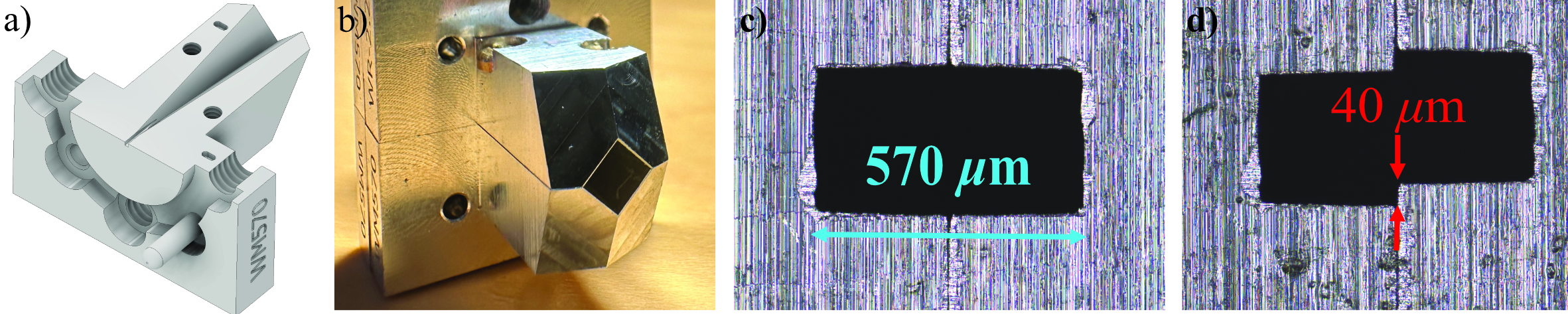
Fig. 4a shows the CAD model of the 470-GHz diagonal horn antenna integrated with a WM570 rectangular waveguide in an E-plane split-block housing. It has a waveguide flange based on UG-387 specification [28]. The length of the access waveguide to the horn was designed as short as possible to minimize attenuation. A 45∘ chamfer was implemented to redirect the reflected signal away from the optical axis.
The top split block has trenches along the edge of the waveguide and horn to ensure a tight fit between the blocks while assembling. To facilitate accurate alignment, two rectangular guide structures were incorporated onto the top surface of the split blocks. The bottom block features guide holes measuring 1045 510 m2, while the top block employs pins sized at 1000 500 m2. The intentional allowance in tolerance permits controlled sliding of the blocks, thus enabling effortless alignment and misalignment of the split blocks. Micrographs of two extreme cases are shown in Fig. 4c-d. The misalignment was measured using a metrology microscope with 1 m accuracy. Using guide structures offered advantages over traditional alignment methods, such as dowel pins, by minimizing rotational misalignments.
II-D Machining
The diagonal horn was machined from a single block of aluminum (Al 6082) alloys using a CNC machine (KERN Micro HD) with micrometer precision. First, planarization of the top surface was carried out using an end mill of 250 m-diameter. After machining the UG387 flange, the diagonal horn’s aperture was machined using a 45∘ chamfer mill with a top radius of 5 m, which resulted in a fillet with the same radius as the tool. Following that, a rectangular waveguide was machined using a 200-m tungsten end mill with sharp corners.
Removal of burrs along the edge of the waveguide is crucial since it could get folded into the waveguide cavity when the split-block halves are assembled. In addition, minor machining artifacts, especially at the horn’s throat, were removed to avoid any reflections affecting the antenna’s performance. After deburring, blocks were cleaned in an ultrasonic bath with acetone and isopropanol. The diagonal horn antenna machined in the E-plane split-block is shown in Fig. 4b. The cross-section of the WM570 waveguide aperture for the aligned and misaligned cases is shown in Fig. 4c-d.
II-E Measurement setup
Fig. 5 shows the near-field antenna measurement setup consisting of Keysight Vector Network Analyzer (VNA) N5242B and WM570 VDI frequency extenders. The antenna under test (AUT) is connected to the left with extender 1, and the WM570 open-ended rectangular waveguide was connected to the right with extender 2, which was mounted on a motorized linear XY stage with a step resolution of 2.5 m. Input signals from direct digital synthesizers (DDS) in the VNA were fed to the cascaded Schottky multiplier chain in the frequency extenders to generate output signals in the range of .
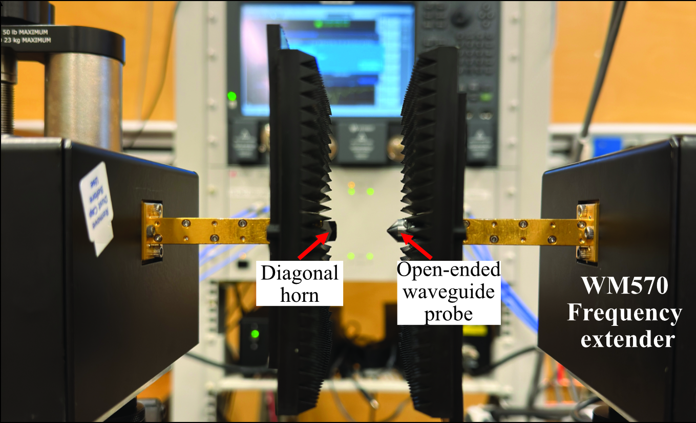
The amplitude and phase distribution of the diagonal horn antenna was measured at a distance of approximately from the horn aperture. The separation distance is a trade-off; while reducing the distance gives a smaller required scan area, care has to be taken to reduce the standing waves and evanescent fields [29]. A raster pattern was implemented to scan the rectangular x-y grid of size 22 22 mm2 with uniform spacing set to 500 GHz. The setup was mounted on a vibration-free optical test bench from Thor Labs; absorbers were used to reduce the free-space standing waves in the optical axis, and the bench was layered with Eccosorb AN-73.
III Results
First, the input return loss of the aligned horn antenna and WM570 open-ended waveguide probe was measured. Two-port short-offset short-load-thru (SOLT) calibration was carried out, and the IF bandwidth was set to 300 Hz. Input return loss of both horn and the waveguide probe is better than 20 dB throughout the whole band from as shown in Fig. 6. For comparison, simulation results of the diagonal horn are also included, which agrees well.
The probe was moved at a low speed for near-field scanning to avoid smearing effects. At the same time, measurement scan time was kept as short as possible with fewer frequency points. All measurements were performed in controlled conditions to reduce the implications of rapid temperature variations on phase drifts and ensure linear temperature drift. The port cables for extender 1 with AUT are stationary. However, cable movement in Extender 2 while scanning is unavoidable. So, a reference measurement was recorded at the boresight of the AUT after scanning each row, which was later used to make linear compensation of phase drift. An average magnitude drift of about 0.01 dB and phase drift of 10 degrees were recorded during the complete scan. The probe was aligned to the boresight of the AUT by employing a phase-detection scheme that finds the local phase minima of S21. The magnitude and phase of the tangential electric field components of the antenna were measured, and standard near-field to far-field transformation technique (NF/FF) [30, 31] was employed to compute the far-field radiation pattern of the antenna. For cross polar measurements, a 90∘ WM570 VDI waveguide twist was used.
Three cases were studied in detail: i) perfectly aligned, ii) misaligned by (22 m), and iii) misaligned by (40 m) where is the free space wavelength at 470 GHz. The directivity of the perfectly aligned diagonal antenna is measured at 22.8 dB, see Fig.7a, which is in good agreement with the simulation, see Fig. 2. The far-field cuts of an aligned diagonal horn antenna in E ( = 0∘) and H ( = 90∘) are shown in Fig. 8. As expected, the E- and H-planes are symmetrical, with equal beam widths and high sidelobe levels in the D-plane.
The far-field radiation pattern of aligned and misaligned antennas is shown in Fig. 7. When misaligned by 40 m, the copolar directivity reduces by 1.5 dB at 470 GHz as shown in Fig. 7a-c. The mode imbalance due to the E-plane misalignment results in a central cross-polarized lobe [18]. Discrepancies in measuring the sidelobe levels are due to the short planar scanning range, which restricts the validity to a limited angular span [32].
IV Discussion
The optical coupling to a Gaussian beam (Gaussicity) is an important parameter for quasi-optical system design, and it can be calculated from aperture E-fields as shown below [33],
| (7) |
where is the first-order Gaussian beam function.Fig. 9 shows the estimated performance degradation of the diagonal horn antenna due to E-plane misalignment along with the analytical model described earlier in Section II. The beam waist was kept constant as 0.86 [17] and note that the analytical model is valid only for small misalignment (). Evidently, Gaussicity follows the same trend as the cross polarization loss in Fig. 3 and is more sensitive when operating close to the cut-off frequency of the waveguide feed. From this, we can observe 3-dB degradation in Gaussicity at 8% misalignment relative to the wavelength when operating in the middle of the waveguide band. The degradation is even more severe in the low-frequency part of the waveguide band due to a larger dispersion (), resulting in a larger imbalance between the two modes. Hence, operating in the upper part of the waveguide band and using a larger flare angle, , will reduce the influence of E-plane misalignment. Hence, there will be a trade-off between flare angle for optimum gain and robustness against fabrication and assembly tolerances. A possible solution at very short wavelengths is to use a standard pyramidal horn, which is more or less immune to E-plane misalignment, thanks to the ’single’ mode (TE10) operation. Alternatively, use a horn with a throat that expands fast, such as the smooth-walled spline-profile diagonal horn [34], or similar conical spline-horns [35, 14].
V Conclusion
We have conducted a comprehensive study on the performance degradation of THz diagonal horn antennas due to misalignment in the E-plane. The alignment requirements have been quantified through a combination of theoretical analysis, EM simulations, and near-field antenna pattern measurements in the 325-500 GHz frequency range. The finite-element modeling matched very well with the proposed analytical model and experimental results, indicating that misalignment causes amplitude and phase imbalance in the TE01 and TE10 modes leading to high cross polarization loss. Particularly, when operating close to the cut-off frequency, , of the waveguide feed, the diagonal horn is severely impacted by misalignment. These results offer valuable practical design guidelines that are critical, especially beyond 3 THz. For future work, tolerance analysis work can be extended by addressing other critical horn parameters and comparing with other type of common terahertz horns..
Acknowledgement
The authors would like to thank Mats Myremark for the high-precision machining of the diagonal horn antenna. The authors would also like to acknowledge the Kollberg Laboratory and thank Helena Rodilla and Patrik Blomberg for proofreading the manuscript.
References
- [1] L. J. Chu and W. L. Barrow, “Electromagnetic horn design,” Transactions of the American Institute of Electrical Engineers, vol. 58, no. 7, pp. 333–338, 1939, DOI: 10.1109/T-AIEE.1939.5057968.
- [2] P. Goldsmith, “Quasi-optical techniques,” Proceedings of the IEEE, vol. 80, no. 11, pp. 1729–1747, 1992.
- [3] J. Treuttel, L. Gatilova, S. Caroopen, A. Feret, G. Gay, T. Vacelet, J. Valentin, Y. Jin, A. Cavanna, K. F. Jacob, S. Mignoni, V. Lavignolle, J.-M. Krieg, C. Goldstein, F. Courtade, C. Larigauderie, A. Ravanbakhsh, J.-P. Garcia, A. E. Maestrini, and P. Hartogh, “1200 GHz High Spectral Resolution Receiver Front-End of Submillimeter Wave Instrument for JUpiter ICy Moon Explorer: Part I - RF Performance Optimization for Cryogenic Operation,” IEEE Transactions on Terahertz Science and Technology, vol. 13, no. 4, pp. 324–336, 2023, DOI: 10.1109/TTHZ.2023.3263623.
- [4] A. Hammar, P. Sobis, V. Drakinskiy, A. Emrich, N. Wadefalk, J. Schleeh, and J. Stake, “Low noise 874 GHz receivers for the International Submillimetre Airborne Radiometer (ISMAR),” Review of Scientific Instruments, vol. 89, no. 5, May 2018, DOI: 10.1063/1.5017583.
- [5] S. Sung, S. Selvin, N. Bajwa, S. Chantra, B. Nowroozi, J. Garritano, J. Goell, A. D. Li, S. X. Deng, E. R. Brown, W. S. Grundfest, and Z. D. Taylor, “THz Imaging System for in vivo Human Cornea,” IEEE Transactions on Terahertz Science and Technology, vol. 8, no. 1, pp. 27–37, 2018, DOI: 10.1109/TTHZ.2017.2775445.
- [6] M. Mrnka, R. Appleby, and E. Saenz, “Accurate s-parameter modeling and material characterization in quasi-optical systems,” IEEE Transactions on Terahertz Science and Technology, vol. 12, no. 2, pp. 199–210, 2022, DOI: 10.1109/TTHZ.2021.3140201.
- [7] R. Voigt, M. Wienold, D. Jayasankar, V. Drakinskiy, J. Stake, P. Sobis, L. Schrottke, X. Lü, H. T. Grahn, and H.-W. Hübers, “Frequency stabilization of a terahertz quantum-cascade laser to the Lamb dip of a molecular absorption line,” Opt. Express, vol. 31, no. 9, pp. 13 888–13 894, Apr 2023, DOI: 10.1364/OE.483883.
- [8] M. Gaidis, H. Pickett, C. Smith, S. Martin, R. Smith, and P. Siegel, “A 2.5-THz receiver front end for spaceborne applications,” IEEE Transactions on Microwave Theory and Techniques, vol. 48, no. 4, pp. 733–739, 2000, DOI: 10.1109/22.841966.
- [9] T. J. Reck et al., “Design of a 2.5 THz Schottky-Diode Fourth-Harmonic Mixer,” IEEE Trans. THz Sci. Technol., pp. 580–586, 2023, DOI: 10.1109/TTHZ.2023.3307566.
- [10] B. N. Ellison, A. Valavanis, O. Auriacombe, D. Gerber, T. Rawlings, N. Brewster, M. L. Oldfield, Y. Han, L. H. Li, E. Zafar, E. H. Linfield, A. G. Davies, G. Savini, M. Emes, B. Winter, D. Walker, and E. Saenz, “3.5 THz quantum-cascade laser emission from dual diagonal feedhorns,” International Journal of Microwave and Wireless Technologies, vol. 11, no. 9, p. 909–917, May 2019, DOI: 10.1017/s175907871900028x.
- [11] R. Wylde, “Millimetre-wave Gaussian beam-mode optics and corrugated feed horns,” IEE Proceedings H Microwaves, Optics and Antennas, vol. 131, no. 4, p. 258, 1984, DOI: 10.1049/ip-h-1.1984.0053.
- [12] P. Potter, J. P. L. (U.S.), U. S. N. Aeronautics, and S. Administration, A New Horn Antenna with Suppressed Sidelobes and Equal Bandwidths, ser. JPL technical report. Jet Propulsion Laboratory, California Institute of Technology, 1963.
- [13] A. King, “The radiation characteristics of conical horn antennas,” Proceedings of the IRE, vol. 38, no. 3, pp. 249–251, 1950, DOI: 10.1109/JRPROC.1950.230734.
- [14] C. Granet, G. James, R. Bolton, and G. Moorey, “A smooth-walled spline-profile horn as an alternative to the corrugated horn for wide band millimeter-wave applications,” IEEE Transactions on Antennas and Propagation, vol. 52, no. 3, pp. 848–854, 2004, DOI: 10.1109/TAP.2004.825156.
- [15] T. Li, “A study of spherical reflectors as wide-angle scanning antennas,” IRE Transactions on Antennas and Propagation, vol. 7, no. 3, pp. 223–226, 1959, DOI: 10.1109/TAP.1959.1144675.
- [16] A. W. Love, “The diagonal horn antenna,” Microwave journal, pp. 117–122, 1962.
- [17] J. Johansson and N. D. Whyborn, “The diagonal horn as a sub-millimeter wave antenna,” IEEE Transactions on Microwave Theory and Techniques, 1992, DOI: 10.1109/22.137380.
- [18] S. Withington and J. Murphy, “Analysis of diagonal horns through Gaussian-Hermite modes,” IEEE Transactions on Antennas and Propagation, vol. 40, no. 2, pp. 198–206, 1992, DOI: 10.1109/8.127404.
- [19] A. Dunning, S. Srikanth, and A.R.Kerr, “A simple orthomode transducer for centimeter to submillimeter wavelengths,” in 2009 20th Int. Sym. on Space Terahertz Technology (ISSTT), Charlottesville, VA, USA, 2009.
- [20] D. A. Montofré, R. Molina, A. Khudchenko, R. Hesper, A. M. Baryshev, N. Reyes, and F. P. Mena, “High-performance smooth-walled horn antennas for thz frequency range: Design and evaluation,” IEEE Transactions on Terahertz Science and Technology, vol. 9, no. 6, pp. 587–597, 2019, DOI: 10.1109/TTHZ.2019.2938985.
- [21] D. Jayasankar et al., “A 3.5-THz, ×6-Harmonic, Single-Ended Schottky Diode Mixer for Frequency Stabilization of Quantum-Cascade Lasers,” IEEE Trans. on Terahertz Science and Technology, 2021, DOI: 10.1109/TTHZ.2021.3115730.
- [22] D. Jayasankar, V. Drakinskiy, P. Sobis, and J. Stake, “A 4.7-THz fundamental Schottky diode mixer,” in 2022 47th International Conference on Infrared, Millimeter and Terahertz Waves (IRMMW-THz), 2022, pp. 1–2, DOI: 10.1109/IRMMW-THz50927.2022.9895685.
- [23] E. Muehldorf, “The phase center of horn antennas,” IEEE Transactions on Antennas and Propagation, vol. 18, no. 6, p. 753–760, Nov. 1970, DOI: 10.1109/tap.1970.1139799.
- [24] S. A. Schelkunoff, “Impedance concept in wave guides,” Quarterly of Applied Mathematics, vol. 2, no. 1, pp. 1–15, 1944, http://www.jstor.org/stable/43633432.
- [25] D. F. Williams, J. Jargon, U. Arz, and P. Hale, “Rectangular-waveguide impedance,” in 2015 85th Microwave Measurement Conference (ARFTG). IEEE, May 2015, DOI: 10.1109/arftg.2015.7162902.
- [26] J. Hesler, K. Hui, R. Dahlstrom, R. Weikle, T. Crowe, C. Mann, and H. Wallace, “Analysis of an octagonal micromachined horn antenna for submillimeter-wave applications,” IEEE Transactions on Antennas and Propagation, vol. 49, no. 6, pp. 997–1001, 2001, DOI: 10.1109/8.931159.
- [27] A. Ludwig, “The definition of cross polarization,” IEEE Transactions on Antennas and Propagation, vol. 21, no. 1, pp. 116–119, 1973, DOI: 10.1109/TAP.1973.1140406.
- [28] “IEEE Standard for Rectangular Metallic Waveguides and Their Interfaces for Frequencies of 110 GHz and Above–Part 1: Frequency Bands and Waveguide Dimensions,” IEEE Std 1785.1-2012, pp. 1–22, Mar. 2013, DOI: 10.1109/IEEESTD.2013.6471987.
- [29] C. A. Balanis, Antenna theory: analysis and design. Wiley-Interscience, 2005.
- [30] A. Yaghjian, “An overview of near-field antenna measurements,” IEEE Transactions on Antennas and Propagation, 1986, DOI: 10.1109/TAP.1986.1143727.
- [31] H. J. Gibson, B. Thomas, L. Rolo, M. C. Wiedner, A. E. Maestrini, and P. de Maagt, “A novel spline-profile diagonal horn suitable for integration into thz split-block components,” IEEE Transactions on Terahertz Science and Technology, vol. 7, no. 6, pp. 657–663, 2017, DOI: 10.1109/TTHZ.2017.2752423.
- [32] A. von Bieren, E. de Rijk, J.-P. Ansermet, and A. Macor, “Monolithic metal-coated plastic components for mm-wave applications,” in 2014 39th International Conference on Infrared, Millimeter, and Terahertz waves (IRMMW-THz), 2014, pp. 1–2, DOI: 10.1109/IRMMW-THz.2014.6956222.
- [33] J. F. Johansson, “A Comparison of Some Feed Types,” in Multi-Feed Systems for Radio Telescopes, ser. Astronomical Society of the Pacific Conference Series, D. T. Emerson and J. M. Payne, Eds., vol. 75, Jan. 1995, pp. 82–89.
- [34] H. J. Gibson et al., “A Novel Spline-Profile Diagonal Horn Suitable for Integration Into THz Split-Block Components,” IEEE Transactions on Terahertz Science and Technology, pp. 657–663, 2017, DOI: 10.1109/TTHZ.2017.2752423.
- [35] A. Hammar, D. Nyberg, Y. Karandikar, P. Sobis, O. Tropp, P. Forsberg, S. McCallion, A. Emrich, and J. Stake, “THz smooth-walled spline horn antennas: Design, manufacturing and measurements,” in 2016 IEEE International Symposium on Antennas and Propagation (APSURSI), 2016, pp. 1341–1342, DOI: 10.1109/APS.2016.7696378.
![[Uncaptioned image]](/html/2406.12627/assets/x2.jpg) |
Divya Jayasankar (S’19) was born in India in 1994. She received her bachelor’s degree in electronics and communication engineering in 2015. Followed by a master’s degree in wireless, photonics and space engineering from Chalmers University of Technology, Sweden, in 2019. From 2015-2017, she worked as a research assistant at Raman Research Institute in India. Since 2019, she has been employed as a doctoral student at the Research Institutes of Sweden (RISE) and the Terahertz and Millimeter-wave Laboratory at Chalmers University of Technology. Her research interests include the development of THz Schottky mixers and THz metrology. During her PhD, she worked as a visiting PhD student at the German Aerospace Center (DLR) in 2021, the University of Warwick in 2022, and Virginia Diodes Inc. (VDI) in 2023. D. Jayasankar received the Ericsson Research Foundation award, the European Microwave Association (EuMA) internship award, the IEEE-MTTs graduate fellowship, and the Roger Pollard fellowship for microwave measurements by ARFTG. She also won second place in the best student paper competition at the ISSTT conference held in Baeza, Spain, in 2022. |
![[Uncaptioned image]](/html/2406.12627/assets/x3.jpg) |
Andre Koj received a bachelor’s and master’s degree in Engineering Physics from Chalmers University of Technology, in 2021 and 2023, respectively. He is currently a research engineer in the Quantum Technology department at Chalmers University Technology, Gothenburg, Sweden. |
![[Uncaptioned image]](/html/2406.12627/assets/Photo/jeff.jpg) |
Jeffrey Hesler received the B.S.E.E. degree from Virginia Tech, Blacksburg, VA, USA, in 1989, and the M.S.E.E. and Ph.D. degrees from the University of Virginia, Charlottesville, VA, USA, in 1991 and 1996, respectively. He is the president and Chief Technology Officer of Virginia Diodes Inc., Charlottesville, VA, USA, and a Visiting Research Assistant Professor at the University of Virginia. His career is focused on the creation of new technologies that are making possible the full exploitation of the Terahertz (THz) frequency band for scientific, defence, and industrial applications. He has authored and coauthored more than 150 technical papers in refereed international conferences and journals, given talks at THz-focused workshops and conferences such as IMS and EuMW. THz systems based on his innovative designs are now used in hundreds of research laboratories throughout the world. Dr. Hesler is a member of IEEE TC MTT-4 on THz Technology and Applications and serves as a reviewer for a variety of the IEEE and IEE journals. In 2024, he became an Adjunct Professor at the Terahertz and Millimeter-wave Laboratory, Department of Microtechnology and Nanoscience (MC2), Chalmers University of Technology. |
![[Uncaptioned image]](/html/2406.12627/assets/Photo/Jan.jpeg) |
Jan Stake (S’95–M’00–SM’06) was born in Uddevalla, Sweden, in 1971. He received an M.Sc. in electrical engineering and a Ph.D. in microwave electronics from Chalmers University of Technology in Gothenburg, Sweden, in 1994 and 1999, respectively. In 1997, he was a Research Assistant at the University of Virginia, Charlottesville, VA, USA. From 1999 to 2001, he was a Research Fellow with the Millimetre Wave Group at the Rutherford Appleton Laboratory, Didcot, UK. He then joined Saab Combitech Systems AB, Gothenburg, Sweden, as a Senior RF/microwave Engineer until 2003. From 2000 to 2006, he held different academic positions with the Chalmers University of Technology, and from 2003 to 2006, he was also the Head of the Nanofabrication Laboratory, Department of Microtechnology and Nanoscience (MC2). In 2006, he was appointed Professor and the Head of the Terahertz and Millimetre Wave Laboratory at the Chalmers University of Technology. He was a Visiting Professor with the Submillimeter Wave Advanced Technology (SWAT) Group at Caltech/JPL, Pasadena, CA, USA, in 2007 and at TU Delft, the Netherlands, in 2020. He is also the co-founder of Wasa Millimeter Wave AB, Gothenburg, Sweden. His research interests include high-frequency semiconductor devices, terahertz electronics, submillimeter wave measurement techniques, and terahertz systems. Prof. Stake served as the Editor-in-Chief for the IEEE Transactions on Terahertz Science and Technology between 2016 and 2018 and as Topical Editor between 2012 and 2015. From 2019 to 2021, he was chairperson of the IEEE THz Science and Technology Best Paper Award committee. He is an elected member of the International Society of Infrared, Millimeter and Terahertz Waves (IRMMW-THz) board. |