The Spectrometer Development of CosmoCube, Lunar Orbiting Satellite to Detect 21-cm Hydrogen Signal from Cosmic Dark Ages–The Spectrometer Development of CosmoCube, Lunar Orbiting Satellite to Detect 21-cm Hydrogen Signal from Cosmic Dark Ages
The Spectrometer Development of CosmoCube, Lunar Orbiting Satellite to Detect 21-cm Hydrogen Signal from Cosmic Dark Ages
Abstract
The cosmic Dark Ages represent a pivotal epoch in the evolution of the Universe, marked by the emergence of the first cosmic structures under the influence of dark matter. The 21-cm hydrogen line, emanating from the hyperfine transition of neutral hydrogen, serves as a critical probe into this era. We describe the development and implementation of the spectrometer for CosmoCube, a novel lunar orbiting CubeSat designed to detect the redshifted 21-cm signal within the redshift range of 13 to 150. Our instrumentation utilizes a Xilinx RFSoC, which integrates both Analog-to-Digital Converters (ADCs) and Digital-to-Analog Converters (DACs), tailored for the spectrometer component of the radiometer. This system is characterized by a 4096 FFT length at 62.5 kHz steps using a Polyphase Filter Bank (PFB), achieving an average Effective Number of Bits (ENOB) of 11.5 bits throughout the frequency of interest, from 10 MHz to 100 MHz. The spectrometer design is further refined through loopback tests involving both DAC and ADC of the RFSoC, with DAC outputs varying between high (+1 dBm) and low (-3 dBm) power modes to characterize system performance. The power consumption was optimized to 5.45 W using three ADCs and one DAC for the radiometer. Additionally, the stability of the ADC noise floor was investigated in a thermal chamber with environmental temperatures ranging from 5°C to 40°C. A consistent noise floor of approximately -152.5 dBFS/Hz was measured, with a variation of 0.2 dB, ensuring robust performance under varying thermal conditions.
keywords:
Instrumentation - Radio Astronomy - 21cm Cosmology - Dark Ages - Lunar Orbiter1 Introduction
During the Dark Ages, following the Universe’s cooling to a point where atomic formation became possible, a shift occurred from an intensely hot and luminous environment to a cold and dark state. Over time, gravitational forces gradually amplified irregularities in the distribution of gas, leading to the appearance of expansive voids and substantial hydrogen clouds. The 21-cm line, emitted through the hyperfine transition of neutral hydrogen, enables the observation of how intervening hydrogen impacts Cosmic Microwave Background (CMB) radiation at redshifted 21 cm wavelengths. Depending on whether the spin temperature of hydrogen is lower or higher than the CMB temperature, it can cause slight absorption or emission, respectively, allowing for a nuanced exploration of different epochs of the Universe. Observation of the 21-cm signal allows us to trace the distribution and density fluctuations of hydrogen clouds influenced by the underlying dark matter framework (Morales & Wyithe, 2010). This methodology provides insights into the gravitational forces necessary for the aggregation of these clouds into proto-stellar bodies and contributes to our understanding of cosmic structure formation (Barkana, 2016). By mapping variations in the 21-cm signal across different regions in the Dark Ages, we can infer the density and distribution of dark matter, shedding light on its role in catalyzing the birth of the first stars and galaxies (Pritchard & Loeb, 2012). Focusing on 21-cm cosmology not only enhances our understanding of dark matter’s influence on early star formation but also deepens our comprehension of the Universe’s evolutionary history during its most formative stages.
The 21-cm hydrogen signal has been leveraged to provide constraints on cosmological parameters, contributing to our understanding of the Universe’s physical constants. Chen & Miralda-Escudé (2004) explored the impact of dark matter, dark energy, and baryonic physics on the 21-cm signal through simulations and theoretical analyses, highlighting its dependence on fundamental properties. Furlanetto et al. (2006) investigated the interplay of various processes during the Dark Ages and reionization, advancing our comprehension of the 21-cm signal’s evolution and enabling the estimation of cosmological parameters.
Observing the 21-cm signal faces significant challenges, primarily due to foreground contamination by galactic synchrotron radiation, extragalactic sources, and free-free emissions, which significantly overpower the target signal (Bernardi et al., 2010; Ghosh et al., 2012; Offringa et al., 2013; Barry et al., 2016; Lian et al., 2020). Ground-based observations, in particular, grapple with additional complications from the Earth’s ionosphere and terrestrial radio frequency interference (RFI), which distort and obscure the signal further (Lawrence et al., 1964; Vedantham et al., 2013; Datta et al., 2016; Shen et al., 2021, 2022). Detecting the low-frequency 21-cm signal from the Dark Ages from Earth is particularly challenging due to the Earth’s ionosphere, which introduces substantial distortions and absorption effects at these frequencies. The ionosphere’s electron density fluctuations can cause signal propagation delays and scattering, distorting the 21-cm signal. Ground spillover, caused by the scattering and reflection of radio waves from the Earth’s surface, worsens the challenge, contributing to the overall noise floor and interfering with the cosmological signal, thereby limiting the sensitivity and precision of Earth-conducted observations. The strategic placement of a ground plane below the antenna is a common mitigation technique to address this issue (Singh et al., 2018; Mahesh et al., 2021; Cumner et al., 2022).
To address these challenges, calibration techniques and technological innovations have been developed through quantification of these phenomenons (Byrne et al., 2019; Shen et al., 2021). Despite the efforts of developing robust radiometers, the persistent issues of ionospheric distortion and terrestrial RFI underline the inherent limitations of ground-based observations (Offringa et al., 2013). This realization has spurred interest in alternative observation strategies, including the potential for space-based platforms. A pioneering approach involves deploying a satellite to orbit around the Moon, leveraging the Moon’s far side as a shield against Earth’s RFI and ionospheric effects, offering a clearer window to the cosmic 21-cm signal and a step forward in unraveling the mysteries of the Universe’s early epochs.
Earth-based low-frequency global signal experiments such as EDGES (Bowman et al., 2008), SARAS (Singh et al., 2018), LEDA (Bernardi et al., 2016), PRIZM (Philip et al., 2019), MIST (Monsalve et al., 2023), and REACH (de Lera Acedo et al., 2022) aim to constrain the physics of the Cosmic Dawn and the Epoch of Reionization (EoR). In contrast, earth-based interferometer radio experiments like LOFAR (van Haarlem et al., 2013), HERA (DeBoer et al., 2017), MWA (Tingay et al., 2013), and the future SKA Observatory are exploring the 21-cm signal to understand the early Universe’s spatial power spectrum. The EDGES experiment, notable for its claim of detecting the global 21-cm signal at 78 MHz using two low-band dipole antennae operating between 50 and 100 MHz, has ignited a debate over its interpretation. This claim has been met with skepticism by other research groups amid concerns on the data analysis used (Hills et al., 2018; Sims & Pober, 2019; Bevins et al., 2022; Singh & Subrahmanyan, 2019).
Research into detecting the 21-cm signal from the Dark Ages is expanding, with missions such as LuSEE-Night (Bale et al., 2023), ROLSES (Burns et al., 2021b), and LCRT (Goel et al., 2022) focusing on surface single antenna observations, surface interferometry missions like FarView (Polidan et al., 2024), ALO (Klein Wolt et al., 2024), FARSIDE (Burns et al., 2021a), and LARAF (Chen et al., 2024), and interferometry in orbit such as DSL (Chen et al., 2021), along with single antenna in orbit missions like NCLE (Bentum et al., 2020), and this work, CosmoCube, all concentrating on lunar-based observations. LuSEE-Night plans to utilize a lander with monopole antennas on the Moon’s far side, aiming for frequencies between 0.5 and 50 MHz. The Chang’e 4 mission (Jia et al., 2018) also contributes with its rover equipped with antennas optimized for 40-80 MHz for one of its channels, demonstrating a trend towards more compact and efficient designs for lunar and space-based low-frequency signal detection (Lai et al., 2020). Proposed FarView, a lunar radio array mission, utilizes 100,000 dipole antennas, manufactured in situ on the Moon using metals extracted from the lunar regolith. Operating across a frequency range of 5 to 50 MHz, the array employs interferometry to enhance the resolution and depth of cosmic observations.
To investigate the cosmic Dark Ages and capture the significantly redshifted 21-cm hydrogen line, a robust radiometer is required, capable of detecting faint, low-frequency signals ranging from around 10 MHz at a redshift of 150 to approximately 45 MHz at a redshift of 30. This device integrates wideband design, employs low-noise amplification, and implements precise calibration techniques (Rogers & Bowman, 2008), with long integration times essential for accumulating sufficient data for a detectable signal-to-noise ratio.
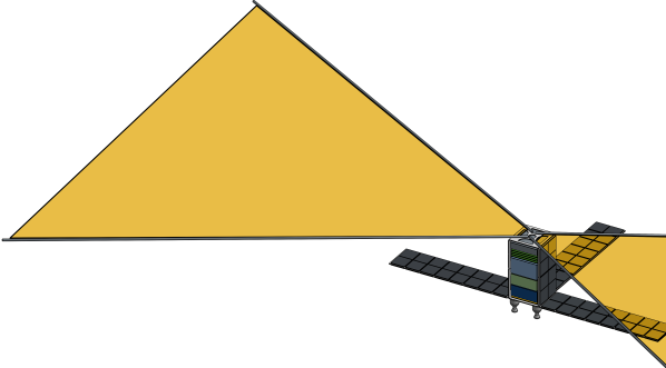
Building on this technological foundation, current experiments focus on redshifts from 6 to 28, targeting the EoR and Cosmic Dawn. Our CosmoCube experiment goes beyond this range, expanding to redshifts from 13 to 150 using a lunar orbiting CubeSat to detect the global 21-cm signal, as shown in Fig. 1. This approach not only promises insights into primordial fluctuations, non-Gaussian statistics deviations, and primordial gravitational waves but also reveals the cosmological model, dark matter properties, and the early Universe’s conditions through the intergalactic medium’s absorption against the CMB. Additionally, by being sensitive to electromagnetic energy injection, the Dark Ages’ 21-cm signal offers a novel way to investigate dark matter models and explore exotic physics beyond current constraints, aiming for significant improvements in data precision Koopmans et al. (2021).
The study by Mondal et al. (2023) provides a precise methodology for probing exotic dark matter models through the analysis of the 21-cm signal from the dark ages, focusing on variations such as millicharged dark matter, dark matter with non-gravitational interactions, and dark matter decay. These models have the potential to significantly alter the thermal and ionization history of the early Universe. By analyzing the power spectrum and global signal variations at high redshifts, models can be constrained, revealing how dark matter interacts with baryonic matter and impacts cosmic structure formation before the appearance of the first stars and galaxies. Although power spectrum analysis provides detailed insights into spatial variations and could reveal subtle dark matter influences, it requires complex observational setups. Due to simpler experimental needs, focusing on the global 21-cm signal is more practical initially, allowing measurements with a single antenna and paving the way for future, more detailed power spectrum studies.
The CosmoCube consists of various novel systems to generate a robust satellite described in the coming chapter. The experiments outlined in this paper extend to the characterization of a compact spectrometer with Xilinx RFSoC ZCU111, which accommodates XCZU28DR-2FFVG1517E. The selection of this RFSoC for the CosmoCube project’s spectrometer represents a strategic decision, leveraging the device’s integration of RF Data Converters, Analog-to-Digital Converters (ADCs), and Digital-to-Analog Converters (DACs) within RFSoC FPGA architecture for precise and efficient spectral analysis for isolating the 21-cm signal from the foreground noises. The compact RFSoC technology suits the cube satellite format, reducing size and power requirements, simplifying operational complexity, and lowering mission costs. By minimizing size and power requirements, the mission can utilize smaller, less expensive launch vehicles and extend operational life, thereby lowering overall mission costs.
The RFSoC’s commercial availability and its broad adoption within engineering and research communities offer access to shared knowledge and resources, enhancing development processes. However, reliance on commercially available technology and community resources introduces dependencies on external developments, potentially constraining project-specific innovations. Additionally, the absence of a radiation-hardened package for this product poses challenges for space applications, necessitating careful management of these limitations. However, Davis et al. (2019) successfully characterized the radiation hardness of the ZCU111, focusing on its resistance to single-event upsets (SEU) and single-event latch-up (SEL) in a proton irradiation environment, using protons with energies ranging from 60 MeV to 200 MeV. The findings confirm the device’s potential for applications in space, particularly in low Earth orbit, highlighting its resilience to radiation-induced errors and the effectiveness of its design modifications in managing latch-up events, with latch-ups occurring at an impressively low rate of approximately once every 90 years. Further testing is advised to fully understand the radiation effects on its high-speed analog components.
Section 2 outlines the CosmoCube framework and lunar far side observations. Section 3 details the spectrometer characterization experiments. Section 4 evaluates FPGA capabilities for mission applicability. Section 5 concludes with final remarks.
2 The far side of the Moon
Deploying a radio telescope on the Moon’s surface involves multiple challenges, such as uncertain lunar ground conditions and the ground spillover effect, which complicates signal detection. Using the Finite Difference Time Domain (FDTD) technique, Bassett et al. (2020) effectively characterized low-frequency radio wave propagation on the lunar far side. Building on this, Burns et al. (2021b) mapped the radio-quiet regions, enhancing the potential for precise observations from lunar missions and mitigating RFI from Earth. Despite these advancements, RFI from other lunar landers and orbiting satellites continues to pose significant challenges, as the effects of such interference are not fully understood due to the limited exploration of the Moon’s far side. The complexity of achieving a soft landing further complicates surface-based missions.
Given these challenges, space agencies’ plans to return to the Moon make lunar missions increasingly advantageous and popular among researchers. Leveraging the interest and resources directed towards lunar exploration can facilitate the deployment of advanced scientific instruments.
Deploying an orbiting satellite offers considerable advantages. Satellites provide enhanced mobility and flexibility, allowing for dynamic observation strategies without the limitations of a fixed position. Additionally, they carry a lower risk of environmental interference compared to surface instruments, which are susceptible to dust and extreme thermal conditions that can impair functionality and longevity. Consequently, an orbital approach not only simplifies operational demands but also proves more cost-effective and efficient for conducting lunar observations.
For satellite-based telescope operations, establishing a direct line of sight with Earth facilitates communication, eliminating the dependency on intermediary relay satellites required by far side landers. This direct transmission method simplifies data exchange and significantly boosts the mission’s overall efficiency.
To optimize the satellite’s performance during nighttime operations, when the 21-cm signal detection is most favorable due to minimal solar noise and maximum Earth’s occultation shielding from terrestrial RFI, careful planning of the orbital distance is critical, which set to be chosen in the range of 100 - 1000 km above the lunar surface. The integration of solar panels and precise sizing of the onboard battery ensure that the CosmoCube utilizes stored energy effectively. These operations necessitate a meticulous balance between energy harvest, storage, and usage, ensuring the satellite’s functions are supported through the lunar night. Thermal analysis for a 12U satellite was carried out under three scenarios: high solar flux during daylight, low solar flux during daylight, and a lunar eclipse, with reference data from a report by NASA (2019). The lowest temperature recorded during the lunar eclipse was -112°C. The extreme temperature variations on the Moon demand a sophisticated thermal management system. This system is crucial to protect the satellite’s electronics and battery, maintain component temperatures within operational ranges, and ensure robust calibration of the system, ensuring that the 21-cm signal is accurately filtered from the captured data.
One of the earliest missions was the Soviet Union’s Luna 3 in 1959. Luna 3 was the first spacecraft to photograph the Moon’s far side, returning grainy but groundbreaking images that revealed a landscape very different from the familiar near side (Lipsky, 1962). Another orbiter, Lunar Reconnaissance Orbiter (LRO), was developed by NASA in 2009, and the pictures are published online as open source (Tooley et al., 2010). China’s Chang’e-4 mission, launched in 2018, marked another significant milestone. Chang’e-4 was the first mission to land on the lunar far side, deploying a lander and a rover, Yutu-2, in the South Pole-Aitken Basin. This mission has provided detailed on-the-ground observations and measurements of the lunar far side, providing valuable data for lunar science and potential future manned missions (Li et al., 2019). Although several missions have been made to the far side of the Moon as yet, none have specifically aimed to detect the 21-cm signal.
The CosmoCube mission parameters, as specified in Table 1, aims to detect the 21-cm hydrogen signal, emphasizing the necessity for precise detection across DC to 128 MHz frequency bandwidth, which covers the science goal frequency range of 10 to 100 MHz. The channelizer’s bin width helps reduce the noise floor of the system whilst increasing the power consumption. Thus, a compromise was made to find an optimum value of 62.5 kHz. This will be detailed in the later chapters. The clock frequencies are carefully synchronized and chosen to facilitate the identification of potential signal components from external sources within our targeted frequency range.
| Conditions | Goals and requirements |
|---|---|
| Science goal for detection of 21-cm signal | 10-100 MHz |
| Total observed bandwidth | DC-128 MHz |
| Channel bandwidth | 62.5 kHz* |
| The flatness throughout spectrum | 0.1 dB* |
| RF data converters’ matched clock frequency | 256 MHz |
| Minimum sensitivity of radiometer | 10 mK |
| Mission 21-cm signal total observation time | minimum 1296 hours |
| Total mission duration | up to 3 years* |
| Orbit altitude | 100-1000 km* |
| Payload size | 12U or 16U* |
-
*
To be defined and justified by the science team.
As the response received at the antenna or the components in the front end does not have a flat response through our frequency of interest, a requirement of 0.1 dB is added. We aim to achieve 10 mK sensitivity along with the passive and active components used in the front end, including the calibrator circuit. The mission requires a minimum of 1296 hours of observation, achieved through various simulations. The mission design also anticipates a significant total observation period, up to three years of operational lifespan, and an orbital altitude optimized for payload effectiveness.
The initial model of CosmoCube is shown in Fig. 2(a) for the deployed satellite structure and in Fig. 2(b) for the stowed satellite structure. To meet its operational energy requirements, the CosmoCube is equipped with solar panels and a battery pack, designed to provide a continuous power supply for the duration of the mission. This setup ensures all satellite components receive regulated power for sustained optimal performance. The satellite’s orientation and stability in lunar orbit are meticulously controlled by altitude and thruster management systems, facilitating precise maneuverability and required elements to deorbit at the end of its lifecycle.
Central to the CosmoCube’s scientific payload is a radiometer, supported by a deployable science antenna for the 21-cm signal acquisition, an RF front end for initial signal processing, and a calibrator to enhance measurement accuracy. The stowed antenna is designed to fit in about 1U package during the launch. One of the elects of the deployed antenna is about 3 m long. Besides the bowtie, the other types of candidate antennas include dipole and blade dipole. However, this paper will not delve into the details of the antenna design, as it is still under development.
3 System Architecture and Instrumentation
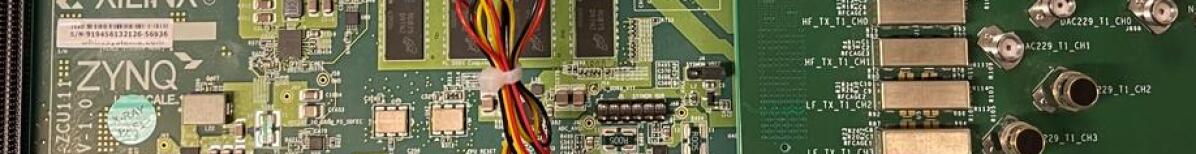
This paper delves into the capability of the RFSoC FPGA, pictured in Fig. 3, for efficient and precise spectral analysis, which is essential for isolating the 21-cm signal from foreground noise. The compact design of the RFSoC is particularly beneficial for the cube satellite format of the CosmoCube project. This integration not only reduces the physical size and power requirements of the satellite but also cuts down on operational complexity and overall mission costs.
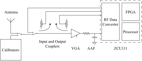
Fig. 4 illustrates CosmoCube’s front-end setup, featuring calibrators parallel to the antenna to simulate observations and generate various noise profiles. This setup, using a Dicke switch-based calibrator system similar to the one in a paper by Razavi-Ghods et al. (2023), adopts Vector Network Analyzer (VNA) principles for calibration. This includes input and output couplers with a switching mechanism for seamless calibration and detection mode transitions. A Variable Gain Amplifier (VGA) compensates for nonlinear gain responses from the antenna and other components, enhancing signal stability. An anti-aliasing filter (AAF) is incorporated to meet Nyquist’s theorem, ensuring accurate signal sampling by avoiding aliasing.
For this setup, three ADCs and one DAC are utilized within the RFSoC. DAC generates waveforms for calibration purposes, whilst two ADCs measure power on the incident and reflected signals on the couplers to measure the reflection coefficients. The final ADC generates a spectrum by processing ADC samples through a channelizer. We have utilized Simulink blocks to design FPGA algorithms.
In the detection mode, the system operates with a single ADC active, while the calibration mode activates two extra ADCs and a DAC. The configuration of single ADC and single DAC is detailed in Fig. 5. In the receiving operation, the signal’s journey through the architecture starts with its capture by the XM500 Balun Board, followed by digitizing the signal via the ADC. Post-ADC, the signal undergoes decimation to reduce the data rate for more manageable processing while maintaining the integrity of the signal information. The Polyphase Filter Bank (PFB) then efficiently separates the signal into multiple frequency bands, optimizing the signal for the Fast Fourier Transform (FFT) process. The FFT block transforms the time-domain data into the frequency domain, facilitating the identification and analysis of specific frequency components. Following this transformation, data is temporarily stored in Block RAM (BRAM), configured as First In First Out (FIFO) for efficient data management. Following FFT, data is routed through buffers and Direct Memory Access (DMA) for efficient data handling, eventually being stored in DDR4 memory. The processed data is then accessible for further analysis externally, completing the reception and initial processing phase, ensuring a comprehensive approach to cosmic signal detection and analysis.
The process of PFB involves segmenting a high-rate data stream into multiple lower-rate streams using input commutators, enhancing manageability and reducing complexity. Each channel is processed by an FIR (Finite Impulse Response) filter with varying coefficients to optimize signal integrity and minimize distortion. This setup manages spectral folding or aliasing when reducing sample rates, ensuring precise frequency band extraction. A subsequent FFT phase aligns and separates the baseband aliases, shifting signals from the time domain to the frequency domain for detailed analysis or further processing. This integrated approach significantly enhances both efficiency and performance in digital communication systems.
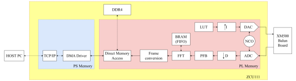
Using a Look-Up Table (LUT) for predefined signal patterns, the DAC precisely converts digital signals into analog form. These signals are then transmitted through the XM500 Balun Board to aid in system calibration. The waveform generation starts with the Numerically Controlled Oscillator (NCO), which produces a precise frequency. This frequency is interpolated to enhance the Signal-to-Noise Ratio (SNR) before being modulated and fed back into the DAC for final analog conversion.
The output of an interpolated signal is the exact representation of the original signal presented at a higher sampling rate. Up-sampling of a signal sampled at F to a higher sample rate (N*F) results in N replications of the original spectrum. Low pass filtering of the result helps to remove unwanted replications resulting in the preservation of the original signal at the required higher sample rate.
Various testing equipment was utilized to characterize the RFSoC for low frequency spectrometer design. The Keysight E8257D generated signals to assess the harmonic distortions and noise performance of the RFSoC ADC. The Keysight PNA-X was used to analyze the data generated by the RFSoC DAC, specifically measuring the Spurious Free Dynamic Range (SFDR) in spectrum analyzer mode. Furthermore, the Keysight PNA-X was used to generate two-tone signals.
Floating-point operations provide a wide range of values and precision, but they require more resources and have higher latency. Furthermore, floating-point numbers are prone to precision loss due to their limited representation of real numbers. This limitation becomes pronounced when dealing with large values, leading to information loss in significant digits. Conversely, fixed-point operations are more resource-efficient and have lower latency, although they have a limited range and precision. While it offers less dynamic range compared to floating-point arithmetic, because of the rounding errors inherent in fixed-point calculations. However, for our channelizer, where efficient resource utilization is crucial, fixed-point arithmetic is utilized due to its lower overhead. For the post-processing of the data, we worked with floating-point arithmetic on Matlab to plot the measurements.
In the CosmoCube project, the ZCU111 RFSoC FPGA’s DAC setup with a sample rate of 2048 MSPS for 65536 samples per clock cycle. A 256 MHz clock frequency was chosen to cover the necessary band up to 128 MHz. Although our mission targets frequencies up to 100 MHz, the 128 MHz bandwidth provides a margin for signal processing and filtering, addressing potential out-of-band noise or interference. A higher ADC clock frequency helps avoid aliasing and accurately sample the signal, ensuring stable observation and acquirement of the spectrum with the channelizer. The 32-bit stream data width offers a high dynamic range, preserving signal integrity.
The samples are transmitted to an external source at a data rate of 655 kbps. This is a relatively high speed, requiring substantial data storage in the payload before transmission to Earth. Assuming the payload is at 1000 km above the moon, we have 43 minutes of data collection during Earth’s occultation. At a data rate of 655 kbps, this results in approximately 201 MB of data, which is significant. However, due to averaging within FPGA, this data will be reduced to below 4 MB per observation on the far side.
4 Hardware Characterization
This section outlines the methodology for measuring the accuracy, efficiency, and overall performance of the RF data converters through a series of systematic tests. This analysis outlines testing methods for assessing the performance of these converters in capturing low-frequency signals from the dark ages. Accurate characterization ensures the RFSoC meets the sensitivity and dynamic range required for studying cosmic phenomena.
4.1 Single tone measurements
In an initial characterization, the DAC and ADC of the RF Data Converter of the RFSoC are assessed by single-tone measurements within the bandwidth of DC to 128 MHz. However, the characterization of this low frequency introduces challenges in distinguishing spurious signals generated by the device under test, ZCU111, and the testing equipment used in this experiment. The commercially available spectrum analyzers trigger harmonic generation attributed to the first up/down converter mixers in its signal chain saturating. A substantial fraction of our observed spectrum consists of harmonic frequencies of fundamental signals. Consequently, it is essential to carefully control mixer input levels to prevent overdriving. We employed various notch filters to differentiate harmonics produced by the DACs of RFSoC from the spectrum analyzer PNA-X. Additionally, an anti-aliasing filter with a cutoff frequency of 105 MHz was utilized to remove aliased frequency components that could otherwise distort the analysis within our bandwidth. In contrast, various combinations of low-pass and high-pass filters built in-house are utilized in assessing RFSoC’s ADC performance as they eliminate harmonics generated by the signal generators. The list of used filters is given in Table 2.
| Cutoff frequencies | Filter model | Test used for |
|---|---|---|
| 9-15 MHz BPF | ZX75-12-S+ | ADC and DAC |
| 22 MHz 9th Chebyshev LPF | designed in-house | ADC |
| 26 MHz 9th Chebyshev LPF | designed in-house | ADC |
| 37 MHz 9th Chebyshev LPF | designed in-house | ADC |
| 62 MHz 9th Chebyshev LPF | designed in-house | ADC |
| 105 MHz 9th Chebyshev LPF | designed in-house | ADC |
| 25 MHz HPF | CHPFL-0025-BNC | ADC and DAC |
| 40-250 MHz BPF | designed in-house | ADC and DAC |
| 90 MHz HPF | BHP-100 | ADC and DAC |
| 88-108 MHz BSF | BSF-108+ | ADC and DAC |
| 160 MHz HPF | SHP-175+ | ADC and DAC |
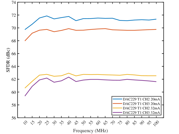
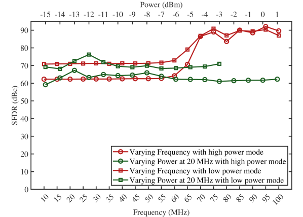
The 14-bit DAC within the RFSoC can be optimized for low SNR or high linearity. SNR optimization focuses on maximizing the signal’s power relative to background noise, employing noise reduction techniques to enhance signal clarity. Conversely, linearity optimization aims to maintain signal fidelity across its operating range, using strategies to ensure the output accurately reflects the input without distortion. Selection of SNR optimized decoder triggers a requirement of characterizing spurious signals within a bandwidth of 300 MHz for fundamental signals up to 100 MHz. The sample rate was chosen to be 2048 MSPS, and the clock frequency was set to 256 MHz. Fig. 6 illustrates the SFDR characterization, the ratio between the fundamental and the next highest spurious signal excluding the DC component, of two DACs with two different decoder modes, low power with 20 mA and high power with 32 mA operations. The output power of -3 dBm is observed within the bandwidth with varying frequency for low power mode, whilst +1 dBm was acquired throughout the band for high power mode, holding for the same digital code in each case. Only about a 0.06 dBm decrease was observed in the fundamental signal powers throughout the frequency range. As the band-pass filter (BPF), high-pass filter (HPF) or band-stop filter (BSF) is used, the output power is matched to separate measurements of maximum values for the frequency to eliminate power losses introduced by the filters. The datasheet of RFSoC indicates another power mode, 3 V operation, requiring reconfiguration of the Infenion IRPS5401 power supply within the evaluation board with their programming tools providing +5 dBm output with a higher voltage setting. Hence, this was not investigated. Another limitation of the Simulink RF Data Converter block is that it only supports 20 mA operation, which was overcome by adjustment of this value in the Xilinx Vivado tool.
Although the RFSoC is integrated with eight 14-bit DACs, only two have been investigated as XM500 balun board consists of 2 to 1 Mini-Circuits TCM2-33WX+ transformers operating between 10 and 3000 MHz. While the other two DACs work with high-frequency applications, the last four are two port differential outputs. The two DACs, Tile229CH2 and Tile229CH3, show differences in their performances, which might be explained by external components such as RF transformers or SMA connectors, which are screw-on and fiddle easily as the connection changes each time in the daughter board. Another explanation is that the RFSoC chip shows these varieties within its structure.
The SFDR was mainly dominated by the 2nd and 3rd harmonics generated by the DACs. The DACTile229CH2 demonstrated better performance, with about 71 dBc for low power and 63 dBc for high power mode. The datasheet of Xilinx shows SFDR measurements in a minimum of 240 MHz range and with a sampling rate of 6.4 GSPS, and compared to this, our values align with the datasheet values of 71 dBc for low power and 64 dBc for high power. Although the SFDR difference is apparent between the two DACs, the generated fundamental signal power was the same for both DACs. This shows that in order to implement robust calibration methods, we have to compensate for the difference between these ports.
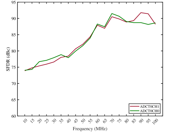
Various low-pass filters (LPF) were used in the measurement of the signal through ADC, as listed in Table 2. Datasheet of Xilinx (2023) indicates +1 Vpp as the full-scale range for the ADCs. The power levels for each measurement matched to -1 dBFS, corresponding to 3 dBm power for a 50 Ohms system, in order to eliminate clipping and compensate for the losses introduced by the filters. ADCTile224CH1 and ADCTile224CH0, separately, employ a 65536-point FFT to analyze incoming signals, with a channel bandwidth of 3.9 kHz with PFB. The clock signal of 256 MHz is employed with a 2048 MSPS sampling rate. 100-spectrum data was acquired, and the average was taken.
The improvement with the SFDR was observed with the higher frequencies, as the harmonics generated in the ADC fall out of our bandwidth from 65 MHz and above, creating their folded frequency components triggered in the Nyquist range. Similar to the RF transformers used in the balun board for DAC outputs, the same components are located in the ADC receive chain. Xilinx datasheet illustrates 2nd and 3rd harmonic distortions from -68 to -78 dBc at 240 MHz signal with -1 dBFS input and 2GHz clock frequency. The SFDR is similar to the one in the datasheet for low frequency, where harmonics are within our spectrum. Conversely, the SFDR excluding harmonics on the Xilinx datasheet indicates a typical 85 dBc at 240 MHz operation. We acquired about 90 dBc SFDR for the higher frequencies. The two ports’ similar behavior and the slight differences might be explained as the on-chip variation of these legs or the traces leading up to them.
4.2 Spectrometer design
Following the characterization of DACs and ADCs within the RFSoC, we have developed a spectrometer with PFB to assess its qualification for CosmoCube. For adequate and power-efficient capture of the 21-cm signal from the Dark Ages, the PFB configuration utilized in this setup is designed to generate 81920 coefficients for each frame comprising 4096 samples, yielding a bin width of 62.5 kHz.
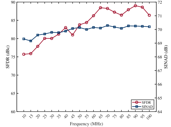
The SFDR and Signal-to-Noise and Distortion Ratio (SINAD) of the designed spectrometer are illustrated in Fig. 8. SINAD encompasses both, noise and distortion, including spurious signals, but excludes DC relative to the fundamental signal’s magnitude. The RMS of the fundamental signal reflects the signal’s effective amplitude. The root-sum-square (RSS) of noise and spurs provides a single figure for their cumulative effect on its quality. The CW signals were generated by Keysight E8257D. The LPFs and HPFs were combined to create the BPFs. Although the BPFs mitigate the noise floor generated by the signal generator to present at the input of the ADC, it is very hard to filter the noise floor around the peak power. The fundamental power level measured at the ADC captured spectrum when input was -1 dBFS only changed by -0.22 dBFS at the highest frequency because of the quantization noise. Hence, this loss was ignored, and the fundamental power levels received at the ADC were matched over the frequency band.
The low-frequency SFDR was found to be similar to the previous results, with 65536 FFT length for the same ADC setting, and the levels of the harmonics were the same. And, these values are still compatible for a spectrometer to be used in a space-based radiometer. The SINAD remains relatively stable across the frequency range, indicating consistent overall signal integrity within our bandwidth and performance required in cosmic observations.
Table 3 demonstrates the difference between the maximum available FFT length, as presented in the previous Section 4.1, and the designed spectrometer presented here. The compromise is given in terms of power budget and robust signal detection. This table highlights differences in specifications set in the Matlab model, such as sampling rate, clock frequency, FFT length, and the number of coefficients in the PFB, as well as FFT bin width. Additionally, on-chip utilization metrics received through the Vivado tool, including Look-Up Tables (LUT), Block RAM (BRAM), Digital Signal Processing (DSP) utilization, and power consumption, are detailed, reflecting the efficiency and resource demands of each setup. Although a larger FFT bin width results in reduced spectral resolution, it enhances power efficiency, and the spectral resolution provided by the spectrometer is adequately sufficient for analyzing the global 21-cm signal.
| Specifications | Maximum | Spectrometer |
|---|---|---|
| Sampling Rate | 2048 MSPS | 2048 MSPS |
| Clock Frequency | 256 MHz | 256 MHz |
| FFT Length | 65536 | 4096 |
| PFB Number of Coefficients | 262144 | 81920 |
| FFT bin BW | 3.9 kHz | 62.5 kHz |
| On-chip Utilization | ||
| LUT | 6.37% | 3.27% |
| LUTRAM | 0.87% | 0.49% |
| BRAM | 87.27% | 23.75% |
| DSP | 1.57% | 1.29% |
| Power Consumption | 6.1 W | 5.45 W |
4.2.1 Key metrics for ADC performance for spectrometer
The spectrometer is characterized by typical metrics like Effective Number of Bits (ENOB) and Noise Spectral Density (NSD), which quantifies the converters’ precision and noise levels, thereby influencing the overall fidelity of signal detection and analysis. Eq. 1 gives the ENOB, where the first component is the ratio of the fundamental signal to all the components of the noise and distortion, excluding DC. The second part, -1.76 dB, indicates the full-scale sine wave’s quantization error in the 12-bit ADC. The final component of the equation, as given in Kester (2009), normalizes to the reduced power used compared to the full scale given in the datasheet. The denominator converts the binary resolution of the ADC into the dB scale.
| (1) |
A wider measurement bandwidth will include more noise power, as the total noise is the integration of NSD across the bandwidth. Therefore, to maintain a high Signal-to-Noise Ratio (SNR) in the system design, we considered the bandwidth over which the spectrometer operates. NSD is calculated with Eq. 2, where the second component illustrates the limitation with a set sampling frequency, as shown in Xilinx (2017). Since measurements compared with the signal are less than ADC’s full scale utilized, the normalization factor appears in the equation.
| (2) |
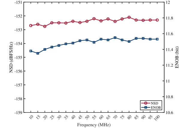
The plot depicted in Fig. 9 demonstrates the spectrometer’s consistent performance across a range of frequencies from 10 MHz to 100 MHz, as evidenced by the stable measurements of NSD and ENOB. This stability in NSD and ENOB is indicative of the system’s robust ability to maintain accuracy and resolution under varied testing conditions using a PFB with 62.5 kHz bin widths.
ENOB across the frequency spectrum shows minimal deviation from the expected values of 12 bits despite slight variations due to signal distortion. The typical ENOB value of 11.5 bits confirms that lower distortion correlates with improved ENOB, which benefits from the normalization adjustments applied in the calculations. This adaptation helps mitigate the impact of low-frequency challenges, which are typically pronounced in radio astronomy. Although the Xilinx datasheet does not provide information on ENOB, the results match those of ADC converters used in radiometers. Characterization of the harmonics generated by the ADC remains significant for low-frequency radio astronomy.
Further analysis indicates that NSD is preferable to ENOB as a metric for assessing ADC’s performance through SNR, which excludes harmonics. As the signal frequency nears the ADC’s clock frequency, the ADC has limited time to accurately measure the signal’s amplitude before the next sampling event, which compresses the dynamic range in the digital output. Additionally, the effectiveness of noise shaping and techniques dependent on oversampling or filtering across multiple samples diminishes, resulting in an increase in NSD and further distorting the signal representation. The measured NSD values around -152.5 dBFS/Hz are better than the typical -150 dBFS/Hz at 240 MHz reported by Xilinx (2023) for similar conditions, this discrepancy likely stems from nonlinear effects introduced by the RF hardware, specifically the transformers used at balun board.
4.2.2 Two-tone test
From a mathematical standpoint, implementing the system’s transfer function within the framework of a Taylor series yields a spectrum of frequency products in the output. The two-tone present at the input of the transfer function yields output components with different frequency points and coefficients. The third-order products of () and (), 3rd-order intermodulation distortion (IMD3), are considerably closer to the fundamental frequency. Consequently, attempts at their extraction can trigger a notable reduction in the SNR, effectively compromising the overall quality of the signal. In the Taylor series, their coefficients result in a 1 to 3 slope, meaning they amplify three times quicker than the fundamental signal with respect to input amplitude.
The PNA-X was used to generate CW two tones with a spacing of 0.5 MHz. Fig. 10 demonstrates the lower and upper IM3 values. It can be seen that around -5 dBFS, IM3 drops below -80 dBc. The data aligns with Xilinx datasheet values, indicating a -78 dBc performance of IM3 for the ADC at 240 MHz, with -7 dBFS input amplitude and 20 MHz spacing.
When examining the upper and lower IM3 products in a nonlinear device, differences in their behavior can indicate the presence of memory effects, which refer to how the past behavior of the signal influences the current performance of the ADC. This often causes the device to behave differently based on its previous states, especially under varying signal conditions. Specifically, if the upper and lower IM3 products differ significantly, it might indicate asymmetrical memory effects. These effects can occur due to factors such as thermal lag, power supply variations, or component mismatches within the ADC that are affected by the envelope frequency. Hence, this was investigated, and it was revealed that the discrepancies are negligible.
4.2.3 PFB channel leakage
Channel leakage occurs when energy from a signal in a given frequency channel spreads into adjacent channels, potentially leading to significant distortions in the data collected. Even with narrow band filtering of PFB, the finite length of the FFT window and the properties of the window function itself can result in leakage. The 21-cm line is extremely faint and situated among various stronger astrophysical signals. Leakage across frequency channels can lead to a misinterpretation of these weak signals by either overwhelming the 21-cm signal with noise from stronger adjacent channels or by blending important spectral features.
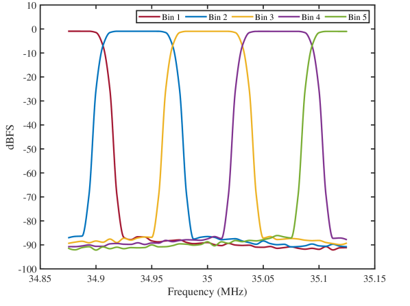
Sweeping signals at a frequency of 6.25 kHz were utilized to assess the channel leakage performance, as illustrated in Fig. 11, of the PFB, which was configured for a channel width of 62.5 kHz for our spectrometer. While spectral leakage can be reduced, this requires more calculations in the FPGA, either by increasing sample numbers, reducing bin width, or implementing overlapping windows.
4.3 Loopback test
The previous experiment generated the signal using a signal generator to assess spectrometer performance. However, in CosmoCube, we will employ a calibration methodology that utilizes both DACs and ADCs within the RFSoC. Hence, we measured the loopback, where the coax cable connects the ADC of the RFSoC to the DAC of the same RFSoC by only employing AAF between the DAC and ADC connection. The losses between the frequency points were compensated.
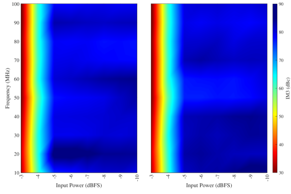
Fig. 12 demonstrates the SFDR performance of the spectrometer by varying frequency and input power. Two modes, high and low power, of the same DAC, have been investigated. Our observations indicate that the SFDR remains consistent when either or both the 2nd and 3rd harmonics are within the measured bandwidth, which corresponds to frequency up to 60 MHz. In scenarios where only folded frequency components are present within the bandwidth, both low and high-power modes exhibited improved performance, yet the SFDR was comparable between the two modes. Although the significant shift in SFDR from 60 MHz to 70 MHz necessitates adjustments to the calibration algorithm, the generally stable performance of the SFDR across two bands, low and high frequency, suggests that managing the calibration should be straightforward.
Additionally, varying the input power at 20 MHz confirmed that the dynamic range remains stable in both high and low power modes. The low-power mode consistently maintains a narrower SFDR spread, which suggests that it is more resilient to spectral anomalies or harmonic distortions under varied testing conditions. The robustness of the SFDR across the entire bandwidth significantly assists in the calibration process by ensuring consistent measurement accuracy and reliability.
4.4 Noise measurements with varying temperatures and integration time
A lower noise floor enhances sensitivity to the extremely faint 21-cm signal, which is crucial for distinguishing them from background noise. Accurate noise floor characterization improves data reliability, enabling more precise insights into the Universe’s earliest structures.
We used a thermal chamber to test the stability of the ZCU111 RFSoC under various temperature conditions, adhering to the device’s specified operating range of 0∘C to 45∘C, as indicated in its datasheet. Although thermal systems will be in place to ensure temperature stability inside the CubeSat, we used a thermal chamber to verify that the spectrometer could reliably maintain its performance and accuracy in the extreme thermal environments encountered in space. By systematically adjusting the temperature within the chamber, we observed the device’s response to thermal stress, ensuring that it could handle the fluctuations without degrading its functionality.
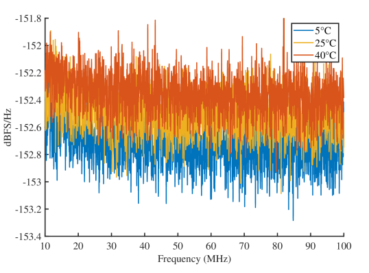
We recorded a noise floor of approximately -152.5 dBFS/Hz at an environmental temperature of 25∘C, as shown in Fig. 13. The datasheet for the ZCU111 specifies a typical noise floor of about -152 dBFS/Hz at a frequency of 240 MHz. The observed 0.2 dB variation under extreme temperature conditions confirms the spectrometer’s stable operation, demonstrating its robustness and reliability for precise measurements in the challenging thermal environment of space.
The integration time is calculated by multiplying the number of samples, 2048, acquired by the ADC by the number of averaged frames of 250, 500, and 2500 and then dividing the result by the sampling rate of 2048 MSPS. Fig. 14 illustrates how the noise floor varies with different integration times, demonstrating the impact of integration duration on the stability and clarity of the signal detected by the spectrometer.
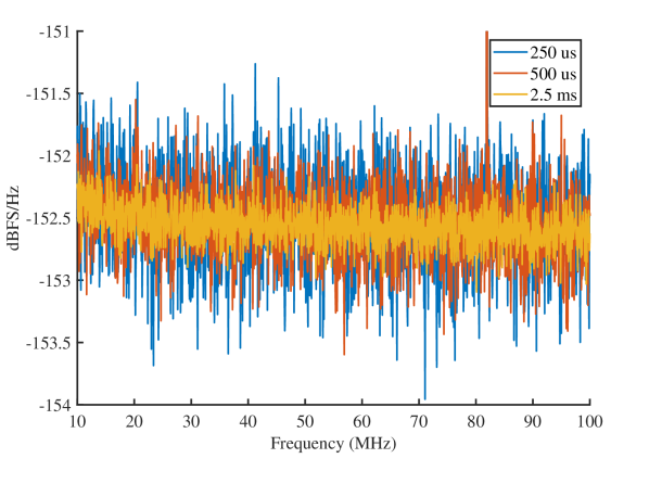
The noise floor of the same ADC was measured on two separate occasions, showing a variation of approximately dB. This is comparable to the dB variations observed by Liu et al. (2020) in their analysis of the ZCU111 for wideband radiometer applications. The variation between these two works might be evidence of temperature stability, as the board’s temperature in this work was maintained in a thermal chamber for some time to ensure stability.
5 Conclusions
In conclusion, the CosmoCube instrument represents an advancement in lunar and space-based radio astronomy, particularly in exploring the faint 21-cm hydrogen line from the Dark Ages. By overcoming terrestrial limitations and harnessing innovative technologies such as the Xilinx RFSoC, CosmoCube provides unprecedented sensitivity and resolution, offering new insights into the early Universe’s structure and evolution. Utilizing a channelizer in the spectrometer, we achieved an ENOB of approximately 11.5 and an NSD of around -152.5 dBFS/Hz, highlighting the system’s high precision and low noise performance across the frequency range of interest. Even with the exceptional performance showing only a 0.2 dB variation under extreme temperatures, thermal systems are still required to maintain stability, particularly for the calibration of the system. Furthermore, the need for stringent filtering techniques was evident, as harmonic levels impacted data integrity. The implementation of specialized filters and characterization of these spurious signals will be critical in future refinements to reduce signal contamination and enhance the overall quality of the cosmological data collected by CosmoCube. Further analysis of power consumption will be made to optimize the balance between system performance and operational longevity, ensuring the mission’s sustainability and efficiency in the harsh conditions of space.
Acknowledgements
We acknowledge the support by the UK Space Agency (UKSA) with the funding codes UKSA ST/Z000548/1 and UKSA ST/Z000556/1. Kaan Artuc thanks RF-Lambda for the funding. Eloy de Lera Acedo acknowledges the Science and Technology Facilities Council (STFC) for their funding support through an STFC Ernest Rutherford Fellowship.
Data Availability
The data underlying this article will be shared on reasonable request to the corresponding author.
References
- Bale et al. (2023) Bale, S. D., Bassett, N., Burns, J. O., Jones, J. D., Goetz, K., Hellum-Bye, C., Hermann, S., Hibbard, J., Maksimovic, M., McLean, R., Monsalve, R., O’Connor, P., Parsons, A., Pulupa, M., Pund, R., Rapetti, D., Rotermund, K. M., Saliwanchik, B., Slosar, A., Sundkvist, D., & Suzuki, A., 2023. Lusee ’night’: The lunar surface electromagnetics experiment, arXiv.
- Barkana (2016) Barkana, R., 2016. The rise of the first stars: Supersonic streaming, radiative feedback, and 21-cm cosmology, Physics Reports, 645, 1–59.
- Barry et al. (2016) Barry, N., Hazelton, B., Sullivan, I., Morales, M. F., & Pober, J. C., 2016. Calibration requirements for detecting the 21cm epoch of reionization power spectrum and implications for the ska, mnras, 461, 3135–3144.
- Bassett et al. (2020) Bassett, N., Rapetti, D., Burns, J. O., Tauscher, K., & MacDowall, R., 2020. Characterizing the radio quiet region behind the lunar farside for low radio frequency experiments, Advances in Space Research, 66, 1265–1275.
- Bentum et al. (2020) Bentum, M., Verma, M., Rajan, R., Boonstra, A., Verhoeven, C., Gill, E., van der Veen, A., Falcke, H., Wolt, M. K., Monna, B., Engelen, S., Rotteveel, J., & Gurvits, L., 2020. A roadmap towards a space-based radio telescope for ultra-low frequency radio astronomy, Advances in Space Research, 65, 856–867.
- Bernardi et al. (2010) Bernardi, G., de Bruyn, A. G., Harker, G., Brentjens, M. A., Ciardi, B., Jelić, V., Koopmans, L. V. E., Labropoulos, P., Offringa, A., Pandey, V. N., Schaye, J., Thomas, R. M., Yatawatta, S., & Zaroubi, S., 2010. Foregrounds for observations of the cosmological 21cm line - ii. westerbork observations of the fields around 3c196 and the north celestial pole, A&A, 522, A67.
- Bernardi et al. (2016) Bernardi, G., Zwart, J. T. L., Price, D., Greenhill, L. J., Mesinger, A., Dowell, J., Eftekhari, T., Ellingson, S. W., Kocz, J., & Schinzel, F., 2016. Bayesian constraints on the global 21-cm signal from the cosmic dawn, mnras, 461, 2847–2855.
- Bevins et al. (2022) Bevins, H. T. J., de Lera Acedo, E., Fialkov, A., Handley, W. J., Singh, S., Subrahmanyan, R., & Barkana, R., 2022. A comprehensive bayesian reanalysis of the saras2 data from the epoch of reionization, mnras, 513, 4507–4526.
- Bowman et al. (2008) Bowman, J. D., Rogers, A. E. E., & Hewitt, J. N., 2008. Toward empirical constraints on the global redshifted 21 cm brightness temperature during the epoch of reionization, ApJ, 676, 1.
- Burns et al. (2021a) Burns, J., Hallinan, G., Chang, T.-C., Anderson, M., Bowman, J., Bradley, R., Furlanetto, S., Hegedus, A., Kasper, J., Kocz, J., Lazio, J., Lux, J., MacDowall, R., Mirocha, J., Nesnas, I., Pober, J., Polidan, R., Rapetti, D., Romero-Wolf, A., Slosar, A., Stebbins, A., Teitelbaum, L., & White, M., 2021a. A lunar farside low radio frequency array for dark ages 21-cm cosmology.
- Burns et al. (2021b) Burns, J. O., MacDowall, R., Bale, S., Hallinan, G., Bassett, N., & Hegedus, A., 2021b. Low radio frequency observations from the moon enabled by nasa landed payload missions, The Planetary Science Journal, 2, 44.
- Byrne et al. (2019) Byrne, R., Morales, M. F., Hazelton, B., Li, W., Barry, N., Beardsley, A. P., Joseph, R., Pober, J., Sullivan, I., & Trott, C., 2019. Fundamental limitations on the calibration of redundant 21 cm cosmology instruments and implications for hera and the ska, AJ, 875, 70.
- Chen & Miralda-Escudé (2004) Chen, X. & Miralda-Escudé, J., 2004. The spin-kinetic temperature coupling and the heating rate due to lyman alpha scattering before reionization: Predictions for 21cm emission and absorption, ApJ, 602, 1–11.
- Chen et al. (2021) Chen, X., Yan, J., Deng, L., Wu, F., Wu, L., Xu, Y., & Zhou, L., 2021. Discovering the sky at the longest wavelengths with a lunar orbit array, Philosophical Transactions of the Royal Society A: Mathematical, Physical and Engineering Sciences, 379, 20190566.
- Chen et al. (2024) Chen, X., Gao, F., Wu, F., Zhang, Y., Wang, T., Liu, W., Zou, D., Deng, F., Gong, Y., He, K., Li, J., Sun, S., Suo, N., Wang, Y., Wu, P., Xu, J., Xu, Y., Yue, B., Zhang, C., Zhou, J., Zhou, M., Zhu, C., & Zhu, J., 2024. Large-scale array for radio astronomy on the farside (laraf), Philosophical Transactions of the Royal Society A: Mathematical, Physical and Engineering Sciences, 382, 20230094.
- Cumner et al. (2022) Cumner, J., de Lera Acedo, E., de Villiers, D., Anstey, D., Kolitsidas, C., Gurdon, B., Fagnoni, N., Alexander, P., Bernardi, G., Bevins, H., Carey, S., Cavillot, J., Chiello, R., Craeye, C., Croukamp, W., Ely, J., Fialkov, A., Gessey-Jones, T., Gueuning, Q., Handley, W., Hills, R., Josaitis, A., Kulkarni, G., Magro, A., Maiolino, R., Meerburg, P., Mittal, S., Pritchard, J., Puchwein, E., Razavi-Ghods, N., Roque, I., Saxena, A., Scheutwinkel, K., Shen, E., Sims, P., Smirnov, O., Spinelli, M., & Zarb-Adami, K., 2022. Radio antenna design for sky-averaged 21cm cosmology experiments: The reach case, Journal of Astronomical Instrumentation, 11.
- Datta et al. (2016) Datta, A., Bradley, R., Burns, J. O., Harker, G., Komjathy, A., & Lazio, T. J. W., 2016. The effects of the ionosphere on ground-based detection of the global 21 cm signal from the cosmic dawn and the dark ages, ApJ, 831.
- Davis et al. (2019) Davis, P., Lee, D. S., Learn, M., & Thorpe, D., 2019. Single-event characterization of the 16 nm finfet xilinx ultrascale+tm rfsoc field-programmable gate array under proton irradiation, 2019 IEEE Radiation Effects Data Workshop, pp. 1–5.
- de Lera Acedo et al. (2022) de Lera Acedo, E., de Villiers, D. I. L., Razavi-Ghods, N., Handley, W., Fialkov, A., Magro, A., Anstey, D., Bevins, H. T. J., Chiello, R., Cumner, J., Josaitis, A. T., Roque, I. L. V., Sims, P. H., Scheutwinkel, K. H., Alexander, P., Bernardi, G., Carey, S., Cavillot, J., Croukamp, W., Ely, J. A., Gessey-Jones, T., Gueuning, Q., Hills, R., Kulkarni, G., Maiolino, R., Meerburg, P. D., Mittal, S., Pritchard, J. R., Puchwein, E., Saxena, A., Shen, E., Smirnov, O., Spinelli, M., & Zarb-Adami, K., 2022. Bayesian constraints on the global 21-cm signal from the cosmic dawn, Nature Astronomy, 6, 984–998.
- DeBoer et al. (2017) DeBoer, D. R., Parsons, A. R., Aguirre, J. E., Alexander, P., Ali, Z. S., Beardsley, A. P., Bernardi, G., Bowman, J. D., Bradley, R. F., Carilli, C. L., Cheng, C., de Lera Acedo, E., Dillon, J. S., Ewall-Wice, A., Fadana, G., Fagnoni, N., Fritz, R., Furlanetto, S. R., Glendenning, B., Greig, B., Grobbelaar, J., Hazelton, B. J., Hewitt, J. N., Hickish, J., Jacobs, D. C., Julius, A., Kariseb, M., Kohn, S. A., Lekalake, T., Liu, A., Loots, A., MacMahon, D., Malan, L., Malgas, C., Maree, M., Martinot, Z., Mathison, N., Matsetela, E., Mesinger, A., Morales, M. F., Neben, A. R., Patra, N., Pieterse, S., Pober, J. C., Razavi-Ghods, N., Ringuette, J., Robnett, J., Rosie, K., Sell, R., Smith, C., Syce, A., Tegmark, M., Thyagarajan, N., Williams, P. K. G., & Zheng, H., 2017. Hydrogen epoch of reionization array (hera), Publications of the Astronomical Society of the Pacific, 129, 045001.
- Furlanetto et al. (2006) Furlanetto, S. R., Oh, S. P., & Briggs, F. H., 2006. Cosmology at low frequencies: The 21cm transition and the high-redshift universe, Physics Reports, 433, 181–301.
- Ghosh et al. (2012) Ghosh, A., Prasad, J., Bharadwaj, S., Ali, S. S., & Chengalur, J. N., 2012. Characterizing foreground for redshifted 21cm radiation: 150mhz giant metrewave radio telescope observations, mnras, 426, 3295–3314.
- Goel et al. (2022) Goel, A., Bandyopadhyay, S., Lazio, J., Goldsmith, P., Bacon, D., Amara, A., Furnaletto, S., McGarey, P., Rafizadeh, R., Delapierre, M., Arya, M., Pisanti, D., Gupta, G., Chahat, N., Stoica, A., Nesnas, I., Quadrelli, M., Hallinan, G., Jenks, K., & Wilson, R., 2022. Probing the cosmic dark ages with the lunar crater radio telescope, arXiv.
- Hills et al. (2018) Hills, R., Kulkarni, G., Meerburg, P. D., & Puchwein, E., 2018. Concerns about modelling of the edges data, Nature, 564, E32 – E34.
- Jia et al. (2018) Jia, Y., Zou, Y., Ping, J., Xue, C., Yan, J., & Ning, Y., 2018. The scientific objectives and payloads of chang’e-4 mission, Planetary and Space Science, 162, 207–215.
- Kester (2009) Kester, W., 2009. Tutorial mt-003: Taking the mystery out of the infamous formula, “snr = 6.02n + 1.76 db,” and why you should care, Online, Accessed: 2023-04-30.
- Klein Wolt et al. (2024) Klein Wolt, M., Falcke, H., & Koopmans, L., 2024. The astronomical lunar observatory (alo) - probing the cosmological dark ages and cosmic dawn with a distributed low-frequency radio array on the lunar far side, American Astronomical Society Meeting Abstracts, 243, 264.01.
- Koopmans et al. (2021) Koopmans, L., Barkana, R., Bentum, M., Bernardi, G., Boonstra, A.-J., Bowman, J., Burns, J., Chen, X., Datta, A., Falcke, H., Fialkov, A., Gehlot, B., Gurvits, L., Jelić, V., Klein-Wolt, M., Koopmans, L., Lazio, J., Meerburg, D., Mellema, G., Mertens, F., Mesinger, A., Offringa, A., Pritchard, J., Semelin, B., Subrahmanyan, R., Silk, J., Trott, C., Vedantham, H., Verde, L., Zaroubi, S., & Zarka, P., 2021. Peering into the dark (ages) with low-frequency space interferometers, Experimental Astronomy, 51, 1641–1676.
- Lai et al. (2020) Lai, J., Xu, Y., Bugiolacchi, R., Meng, X., Xiao, L., Xie, M., Liu, B., Di, K., Zhang, X., Zhou, B., Shen, S., & Xu, L., 2020. First look by the yutu-2 rover at the deep subsurface structure at the lunar farside, Nature Communications, 11.
- Lawrence et al. (1964) Lawrence, R., Little, C., & Chivers, H., 1964. A survey of ionospheric effects upon earth-space radio propagation, Proceedings of the IEE, 52, 4–27.
- Li et al. (2019) Li, W., Pober, J. C., Barry, N., Hazelton, B. J., Morales, M. F., Trott, C. M., Lanman, A., Wilensky, M., Sullivan, I., Beardsley, A. P., Booler, T., Bowman, J. D., Byrne, R., Crosse, B., Emrich, D., Franzen, T. M. O., Hasegawa, K., Horsley, L., Johnston-Hollitt, M., Jacobs, D. C., Jordan, C. H., Joseph, R. C., Kaneuji, T., Kaplan, D. L., Kenney, D., Kubota, K., Line, J., Lynch, C., McKinley, B., Mitchell, D. A., Murray, S., Pallot, D., Pindor, B., Rahimi, M., Riding, J., Sleap, G., Steele, K., Takahashi, K., Tingay, S. J., Walker, M., Wayth, R. B., Webster, R. L., Williams, A., Wu, C., Wyithe, J. S. B., Yoshiura, S., & Zheng, Q., 2019. First season mwa phase ii epoch of reionization power spectrum results at redshift 7, The Astrophysical Journal, 887, 141–161.
- Lian et al. (2020) Lian, X., Xu, H., Zhu, Z., & Hu, D., 2020. Contribution of galactic free–free emission to the foreground for eor signal in ska experiments, mnras, 496, 1232–1242.
- Lipsky (1962) Lipsky, Y. N., 1962. A study of photographs of the far side of the moon and description of singular features revealed on its surface, The Moon, 14, 7–24.
- Liu et al. (2020) Liu, C., Jones, M. E., & Taylor, A. C., 2020. Characterizing the performance of high-speed data converters for RFSoC-based radio astronomy receivers, Monthly Notices of the Royal Astronomical Society, 501, 5096–5104.
- Mahesh et al. (2021) Mahesh, N., Bowman, J. D., Mozdzen, T. J., Rogers, A. E. E., Monsalve, R. A., Murray, S. G., & Lewis, D., 2021. Validation of the edges low-band antenna beam model, ApJ, 162, 38.
- Mondal et al. (2023) Mondal, R., Barkana, R., & Fialkov, A., 2023. Constraining exotic dark matter models with the dark ages 21-cm signal, mnras, 527, 1461–1471.
- Monsalve et al. (2023) Monsalve, R. A., Altamirano, C., Bidula, V., Bustos, R., Bye, C. H., Chiang, H. C., Diaz, M., Fernandez, B., Guo, X., Hendricksen, I., Hornecker, E., Lucero, F., Mani, H., McGee, F., Mena, F. P., Pessoa, M., Prabhakar, G., Restrepo, O., Sievers, J. L., & Thyagarajan, N., 2023. Mapper of the igm spin temperature (mist): Instrument overview, arXiv.
- Morales & Wyithe (2010) Morales, M. F. & Wyithe, J. S. B., 2010. Reionization and cosmology with 21-cm fluctuations, ANNUAL REVIEW OF ASTRONOMY AND ASTROPHYSICS, 48, 127–171.
- NASA (2019) NASA, 2019. Cross-program design specification for natural environments (dsne), Tech. Rep. SLS-SPEC-159, National Aeronautics and Space Administration, Effective date: May 8, 2019.
- Offringa et al. (2013) Offringa, A. R., de Bruyn, A. G., Zaroubi, S., Koopmans, L. V. E., Wijnholds, S. J., Abdalla, F. B., Brouw, W. N., Ciardi, B., Iliev, I. T., Harker, G. J. A., Mellema, G., Bernardi, G., Zarka, P., Ghosh, A., Alexov, A., Anderson, J., Asgekar, A., Avruch, I. M., Beck, R., Bell, M. E., Bell, M. R., Bentum, M. J., Best, P., Bîrzan, L., Breitling, F., Broderick, J., Brüggen, M., Butcher, H. R., de Gasperin, F., de Geus, E., de Vos, M., Duscha, S., Eislöffel, J., Fallows, R. A., Ferrari, C., Frieswijk, W., Garrett, M. A., Grießmeier, J., Hassall, T. E., Horneffer, A., Iacobelli, M., Juette, E., Karastergiou, A., Klijn, W., Kondratiev, V. I., Kuniyoshi, M., Kuper, G., van Leeuwen, J., Loose, M., Maat, P., Macario, G., Mann, G., McKean, J. P., Meulman, H., Norden, M. J., Orru, E., Paas, H., Pandey-Pommier, M., Pizzo, R., Polatidis, A. G., Rafferty, D., Reich, W., van Nieuwpoort, R., Röttgering, H., Scaife, A. M. M., Sluman, J., Smirnov, O., Sobey, C., Tagger, M., Tang, Y., Tasse, C., Veen, S. t., Toribio, C., Vermeulen, R., Vocks, C., van Weeren, R. J., Wise, M. W., & Wucknitz, O., 2013. The brightness and spatial distributions of terrestrial radio sources, mnras, 435, 584–596.
- Philip et al. (2019) Philip, L., Abdurashidova, Z., Chiang, H. C., Ghazi, N., Gumba, A., Heilgendorff, H. M., Jáuregui-García, J. M., Malepe, K., Nunhokee, C. D., Peterson, J., Sievers, J. L., Simes, V., & Spann, R., 2019. Probing radio intensity at high-z from marion: 2017 instrument, Journal of Astronomical Instrumentation, 858, 1950004.
- Polidan et al. (2024) Polidan, R. S., Burns, J. O., Ignatiev, A., Hegedus, A., Pober, J., Mahesh, N., Chang, T.-C., Hallinan, G., Ning, Y., & Bowman, J., 2024. Farview: An in-situ manufactured lunar far side radio array concept for 21-cm dark ages cosmology, arXiv.
- Pritchard & Loeb (2012) Pritchard, J. R. & Loeb, A., 2012. 21 cm cosmology in the 21st century, Rep.Prog.Phys., 75.
- Razavi-Ghods et al. (2023) Razavi-Ghods, N., Roque, I. L. V., Carey, S. H., Ely, J. A., Handley, W., Magro, A., Chiello, R., Huang, T., Alexander, P., Anstey, D., Bernardi, G., Bevins, H. T. J., Cavillot, J., Croukamp, W., Cumner, J., de Lera Acedo, E., de Villiers, D. I. L., Fialkov, A., Gessey-Jones, T., Gueuning, Q., Josaitis, A. T., Kulkarni, G., Leeney, S. A. K., Maiolino, R., Meerburg, P. D., Mittal, S., Pagano, M., Pegwal, S., Pieterse, C., Pritchard, J. R., Saxena, A., Scheutwinkel, K. H., Scott, P., Shen, E., Sims, P. H., Smirnov, O., Spinelli, M., & Zarb-Adami, K., 2023. Receiver design for the reach global 21-cm signal experiment, arXiv.
- Rogers & Bowman (2008) Rogers, A. E. E. & Bowman, J. D., 2008. Spectral index of the diffuse radio background measured from 100 to 200 mhz, AJ, 136, 641.
- Shen et al. (2021) Shen, E., Anstey, D., de Lera Acedo, E., Fialkov, A., & Handley, W., 2021. Quantifying ionospheric effects on global 21-cm observations, mnras, 503, 344–353.
- Shen et al. (2022) Shen, E., Anstey, D., de Lera Acedo, E., & Fialkov, A., 2022. Bayesian data analysis for sky-averaged 21-cm experiments in the presence of ionospheric effects, mnras, 515, 4565–4573.
- Sims & Pober (2019) Sims, P. H. & Pober, J. C., 2019. Testing for calibration systematics in the edges low-band data using bayesian model selection, mnras, 492, 22–38.
- Singh & Subrahmanyan (2019) Singh, S. & Subrahmanyan, R., 2019. The redshifted 21 cm signal in the edges low-band spectrum, ApJ, 880, 26.
- Singh et al. (2018) Singh, S., Subrahmanyan, R., Shankar, N. U., Rao, M. S., Fialkov, A., Cohen, A., Barkana, R., Girish, B. S., Raghunathan, A., Somashekar, R., & Srivani, K. S., 2018. Saras 2 constraints on global 21 cm signals from the epoch of reionization, ApJ, 858, 54.
- Tingay et al. (2013) Tingay, S. J., Kaplan, D. L., McKinley, B., Briggs, F., Wayth, R. B., Hurley-Walker, N., Kennewell, J., Smith, C., Zhang, K., Arcus, W., Bhat, N. D. R., Emrich, D., Herne, D., Kudryavtseva, N., Lynch, M., Ord, S. M., Waterson, M., Barnes, D. G., Bell, M., Gaensler, B. M., Lenc, E., Bernardi, G., Greenhill, L. J., Kasper, J. C., Bowman, J. D., Jacobs, D., Bunton, J. D., deSouza, L., Koenig, R., Pathikulangara, J., Stevens, J., Cappallo, R. J., Corey, B. E., Kincaid, B. B., Kratzenberg, E., Lonsdale, C. J., McWhirter, S. R., Rogers, A. E. E., Salah, J. E., Whitney, A. R., Deshpande, A., Prabu, T., Shankar, N. U., Srivani, K. S., Subrahmanyan, R., Ewall-Wice, A., Feng, L., Goeke, R., Morgan, E., Remillard, R. A., Williams, C. L., Hazelton, B. J., Morales, M. F., Johnston-Hollitt, M., Mitchell, D. A., Procopio, P., Riding, J., Webster, R. L., Wyithe, J. S. B., Oberoi, D., Roshi, A., Sault, R. J., & Williams, A., 2013. On the detection and tracking of space debris using the murchison widefield array. i. simulations and test observations demonstrate feasibility, AJ, 146, 103.
- Tooley et al. (2010) Tooley, C. R., Houghton, M. B., Saylor, R. S., Peddie, C., Everett, D. F., Baker, C. L., & Safdie, K. N., 2010. Lunar reconnaissance orbiter mission and spacecraft design, Space Science Reviews, 150.
- van Haarlem et al. (2013) van Haarlem, M. P., Wise, M. W., Gunst, A. W., Heald, G., McKean, J. P., Hessels, J. W. T., de Bruyn, A. G., Nijboer, R., Swinbank, J., Fallows, R., Brentjens, M., Nelles, A., Beck, R., Falcke, H., Fender, R., Hörandel, J., Koopmans, L. V. E., Mann, G., Miley, G., Röttgering, H., Stappers, B. W., Wijers, R. A. M. J., Zaroubi, S., van den Akker, M., Alexov, A., Anderson, J., Anderson, K., van Ardenne, A., Arts, M., Asgekar, A., Avruch, I. M., Batejat, F., Bähren, L., Bell, M. E., Bell, M. R., van Bemmel, I., Bennema, P., Bentum, M. J., Bernardi, G., Best, P., Bîrzan, L., Bonafede, A., Boonstra, A.-J., Braun, R., Bregman, J., Breitling, F., van de Brink, R. H., Broderick, J., Broekema, P. C., Brouw, W. N., Brüggen, M., Butcher, H. R., van Cappellen, W., Ciardi, B., Coenen, T., Conway, J., Coolen, A., Corstanje, A., Damstra, S., Davies, O., Deller, A. T., Dettmar, R.-J., van Diepen, G., Dijkstra, K., Donker, P., Doorduin, A., Dromer, J., Drost, M., van Duin, A., Eislöffel, J., van Enst, J., Ferrari, C., Frieswijk, W., Gankema, H., Garrett, M. A., de Gasperin, F., Gerbers, M., de Geus, E., Grießmeier, J.-M., Grit, T., Gruppen, P., Hamaker, J. P., Hassall, T., Hoeft, M., Holties, H. A., Horneffer, A., van der Horst, A., van Houwelingen, A., Huijgen, A., Iacobelli, M., Intema, H., Jackson, N., Jelic, V., de Jong, A., Juette, E., Kant, D., Karastergiou, A., Koers, A., Kollen, H., Kondratiev, V. I., Kooistra, E., Koopman, Y., Koster, A., Kuniyoshi, M., Kramer, M., Kuper, G., Lambropoulos, P., Law, C., van Leeuwen, J., Lemaitre, J., Loose, M., Maat, P., Macario, G., Markoff, S., Masters, J., McFadden, R. A., McKay-Bukowski, D., Meijering, H., Meulman, H., Mevius, M., Middelberg, E., Millenaar, R., Miller-Jones, J. C. A., Mohan, R. N., Mol, J. D., Morawietz, J., Morganti, R., Mulcahy, D. D., Mulder, E., Munk, H., Nieuwenhuis, L., van Nieuwpoort, R., Noordam, J. E., Norden, M., Noutsos, A., Offringa, A. R., Olofsson, H., Omar, A., Orrú, E., Overeem, R., Paas, H., Pandey-Pommier, M., Pandey, V. N., Pizzo, R., Polatidis, A., Rafferty, D., Rawlings, S., Reich, W., de Reijer, J.-P., Reitsma, J., Renting, G. A., Riemers, P., Rol, E., Romein, J. W., Roosjen, J., Ruiter, M., Scaife, A., van der Schaaf, K., Scheers, B., Schellart, P., Schoenmakers, A., Schoonderbeek, G., Serylak, M., Shulevski, A., Sluman, J., Smirnov, O., Sobey, C., Spreeuw, H., Steinmetz, M., Sterks, C. G. M., Stiepel, H.-J., Stuurwold, K., Tagger, M., Tang, Y., Tasse, C., Thomas, I., Thoudam, S., Toribio, M. C., van der Tol, B., Usov, O., van Veelen, M., van der Veen, A.-J., ter Veen, S., Verbiest, J. P. W., Vermeulen, R., Vermaas, N., Vocks, C., Vogt, C., de Vos, M., van der Wal, E., van Weeren, R., Weggemans, H., Weltevrede, P., White, S., Wijnholds, S. J., Wilhelmsson, T., Wucknitz, O., Yatawatta, S., Zarka, P., Zensus, A., & van Zwieten, J., 2013. Lofar: The low-frequency array, A&A, 556, A2.
- Vedantham et al. (2013) Vedantham, H. K., Koopmans, L. V. E., de Bruyn, A. G., Wijnholds, S. J., Ciardi, B., & Brentjens, M. A., 2013. Chromatic effects in the 21cm global signal from the cosmic dawn, mnras, 437, 1056–1069.
- Xilinx (2017) Xilinx, 2017. Rf sampling data converters, Online, Accessed: 2023-04-30.
- Xilinx (2023) Xilinx, 2023. Zynq UltraScale+ RFSoC Data Sheet: DC and AC Switching Characteristics, Accessed: 2023-04-30.