Theory for Tunnel Magnetoresistance Oscillation
Abstract
The universal oscillation of the tunnel magnetoresistance (TMR) ratio as a function of the insulating barrier thickness in crystalline magnetic tunnel junctions (MTJs) is a long-standing unsolved problem in condensed matter physics. To explain this, we here introduce a superposition of wave functions with opposite spins and different Fermi momenta, based on the fact that spin-flip scattering near the interface provides a hybridization between majority- and minority-spin states. In a typical Fe/MgO/Fe MTJ, we solve the tunneling problem and show that the TMR ratio oscillates with a period of 3 Å by varying the MgO thickness, consistent with previous and present experimental observations.
pacs:
The tunneling effect is one of the most fundamental phenomena in quantum mechanics originating from the wave nature of matter. In particular, the quantum tunneling has played an important role for various topics in condensed matter physics. For example, in the case of - junctions, electrons tunnel through the depletion layer under large electric field, giving rise to novel negative differential resistance 1958Esaki-PR . As another example, tunneling spectrum in a metal/insulator/superconductor junction provides a clear signature of a gap structure in the density of states of the superconductor, validating the Bardeen-Cooper-Schrieffer theory 1960Giaever-PRL . Moreover, the scanning tunneling microscope utilizes tunneling electrons for imaging surfaces in the atomic level 1987Binnig-RMP .
The tunnel magnetoresistance (TMR) effect is another topic related to the tunneling in the field of spintronics. This occurs in magnetic tunnel junctions (MTJs) consisting of an insulating barrier sandwiched between ferromagnetic electrodes [Fig. 1(a)]. The wave functions in different spin channels have different transmission probabilities because of imbalanced band structures, leading to finite magnetoresistance. One can estimate the magnitude of the magnetoresistance by defining the TMR ratio as a ratio of resistances between parallel and antiparallel magnetization states of the two ferromagnetic electrodes. In 2004, Parkin et al. 2004Parkin-NatMat and Yuasa et al. 2004Yuasa-NatMat reported significantly high TMR ratios in Fe(Co)/MgO/Fe(Co)(001) MTJs, which provided a basis for further fundamental studies of the TMR effect and their device applications.

However, there is a missing piece in the mechanism of such a giant TMR effect; the universal oscillation of the TMR ratio as a function of the insulating barrier thickness 2004Yuasa-NatMat ; 2007Matsumoto-APL has not been explained satisfactorily. In the first report of the giant TMR effect in Fe/MgO/Fe(001) 2004Yuasa-NatMat , Yuasa et al. observed an oscillation of the TMR ratio with a period of 3 Å by varying the MgO thickness, referred to as the “TMR oscillation.” Subsequent experiments 2007Matsumoto-APL clarified that the TMR oscillation originates from resistance oscillations in both the parallel and antiparallel magnetization states. Here, electron tunneling through MgO occurs between the same (different) spin states of the two electrodes in the parallel (antiparallel) magnetization state. Latest experiments for a series of MTJs with high crystallinity 2021Scheike-APL ; 2022Scheike-APL ; 2023Scheike-APL found that the TMR oscillation with a period of 3 Å is universally observed and its amplitude is much larger than that ever reported. Therefore, to elucidate the origin of the TMR oscillation will advance our understanding not only on the TMR effect but also on the quantum tunneling itself. This will also provide guiding principles for achieving even higher TMR ratios.
Conventionally, high TMR ratios in Fe/MgO/Fe(001) have been explained by the coherent tunneling mechanism; the half-metallic band structure of Fe [Figs. 1(b) and 1(c)] and the slowest decaying evanescent state of MgO enable a selective tunneling of the perfectly spin-polarized state, leading to a high TMR ratio 2001Butler-PRB ; 2001Mathon-PRB . However, the TMR oscillation cannot be explained by this mechanism 2001Butler-PRB ; 2001Mathon-PRB ; 2008Heiliger-PRB . Although additional effects, such as interference of evanescent states 2001Butler-PRB and nonspecular tunneling 2008Zhang-PRB , have been considered, these provide a resistance oscillation only in the antiparallel magnetization state, qualitatively in disagreement with the experimental results. Another study 2011Autes-PRB proposed an oscillation of the TMR ratio due to the quantization in the ferromagnetic layer, but this occurs when varying the thickness of the ferromagnetic layer, inconsistent with the experimental situation.
In this Letter, we show that the TMR oscillation can be explained by taking into account a superposition of wave functions with opposite spins and different Fermi momenta for the tunneling problem. It is known that spin-flip scattering occurs near interfaces of MTJs 2005Mavropoulos-PRB ; 2011Miura-PRB ; 2021Masuda-PRBL , indicating that spin is not a good quantum number in this system. This provides a hybridization between majority- and minority-spin states with different Fermi momenta [Figs. 1(b) and 1(c)], which justifies our assumption on the superposition of wave functions. Focusing on Fe/MgO/Fe(001), we solve tunneling problems assuming a superposition of majority-spin and minority-spin wave functions with different Fermi momenta as a transmission wave function [see Fig. 1(d)]. We obtain transmittances in the parallel and antiparallel magnetization states, from which the TMR ratio is calculated. It is found that the transmittances and the TMR ratio have oscillatory behaviors with a period of 3 Å as a function of the MgO thickness, in agreement with previous and present experimental observations. We also show that the calculated TMR ratio can reproduce our experimental results not only qualitatively but also quantitatively by tuning the parameters in our model. Although we focus on the TMR oscillation in this study, the superposition of wave functions with different Fermi momenta is a general concept and would be helpful to understand transport properties in other tunnel junctions with superconductors, semiconductors, etc.
To make the point of our approach clearer, we start from reviewing the conventional analytical treatment of the tunneling problem in an MTJ. Let us consider the situation that the wave function in the left electrode propagates to the right electrode passing through the insulating barrier, which is described by a coordinate system with the axis along the stacking direction of the MTJ [Fig. 1(a)]. For simplicity, we focus on the wave functions with providing the dominant contribution to tunneling transport. When the Fermi momentum is given by () in the left (right) electrode, the wave function () in the left (right) electrode and the wave function in the insulating barrier are expressed as
| (1) | |||||
| (2) | |||||
| (3) |
where is the decaying wave number inside the insulating barrier. After determining , , , and from continuation conditions for the wave function and its derivative at and remark_conti-condition , we find the following expression for the transmittance:
| (4) |
where is the thickness of the insulating barrier, , and . Here, and are the effective masses in the left (right) electrode and the insulating barrier, respectively remark_conv_trans . We can obtain the conductance by substituting Eq. (4) into the Landauer formula . The coherent tunneling mechanism mentioned above can be confirmed by employing this tunneling theory in combination with the first-principles calculation 2012Miura-PRB ; 2017Masuda-JJAP ; 2017Masuda-PRB .
However, this conventional tunneling theory cannot describe the oscillation of the TMR ratio in the Fe/MgO/Fe(001) MTJ. Actually, the transmittance in the parallel magnetization state is obtained by putting (or ) in Eq. (4), where and are the Fermi momenta of the majority-spin and the minority-spin bands of Fe, respectively [see Figs. 1(b) and 1(c)]. Note that the negative value with a positive group velocity is chosen for the minority-spin state, since we focus on right-moving states. The transmittance in the antiparallel magnetization state is similarly obtained by setting (or ) and (or ) in Eq. (4). As seen from Eq. (4), both the parallel and antiparallel transmittances decrease exponentially with increasing in monotonic manner without any oscillations.
To explain the oscillation in the transmittance, we introduce a superposition of wave functions between the majority-spin and minority-spin states for the transmission wave in the tunneling problem remark_superposition . This is justified due to the existence of spin-flip scattering at interfaces, as mentioned in the introduction. Let us first calculate the parallel transmittance . Based on the fact that the majority-spin state provides the dominant contribution to the TMR effect 2001Butler-PRB ; 2001Mathon-PRB , can be calculated as , where () indicates that tunneling electrons are in the majority-spin (minority-spin) state in the left electrode. For the calculation of , we consider a tunneling from the majority-spin state in the left electrode to the superposition state in the right electrode with the dominant contribution from the majority-spin state, which is given by
| (5) | |||||
| (6) | |||||
| (7) |
Here, and are matrix elements of the unitary matrix that diagonalizes the Hamiltonian in the spin space with off-diagonal elements. The off-diagonal elements reflect the existence of spin-flip scattering at interfaces. Although we do not specify the expressions of and , these can be given by some types of many-body interactions leading to spin-flip scattering, e.g., the - exchange interaction at interfaces 2021Masuda-PRBL . We impose because of the dominance of the majority-spin state in . The matrix elements also satisfy the normalization condition . By using the continuity of the wave function and its derivative at and remark_conti-condition_2 , we can derive the following expression for :
| (8) | |||||
| (9) | |||||
| (10) |
where , , and . We put and using positive real numbers and . The relation was used to simplify the expression. Equations (8) and (9) include several terms with or , leading to an oscillation of the transmittance as a function of . The antiparallel transmittance is easily obtained by replacing with and with in Eqs. (8)-(10) remark_AP-state . Since , this replacement allows us to consider the transmittance for the electron tunneling from the majority-spin state in the left electrode to the superposition state in the right electrode with the dominant contribution from the minority-spin state, which corresponds to . Using , the total antiparallel transmittance can be calculated as . We simply set , , , and (–1.0) for the numerical calculation of (); however, the choice of these parameters hardly affects the qualitative features of oscillations in transmittances. Note here that and need to have different signs in the antiparallel state, since and bands have different signs of effective masses as seen from Figs. 1(b) and 1(c).
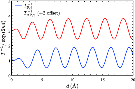
Figure 2 shows inverses of parallel and antiparallel transmittances, and , divided by the exponentially increasing factor . Here, we set (: lattice constant of MgO), which is the decaying wave number for the complex band of MgO calculated by the PWCOND code 2004Smogunov-PRB . We also used and (: lattice constant of bcc Fe) obtained by calculating the band structure of bcc Fe [Figs. 1(b) and 1(c)] with the aid of QUANTUM ESPRESSO 2009Giannozzi-JPCM . In both and , we can see a clear oscillation with a period of . From the values of and mentioned above, the period is estimated to be . These are consistent with the experimental fact that resistances in both the parallel and antiparallel magnetization states have oscillatory barrier thickness dependences with periods of 2007Matsumoto-APL ; 2022Scheike-APL ; 2023Scheike-APL . In addition, a finite phase difference between and can be seen in Fig. 2, which is essential for the occurrence of the TMR oscillation discussed below.
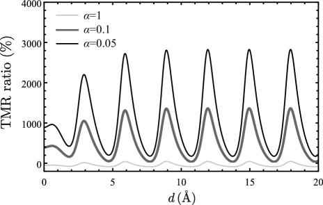
By using and , we calculated the TMR ratio given by
| (11) |
where is an adjustment parameter between and . Figure 3 shows barrier thickness dependences of the TMR ratio for different values of . For all the values of , the TMR ratio shows an oscillation with a period of similarly to and . The parameter is set to 1 in the usual definition of the TMR ratio. However, the TMR ratio takes negative values for , inconsistent with positive high TMR ratios observed in experiments. This is because the present analysis employs only the values of the Fermi momenta and the decaying wave number and does not consider detailed electronic structures of bcc Fe and MgO. If the electronic structures are taken into account by using the first-principles calculation 2001Butler-PRB ; 2001Mathon-PRB , values of are around one order of magnitude smaller than those of . Thus, we hereafter set for a better comparison with experimental values of the TMR ratio obtained at room temperature remark1 .
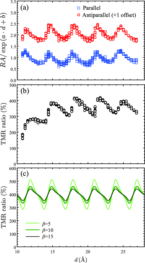
Finally, let us directly compare our calculation results with an experimentally observed TMR oscillation. To this aim, we fabricated an MTJ structure and measured magnetotransport properties. The experimental details are explained in the Supplemental Material. Figure 4(a) shows barrier thickness dependences of the resistance-area product () in the parallel and antiparallel magnetization states, where is a product of the resistance and the cross-sectional area of the MTJ. We show values of the divided by , where and were determined to be 5.48 (5.73) nm-1 and () in the parallel (antiparallel) magnetization state, respectively, from the fits using the exponential function. As seen in Fig. 4(a), the has an oscillatory dependence with a period of in both the parallel and antiparallel magnetization states. Since there is a finite phase difference in values between the parallel and antiparallel magnetization states, the TMR ratio has a similar oscillation as shown in Fig. 4(b). For a direct comparison with our experimental results, we introduced another parameter for non-oscillatory components remark2 and calculated the TMR ratio given by
| (12) |
where is fixed to 0.1 as mentioned above. Note here that our present theory focuses on the electronic state along the line just at because of its dominant contribution to the TMR effect. However, in actual experiments, electronic states around can also contribute to the transmission, which can justify the inclusion of in our expression. Figure 4(c) shows the calculated TMR ratios for different values of . The shape of the TMR oscillation is quite similar to that in our experimental results, which show a saw-tooth like oscillation remark3 . In addition, the TMR ratios calculated for are found to quantitatively agree with experimental values. Therefore, we conclude that the TMR ratio calculated by Eq. (12) can reproduce the experimental results not only qualitatively but also quantitatively.
In summary, we proposed a theory for explaining the universal oscillation of the TMR ratio called the “TMR oscillation.” Based on the fact that spin-flip scattering occurs near interfaces of MTJs, we took into account the superposition of the majority-spin and minority-spin wave functions with different Fermi momenta for the tunneling problem in Fe/MgO/Fe(001). We analytically calculated transmittances in the parallel and antiparallel magnetization states, from which the TMR ratio was obtained. It was found that the transmittances and the TMR ratio have oscillatory barrier thickness dependences with a period of , consistent with the experimental observations. According to our theory, the period of the TMR oscillation is determined by the difference of the Fermi momenta between the majority- and minority-spin states in the ferromagnetic electrode. Therefore, the period of is specific to bcc Fe used as electrodes. If MTJs with other ferromagnetic electrodes are successfully made, TMR oscillations with periods different from would be observed. We can also predict that a resistance oscillation cannot be observed in tunnel junctions with nonmagnetic electrodes, since the spin degree of freedom is essential for the resistance oscillation in our theory. We expect future experimental studies using a wider range of materials will provide further information for the TMR oscillation.
Acknowledgements.
The authors are grateful to S. Yuasa and H. Imamura for fruitful discussions. This work was supported by Grants-in-Aid for Scientific Research (Grant Nos. 22H04966, 23K03933, and 24H00408) and MEXT Program: Data Creation and Utilization-Type Material Research and Development Project (Grant No. JPMXP1122715503). MANA is supported by the World Premier International Research Center Initiative (WPI) of MEXT, Japan. The band structure calculation was performed on the Numerical Materials Simulator at NIMS.References
- (1) L. Esaki, Phys. Rev. 109, 603 (1958).
- (2) I. Giaever, Phys. Rev. Lett. 5, 147 (1960).
- (3) G. Binnig and H. Rohrer, Rev. Mod. Phys. 59, 615 (1987).
- (4) S. S. P. Parkin, C. Kaiser, A. Panchula, P. M. Rice, B. Hughes, M. Samant, and S.-H. Yang, Nat. Mater. 3, 862 (2004).
- (5) S. Yuasa, T. Nagahama, A. Fukushima, Y. Suzuki, and K. Ando, Nat. Mater. 3, 868 (2004).
- (6) R. Matsumoto, A. Fukushima, T. Nagahama, Y. Suzuki, K. Ando, and S. Yuasa, Appl. Phys. Lett. 90, 252506 (2007).
- (7) T. Scheike, Q. Xiang, Z. Wen, H. Sukegawa, T. Ohkubo, K. Hono, and S. Mitani, Appl. Phys. Lett. 118, 042411 (2021).
- (8) T. Scheike, Z. Wen, H. Sukegawa, and S. Mitani, Appl. Phys. Lett. 120, 032404 (2022).
- (9) T. Scheike, Z. Wen, H. Sukegawa, and S. Mitani, Appl. Phys. Lett. 122, 112404 (2023).
- (10) W. H. Butler, X.-G. Zhang, T. C. Schulthess, and J. M. MacLaren, Phys. Rev. B 63, 054416 (2001).
- (11) J. Mathon and A. Umerski, Phys. Rev. B 63, 220403(R) (2001).
- (12) C. Heiliger, P. Zahn, B. Y. Yavorsky, and I. Mertig, Phys. Rev. B 77, 224407 (2008).
- (13) X.-G. Zhang, Yan Wang, and X. F. Han, Phys. Rev. B 77, 144431 (2008).
- (14) G. Autès, J. Mathon, and A. Umerski, Phys. Rev. B 84, 134404 (2011).
- (15) P. Mavropoulos, M. Lezaic, and S. Blügel, Phys. Rev. B 72, 174428 (2005).
- (16) Y. Miura, K. Abe, and M. Shirai, Phys. Rev. B 83, 214411 (2011).
- (17) K. Masuda, T. Tadano, and Y. Miura, Phys. Rev. B 104, L180403 (2021).
- (18) These are expressed as , , , and . The continuation conditions including different effective masses have been used for discussing tunneling currents in - junctions or metal/oxide/semimetal tunnel junctions 1966BenDaniel-PR .
- (19) D. J. BenDaniel and C. B. Duke, Phys. Rev. 152, 683 (1966).
- (20) If we set , Eq. (4) coincides with Eq. (3) in Ref. 1997MacLaren-PRB , where different effective masses are not considered.
- (21) J. M. MacLaren, X.-G. Zhang, and W. H. Butler, Phys. Rev. B 56, 11827 (1997).
- (22) Y. Miura, S. Muramoto, K. Abe, and M. Shirai, Phys. Rev. B 86, 024426 (2012).
- (23) K. Masuda and Y. Miura, Jpn. J. Appl. Phys. 56, 020306 (2017).
- (24) K. Masuda and Y. Miura, Phys. Rev. B 96, 054428 (2017).
- (25) We also considered a similar superposition of wave functions in the incident and reflection waves. This additional analysis clarified that these do not affect the oscillatory behavior of the transmittance given by the superposition in the transmission wave. Thus, we omit these effects for simplicity.
- (26) We used the same continuation conditions as mentioned in Ref. remark_conti-condition .
- (27) This is because can be calculated by using instead of Eq. (7).
- (28) A. Smogunov, A. Dal Corso, and E. Tosatti, Phys. Rev. B 70, 045417 (2004).
- (29) P. Giannozzi, S. Baroni, N. Bonini, M. Calandra, R. Car, C. Cavazzoni, D. Ceresoli, G. L. Chiarotti, M. Cococcioni, I. Dabo, A. Dal Corso, S. de Gironcoli, S. Fabris, G. Fratesi, R. Gebauer, U. Gerstmann, C. Gougoussis, A. Kokalj, M. Lazzeri, and L. Martin-Samos et al., J. Phys.: Condens. Matter 21, 395502 (2009).
- (30) TMR ratios at low temperature are more than twice as high as those at room temperature and can be reproduced by using a smaller value of .
- (31) The non-oscillatory components decrease exponentially as the barrier thickness increases similarly to the oscillatory component, which is expressed by .
- (32) Experimentally, the shape of the TMR oscillation is different for different samples. Actually, Mg4AlOx-based MTJs have saw-tooth like shapes 2022Scheike-APL similarly to our present results, while MgO-based MTJs have sine-like shapes 2021Scheike-APL ; 2023Scheike-APL . These different shapes can be reproduced by tuning the parameters in our model.