High-fidelity single-spin shuttling in silicon
Abstract
The computational power and fault-tolerance of future large-scale quantum processors derive in large part from the connectivity between the qubits. One approach to increase connectivity is to engineer qubit-qubit interactions at a distance [1, 2]. Alternatively, the connectivity can be increased by physically displacing the qubits. This has been explored in trapped-ion experiments [3, 4] and using neutral atoms trapped with optical tweezers [5, 6]. For semiconductor spin qubits, several studies have investigated spin coherent shuttling of individual electrons [7, 8, 9, 10, 11, 12, 13, 14, 15, 16], but high-fidelity transport over extended distances remains to be demonstrated. Here we report shuttling of an electron inside an isotopically purified Si/SiGe heterostructure using electric gate potentials. First, we form static quantum dots, and study how spin coherence decays as we repeatedly move a single electron between up to five dots. Next, we create a traveling wave potential to transport an electron in a moving quantum dot. This second method shows substantially better spin coherence than the first. It allows us to displace an electron over an effective distance of in under 200 ns with an average fidelity of . These results will guide future efforts to realize large-scale semiconductor quantum processors, making use of electron shuttling both within and between qubit arrays [17, 18, 19, 20, 21, 22].
I Introduction
Quantum computing shows promise for tackling computationally challenging problems beyond the capabilities of classical computers. To harness the full potential of quantum computation, errors will need to be corrected faster than they appear. The requirements for fault-tolerant quantum computation in terms of redundancy and error rates are generally eased when the connectivity between the qubits is stronger [23, 24]. Even then, the needed redundancy will quickly bring the number of qubits into the millions. Given the challenges in realizing large-scale monolithic quantum registers, approaches based on networks of spatially separated qubit registers that are connected by quantum links have gained traction.
Among the numerous quantum computing platforms, gate-defined semiconductor spin qubits [25] have garnered significant attention. Recent advances in this field showcase extended spin coherence [26], high-fidelity single- [27, 28, 29] and two-qubit [30, 31, 32, 33] gates, high-temperature operation [34, 35], and universal control over up to six qubits [36]. Moreover, spin qubits are an attractive choice for densely packed quantum processors because of their compatibility with existing semiconductor fabrication techniques [37, 38] and pitch of about 100 nm.
Whereas the conventional two-qubit gate relies on the exchange interaction between spins in adjacent quantum dots, several avenues for increasing the connectivity between distant spin qubits on the same chip have been proposed and explored. Much effort has gone into engineering hybrid devices where superconducting resonators are used to couple electron or hole spins in quantum dots. This culminated in the recent observation of iSWAP oscillations between two spins separated by a few hundred micrometers [2]. A promising alternative for distances of up to about ten micrometers consists in transporting (shuttling) spins across the chip, which can increase the connectivity within a qubit register and form a coherent link between qubit registers [17, 18, 19, 20, 21, 22].
Two distinct procedures for spin shuttling exist, referred to as bucket-brigade and conveyor-mode. Bucket-brigade (BB) shuttling involves transporting a spin through an array of quantum dots by successively adjusting their electrochemical potentials. Successful charge transfer was realized across nine dots [39] and spin-flip probabilities per hop below 0.01 were observed in both GaAs [40] and Si/SiGe quantum dot arrays [41, 12]. Preservation of the spin phase was probed qualitatively in GaAs quantum dots [10, 9] and quantitatively in a silicon double quantum dot, with phase-flip probabilities of 1.8 [11] and 0.19 [12] per hop. Additionally, it was shown in Ge quantum dots that diabatic BB shuttling in the presence of spin-orbit interaction can be used to generate single-qubit gates with fidelities of 99.97 [42]. Conveyor-mode (CV) shuttling is a technique in which a traveling wave potential transports the spin inside a moving quantum dot. The traveling wave potential can be generated by a surface acoustic wave of by phase-shifted sinusoidal signals applied to successive gate electrodes. Also with conveyor-mode shuttling, charge transfer was demonstrated along channels of on the order of long [43, 44, 45]. Coherent spin transfer was studied by moving one of two electrons prepared in a spin singlet state [16, 15]. However, the relative performance of the two methods has not been compared directly so far. More importantly, coherent spin transfer over extended distances that is both fast and high-fidelity remains to be demonstrated.
In this work, we quantitatively investigate the phase flip probability when repeatedly moving an electron back and forth through a linear device in isotopically purified Si/SiGe, using Ramsey-style and Hahn-echo-style measurements. We compare the performance of bucket-brigade and conveyor-mode shuttling, including a novel conveyor-mode implementation that introduces sine waves with two frequencies instead of one, and study the performance as a function of the driving amplitude and shuttling speed. Finally, we execute interleaved randomized benchmarking (IRB) to quantify the shuttling fidelity for a cumulative displacement of ten micrometers through the device.
II Results
II.1 Device and characterization
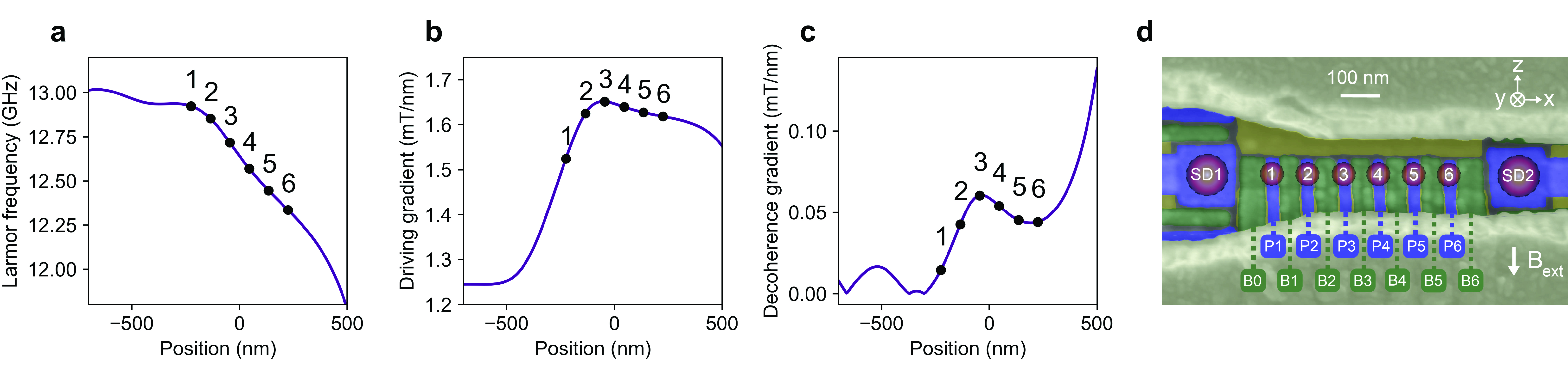
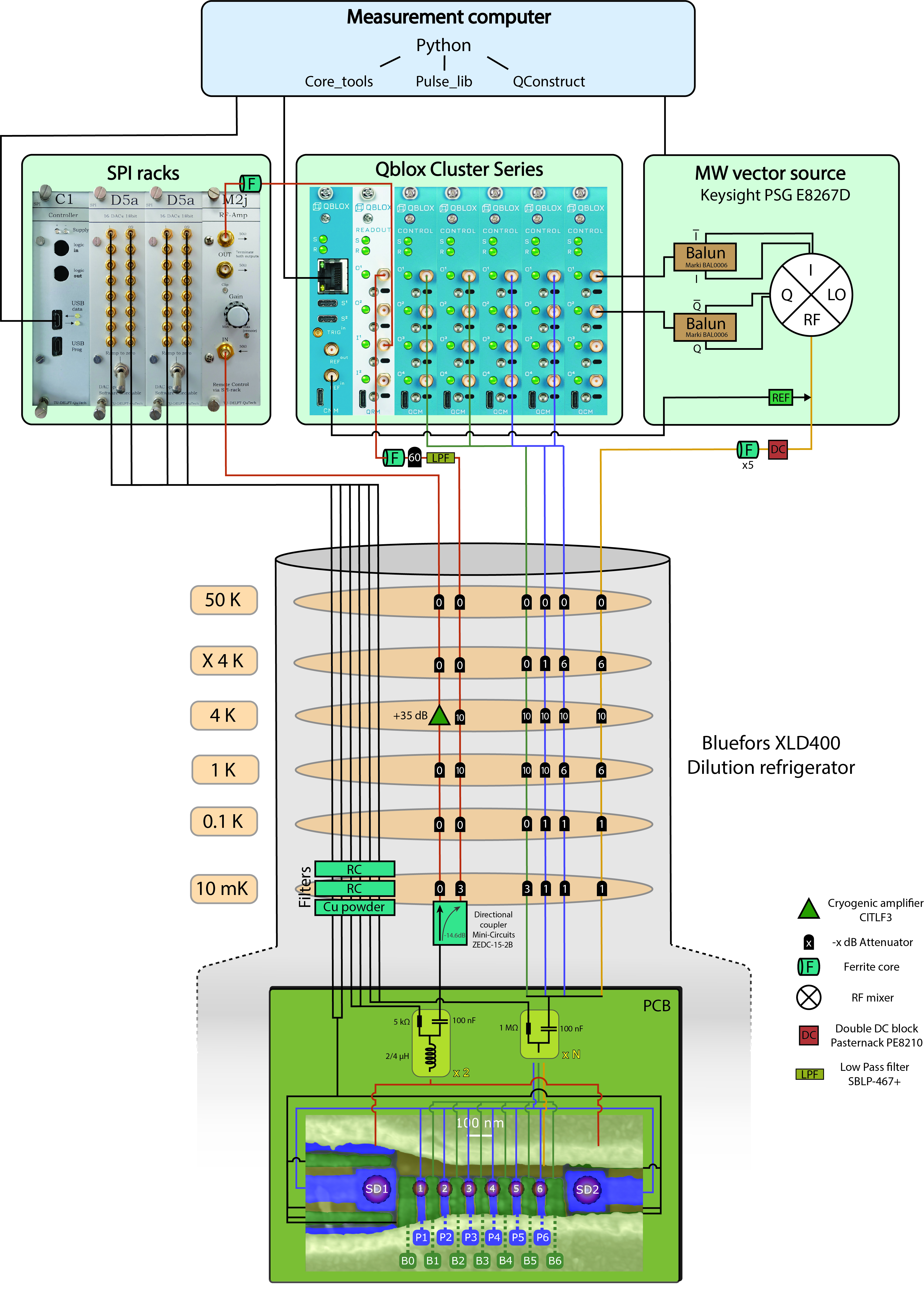
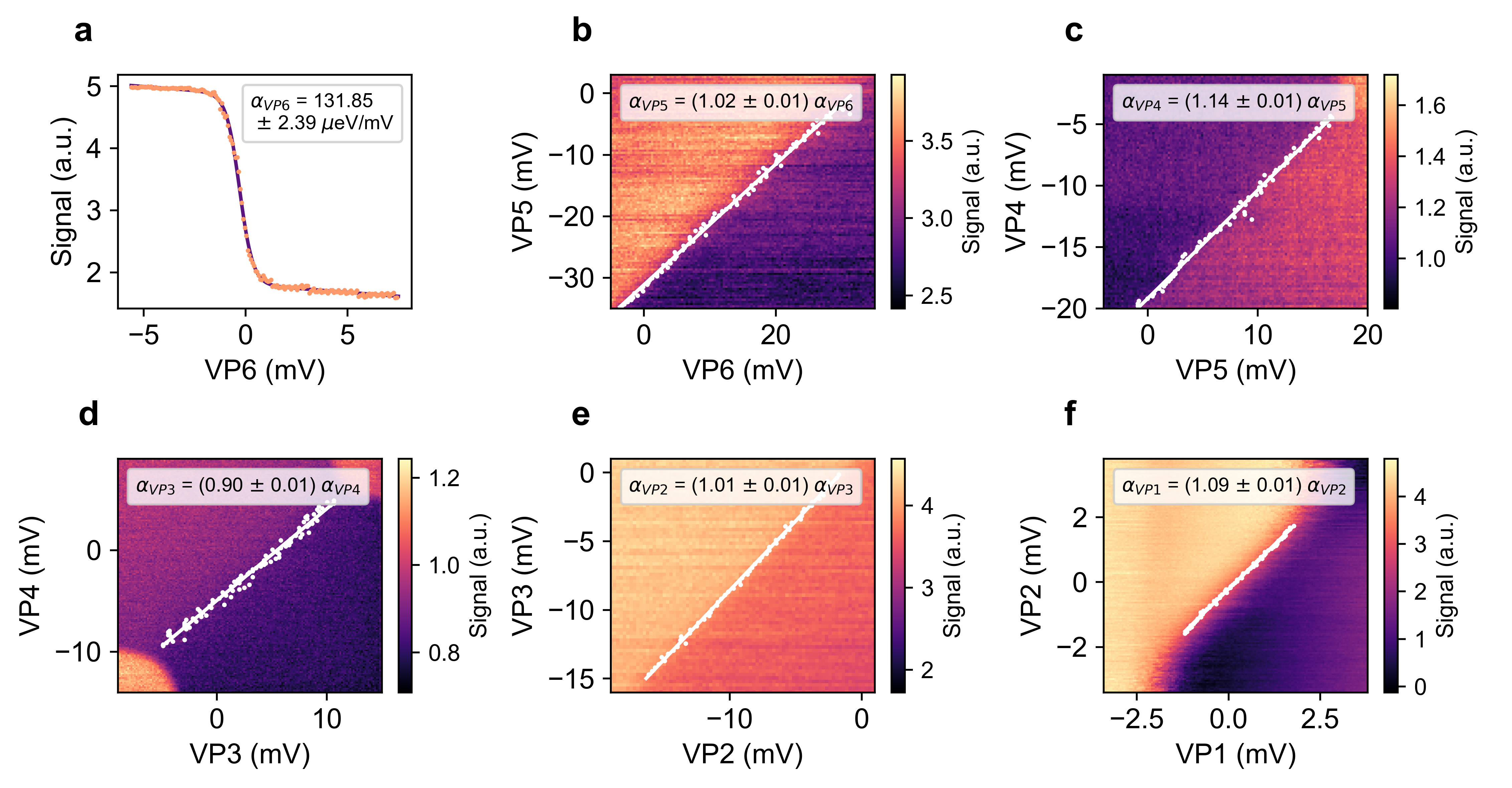
The device is fabricated on an isotopically-purified 28Si/SiGe heterostructure featuring a quantum well, as studied in [46], hosting a linear array of six quantum dots (Fig. 1a). The confinement potentials are defined by three layers of Ti:Pd gates separated by \chAl2O3, serving as screening, plunger (P) and barrier (B) gates, respectively. Sensing dots are placed at the ends of the linear array to facilitate charge sensing and to act as electron reservoirs. A cobalt micromagnet is deposited on top of the gate electrodes. Its stray field enables electric-dipole spin resonance (EDSR) for single-qubit rotations [47] and separates the spin resonance frequencies for electrons in different dots. An external magnetic field of is applied in the plane of the quantum well and all experiments are performed in a dilution refrigerator set to a temperature of [34].
We operate at the (3,1)-(4,0) charge transition of dots 1 and 2, creating a sizable readout window for parity Pauli-spin-blockade [48, 36]. Initialization of two electron spins is done by ramping from the (4,0) to the (3,1) charge state, subsequently performing parity read out of the spin states and post-selecting the single-shot runs with either the parallel or anti-parallel measurement outcomes.
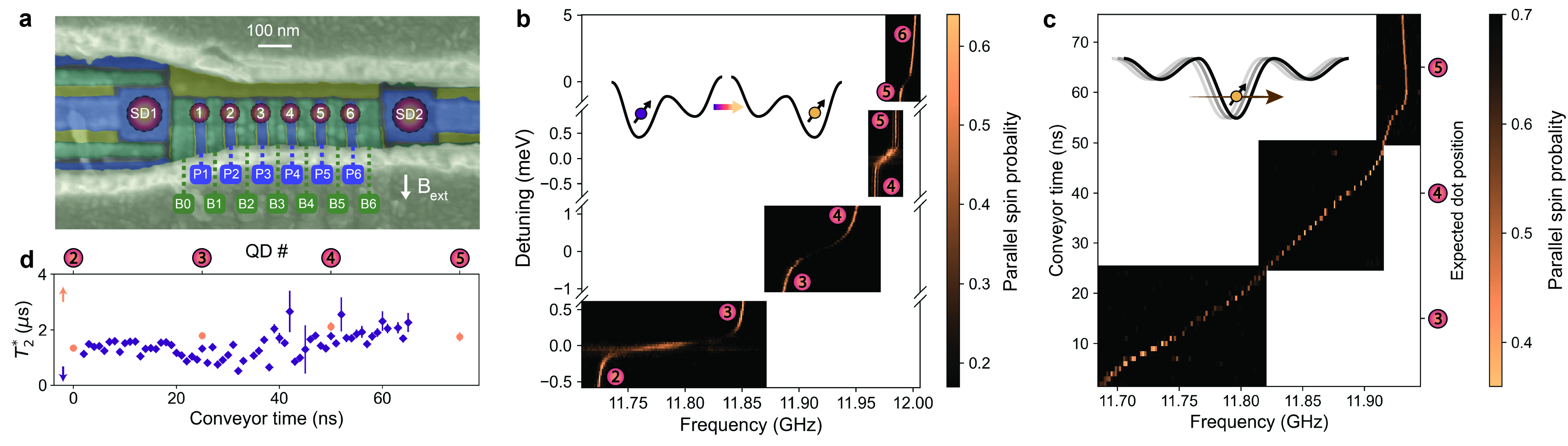
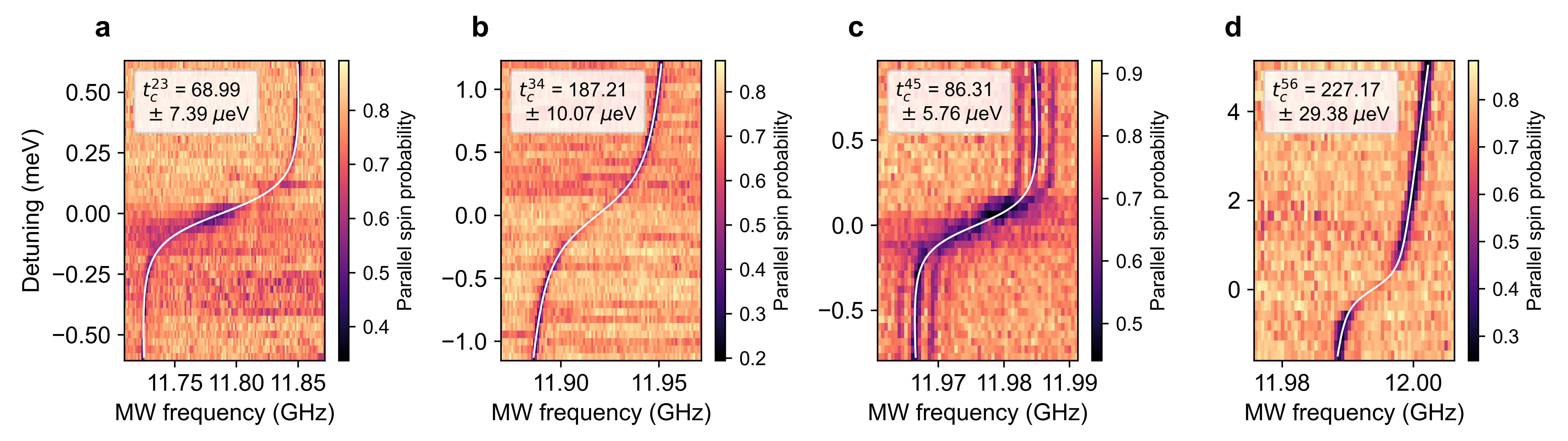
All other quantum dots are emptied in order to investigate coherent spin shuttling through the array. For bucket-brigade, we pulse not only the electrochemical potentials but also raise the interdot barrier gate voltages one after the other to temporarily establish a large interdot tunnel coupling (between 17 and 55 GHz, see Supplementary Information). A large tunnel coupling is required for a rapid transfer between dots while maintaining adiabaticity [9, 10, 40]. Figure 1b shows how the qubit resonance frequency abruptly shifts as an electron is displaced between neighbouring dots. For conveyor-mode shuttling we employ a number of phase-shifted sine signals applied to the plunger and barrier gates. The resulting traveling-wave potential transports the electron within a single potential minimum. This technique allows continuous control of the electron position along the array. Figure 1c shows a continuous trend of the resonance frequency (albeit different than expected, see Supplementary Information).
The local spin dephasing time can be probed for an electron in a static conveyor potential minimum as well as in any of the predefined dots (Fig. 1d). In both cases, microwave driving is applied when the spin is in dot 2, while the idling time is spent in either a predefined dot or in a static conveyor potential minimum. shows an increasing trend towards dot 5, where the local magnetic field gradient from the micromagnet is weaker. Presumably charge noise leads to dephasing as it modulates the electron position in the gradient magnetic field, with additional dephasing contributions from residual hyperfine noise. We note that the dephasing times in the predefined dots are in general slightly longer than those in the conveyor minimum, indicating a tighter confinement hence reduced electrical susceptibility in the predefined dots.
II.2 Bucket-brigade operation
We study the bucket-brigade shuttling performance via Ramsey- and Hahn-echo-style measurements. We first investigate shuttling between adjacent dots (similar to [11, 12]) and next perform shuttling across multiple quantum dots.
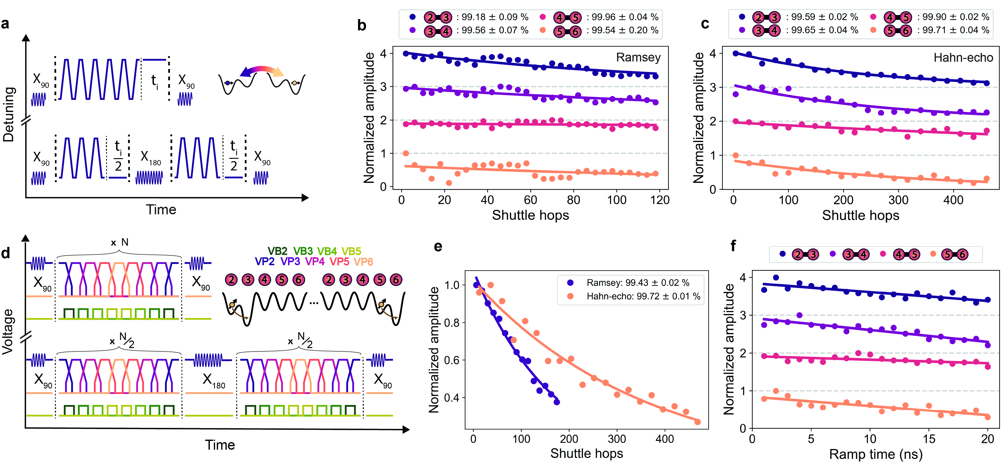
After initializing the reference spin in dot 1 and the spin in dot 2 in a parallel state, an gate is applied to the spin in dot 2. Next this spin is transported to the target double dot after which it is repeatedly transferred back and forth between the two sites (with a ramp time of 2 ns and a wait time of 1 ns in each dot, see the pulse schematics in Figure 2a). The number of shuttle hops is varied while the idle time at the end of the shuttle sequence is adjusted, keeping the total sequence time constant. This allows to isolate the impact of hopping on the spin coherence. In the Hahn-echo measurements, a refocusing gate is applied in dot 2 after half the number of hops. After shuttling, a second rotation is applied in dot 2 before the spin state is measured using parity readout.
Figures 2b and 2c show the decaying amplitude of Ramsey and Hahn-echo fringes, respectively, with increasing number of shuttle hops. The fringes are measured in a rotating frame which is detuned from the qubit frequency by about 30 MHz. For all four double dot pairs, the decay is fitted to an exponential function, yielding return probabilities above 99% per hop (dividing the total error by the number of hops), and in some cases up to 99.9%. We here define return probability as the normalized probability for the spin to arrive in the expected final state, excluding initialization and measurement errors. The return probability is higher in double dots with a smaller Zeeman splitting difference (see Fig.1b), which agrees with numerical simulations (see Supplementary Information). Double dot 5-6 does not follow this trend, which is possibly related to the comparatively large voltage needed on gate B5.
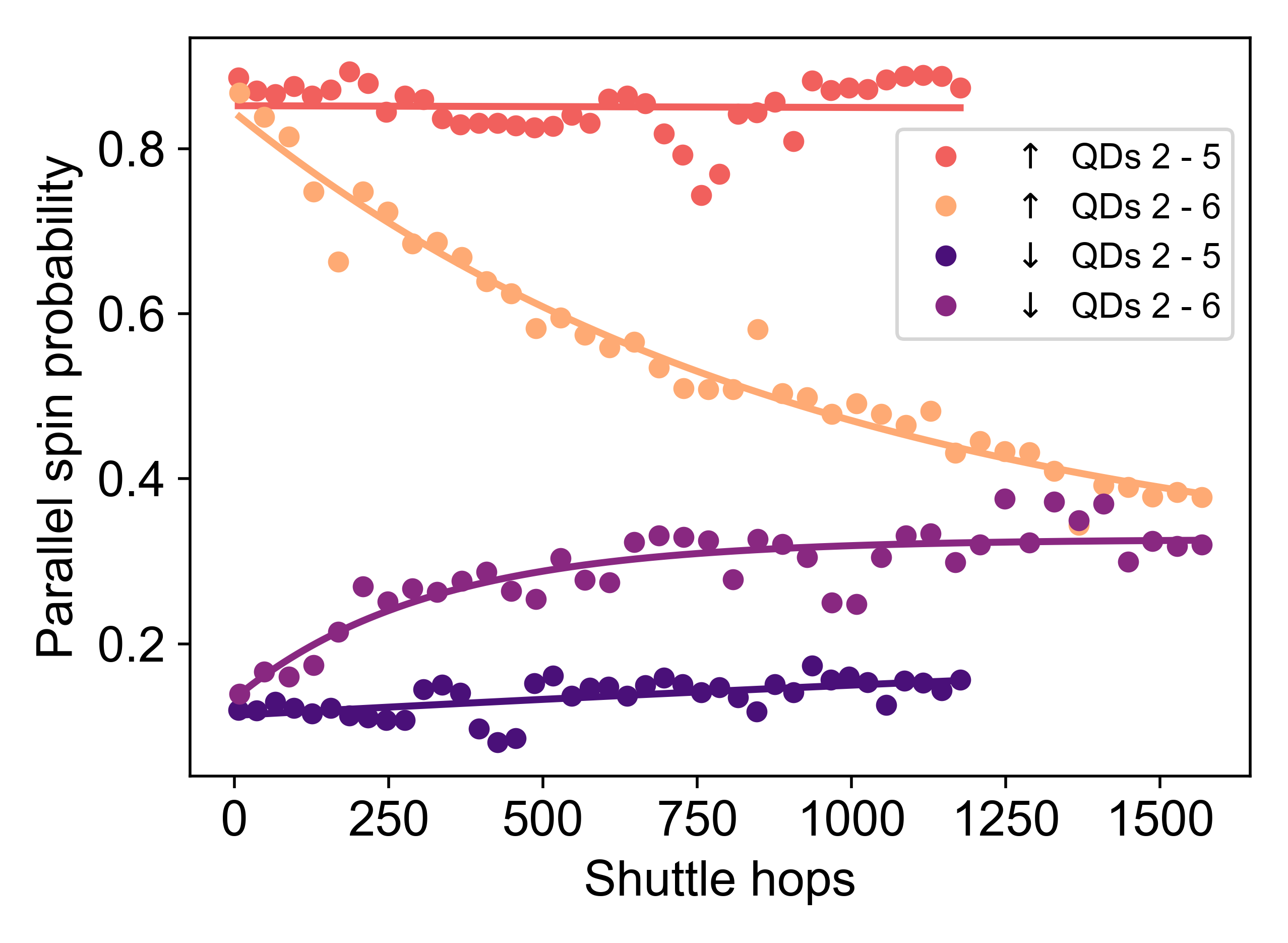
Next we evaluate spin coherence during sequential shuttling through the entire array. We pulse both the interdot detuning and the tunnel coupling between the successive double dots in turn, in order to minimize charge leakage (Fig. 2d). Figure 2e shows the decaying amplitude of Ramsey and Hahn-echo fringes, respectively, with increasing number of shuttle hops between dot 2 to dot 5 (BB shuttling works best between these dots, see Supplementary Information). In contrast to the shuttling benchmark in double dots (Figs. 2b and c), we vary the number of hops without additional idle times at the end of the shuttling sequence. This means spin coherence lost during the shuttling process or while idling in individual dots cannot be distinguished. However, this approach does reveal how spin coherence is affected overall when shuttling under realistic conditions across many quantum dots. We obtain an average return probability per hop of 99.43 0.02 % with the Ramsey protocol and of 99.72 0.01 % with the Hahn-echo protocol.
The spin dephasing time extracted from the BB shuttling measurements in Figure 2e is , compared to an average of in the static dots. This indicates that the act of hopping between dots increases the phase flip probability. As stated in other works [11, 49, 13], charge noise couples more strongly to the qubit in the low detuning regime of each double quantum dot, where the resonance frequency is highly sensitive to detuning fluctuations (see Fig. 1b). Phase flips from hopping can also occur in case the charge transitions are not perfectly adiabatic with respect to the tunnel couplings. Small uncertainties in the timing of charge transfer then lead to dephasing due to the Larmor frequency difference between the quantum dots. Such diabatic transitions can in principle result either from the high-frequency components of the voltage ramp, or from rapid electric field fluctuations arising from charge noise. Figure 2f shows that the phase flip errors monotonously decrease with decreasing ramp time down to 2 ns. Furthermore, the loss of phase coherence increases with the Zeeman splitting difference. These observations are consistent both with enhanced dephasing halfway the interdot transition (see the simulations in the Supplementary Information) and with diabatic transitions from rapid electric field fluctuations as the phase flip mechanism. Contrary to these trends, we systematically observe larger phase flip probabilities with 1 ns ramps than with 2 ns ramps. Presumably the 1 ns ramp time in combination with the 1 ns wait time between ramps does not allow the pulse to reach full amplitude given the waveform generator bandwidth.
II.3 Conveyor-mode operation
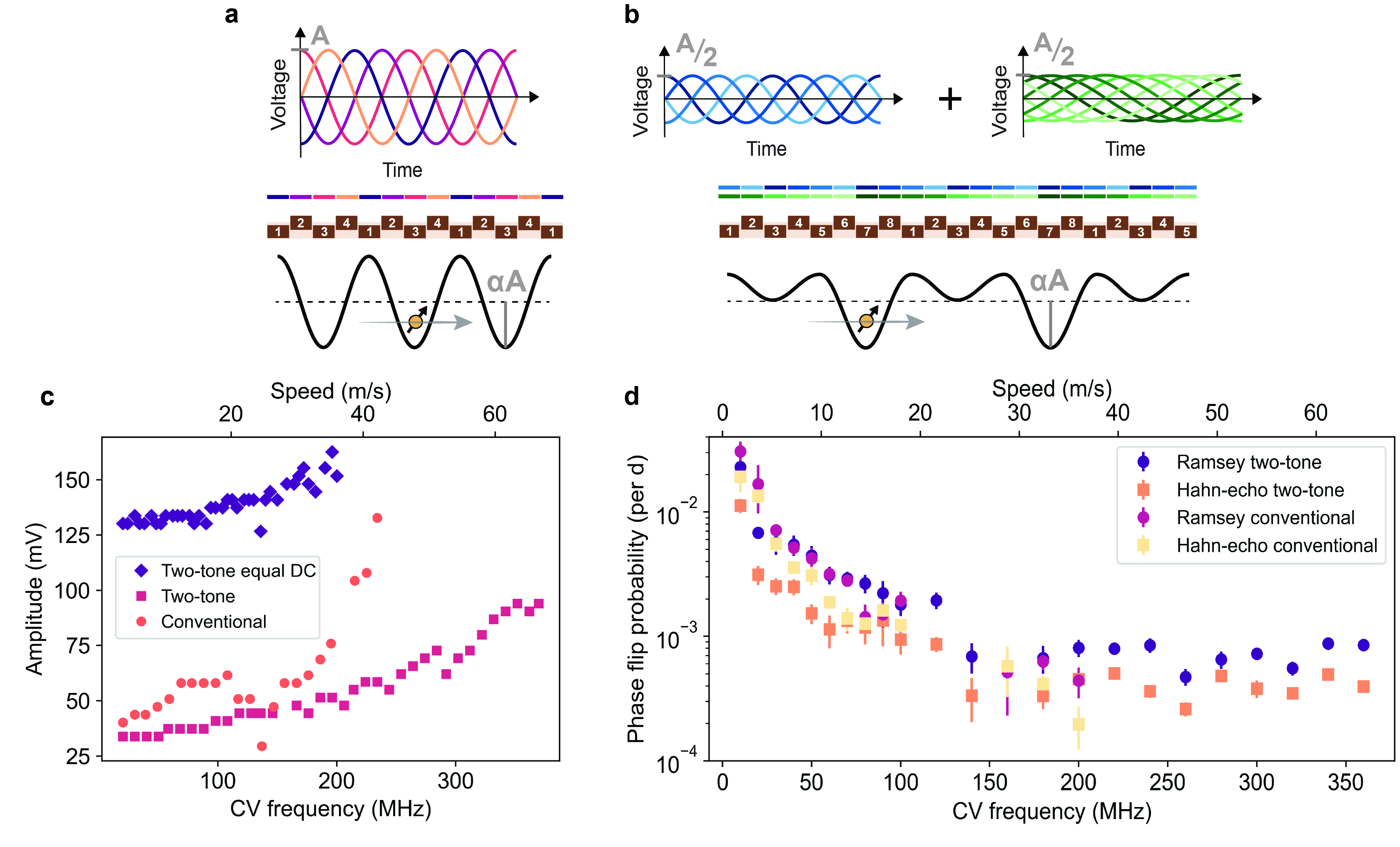
Turning to conveyor-mode shuttling [7, 50, 15], the traditional approach makes use of four phase-shifted voltage signals applied to a set of gate electrodes, with the voltage
| (1) |
applied to gate , where and a phase offset that determines the initial position of the potential minima. Here, represents a DC voltage offset and is the conveyor frequency. In most measurements shown below, we individually adjust the DC voltage applied to each gate in order to compensate for disorder in the background potential. The voltage signals and resulting traveling potential wave are illustrated in Figure 3a.
We additionally propose and assess a novel two-tone conveyor approach with voltage signals given by
| (2) |
This conveyor incorporates a second sine wave with exactly half the original conveyor frequency and . While requiring twice the number of distinct control signals compared to the conventional conveyor, a significant advantage in the shape of the traveling potential wave (Figure 3b) is achieved. Destructive interference at every second potential minimum strongly suppresses charge leakage to neighboring moving dots during shuttling. This is especially relevant in the presence of disorder in the background potential landscape. In Eqs. 1 and 2, we have assumed that equal amplitude sine signals are applied to all gates. Given that the barrier gates are less well coupled to the channel than the plunger gates, the amplitude applied to the barrier gates was 1.4 times that applied to the plunger gates, a ratio which we found works well (all values below refer to the plunger gate amplitudes). We note that also the two tones could be applied with different amplitudes.
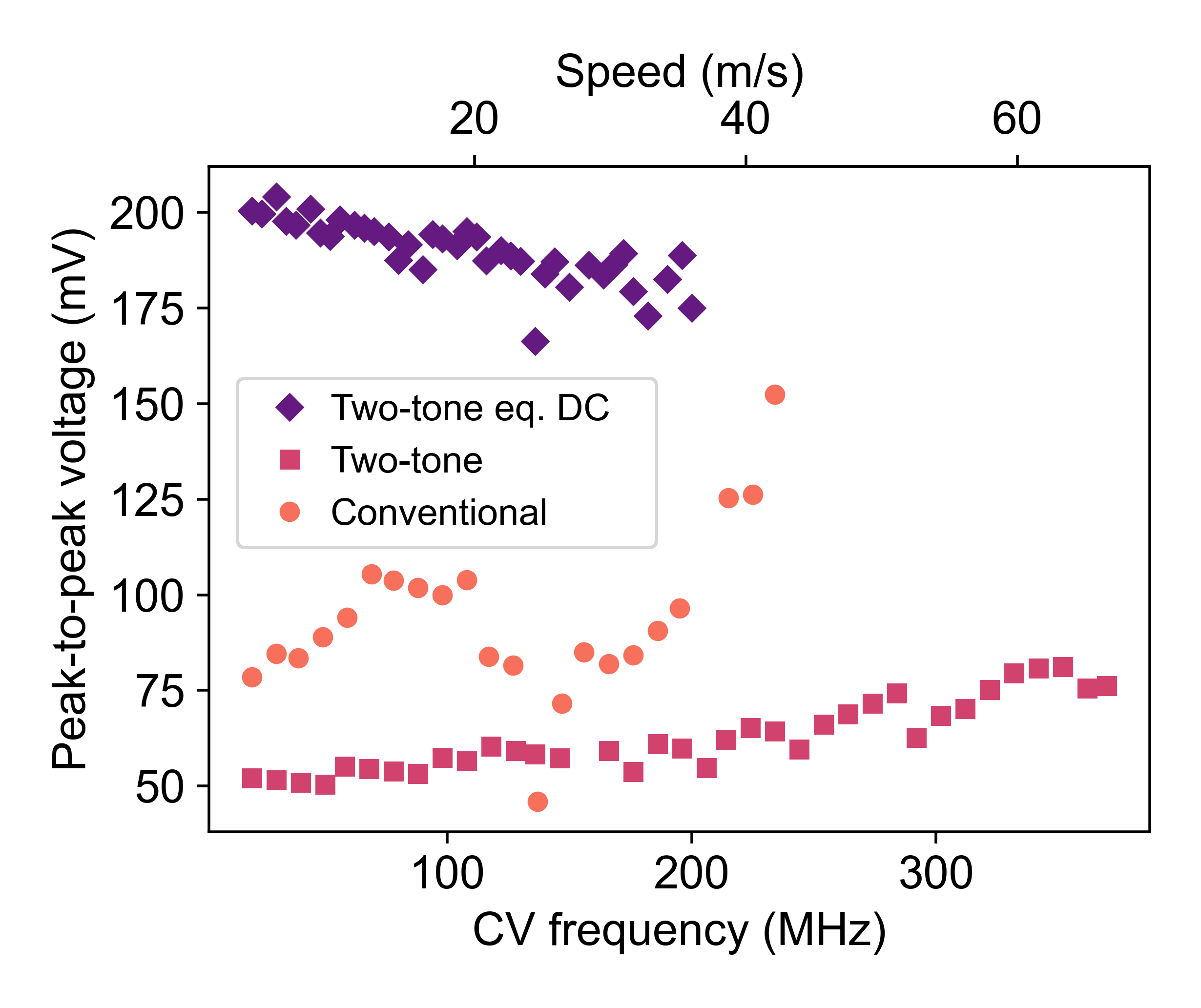
To determine the amplitude required for successful charge transfer by the conveyor, we shuttle a single spin from below gate P2 to close to below gate P5, apply an gate, and shuttle back. We then identify the minimal conveyor amplitude for which the spin flip from the gate is detected at readout, indicating successful charge transfer (the transition typically occurs within a few mV). Figure 3c shows the minimal amplitude as a function of the main conveyor frequency, where we observe that he conventional conveyor necessitates a higher amplitude than the two-tone conveyor. The data suggests that even faster transport would be feasible, especially for the two-tone conveyor (the shuttling speed was limited by the output filter of the control hardware). For comparison, we also show the minimum amplitude for the two-tone conveyor when the same DC voltage is applied to all plunger gates, and another fixed DC voltage is applied to all barrier gates [50, 15, 45]. Operating a conveyor with equal DC voltages applied to all gates would reduce the overhead involved in operating long-distance shuttling channels. We see that even though the non-uniformity in the background potential landscape is no longer compensated for by the local DC voltages, we can still successfully displace charges using the conveyor, albeit requiring a higher conveyor amplitude.
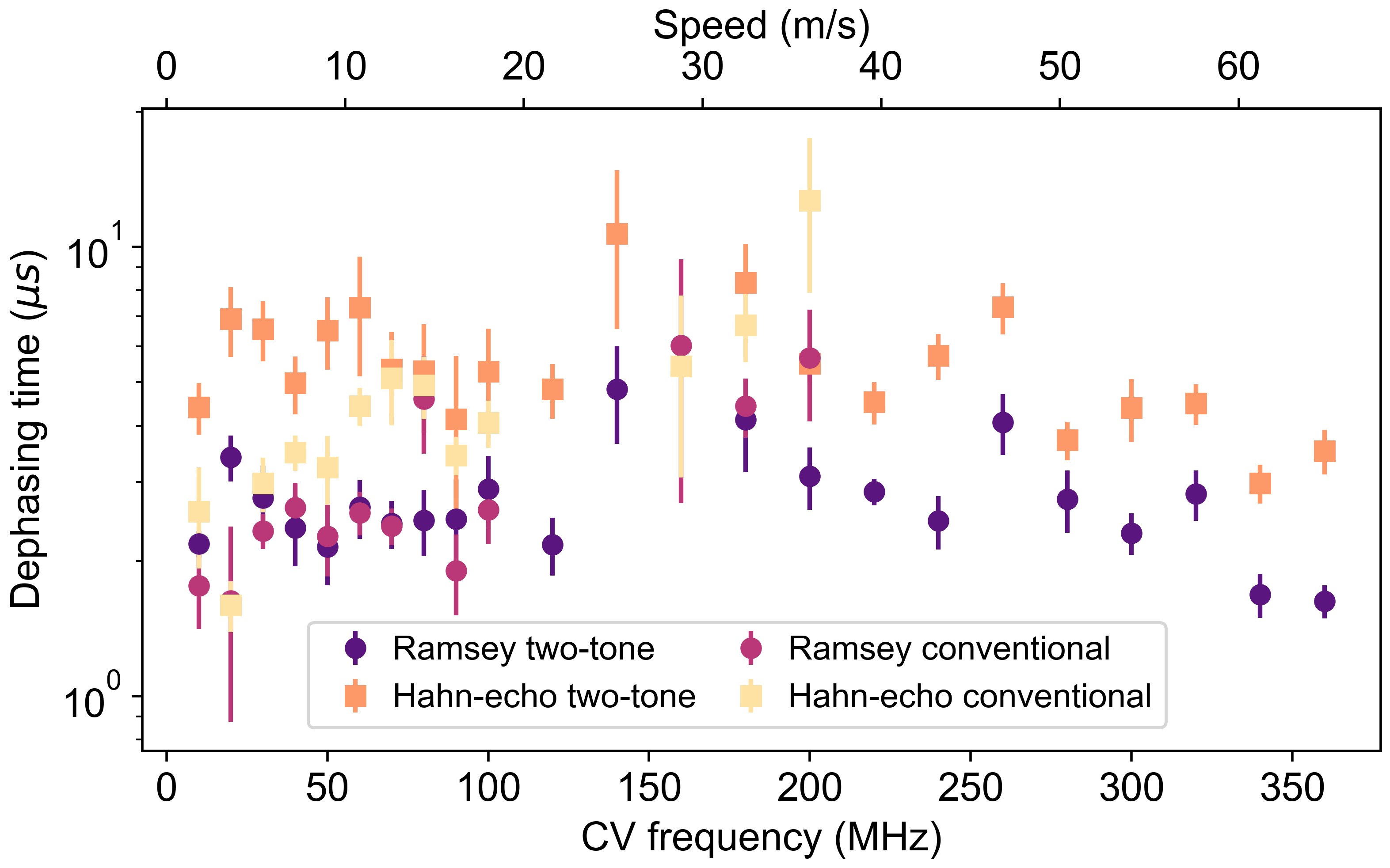
Similar to bucket-brigade shuttling, we characterize coherent spin transport in conveyor-mode by recording the return probability in Ramsey- and Hahn-echo-style sequences. Figure 3d shows the phase-flip probability, defined per plunger-to-plunger distance to allow comparison with BB, for both conveyor types. Initially the probability decreases with increasing speed. In general, faster transfer means the spin has less time to dephase while it is transported in the moving dot. Above 150 MHz, the measured phase-flip probability does not keep decreasing but saturates, for reasons that are not fully understood. The Ramsey phase flip probabilities are similar between the conventional and two-tone conveyor, whereas the echo sequences show better results for the two-tone version. Importantly, the two-tone case allows for significantly higher speeds with modest conveyor amplitudes (see Fig. 3c). Even though the observed spin-flip probabilities level off above 150 MHz, faster shuttling is still advantageous in future scenarios where a subset of qubits is subject to decoherence while others are shuttled.
The data pertaining dephasing in a moving conveyor is well-fitted to a single exponential, indicating high-frequency components in the noise experienced by the spin. For the static (two-tone) conveyor, the decay is close to Gaussian, pointing at low-frequency noise dominating the decay. This suggests that the exponential decay in a moving conveyor results primarily from moving through a spatially varying but quasi-static noise environment. Moreover, the extracted (exponential) dephasing time for both the conventional and two-tone conveyor during shuttling is longer than the (Gaussian) decay time in the static two-tone conveyor case in Figure 1d (see Supplementary Information). This indicates that shuttling in conveyor mode does not suffer from important additional dephasing channels and in fact may benefit from motional narrowing effects [7]. We note there is no clear dependence of on conveyor speed, which would suggest that the slowest conveyors used already fully benefit from motional narrowing.
II.4 Shuttling fidelity
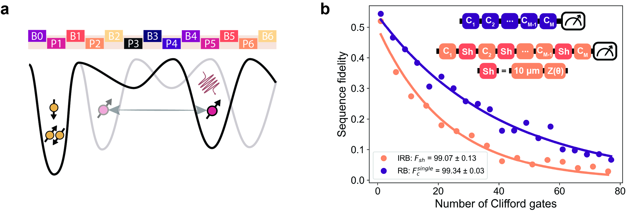
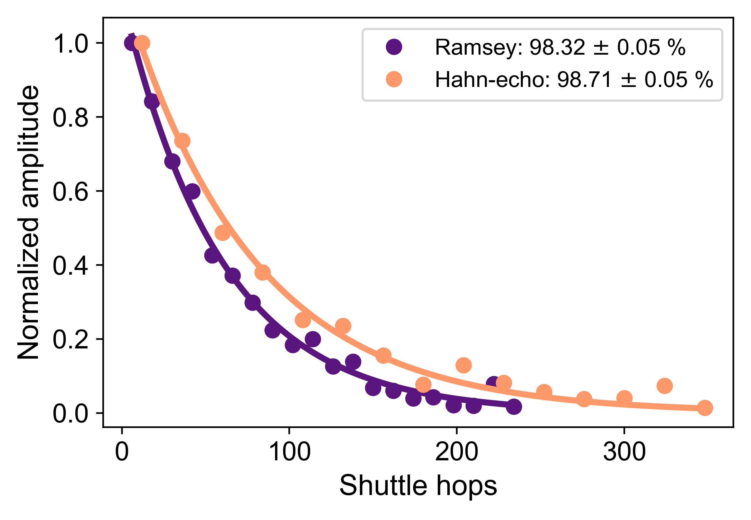
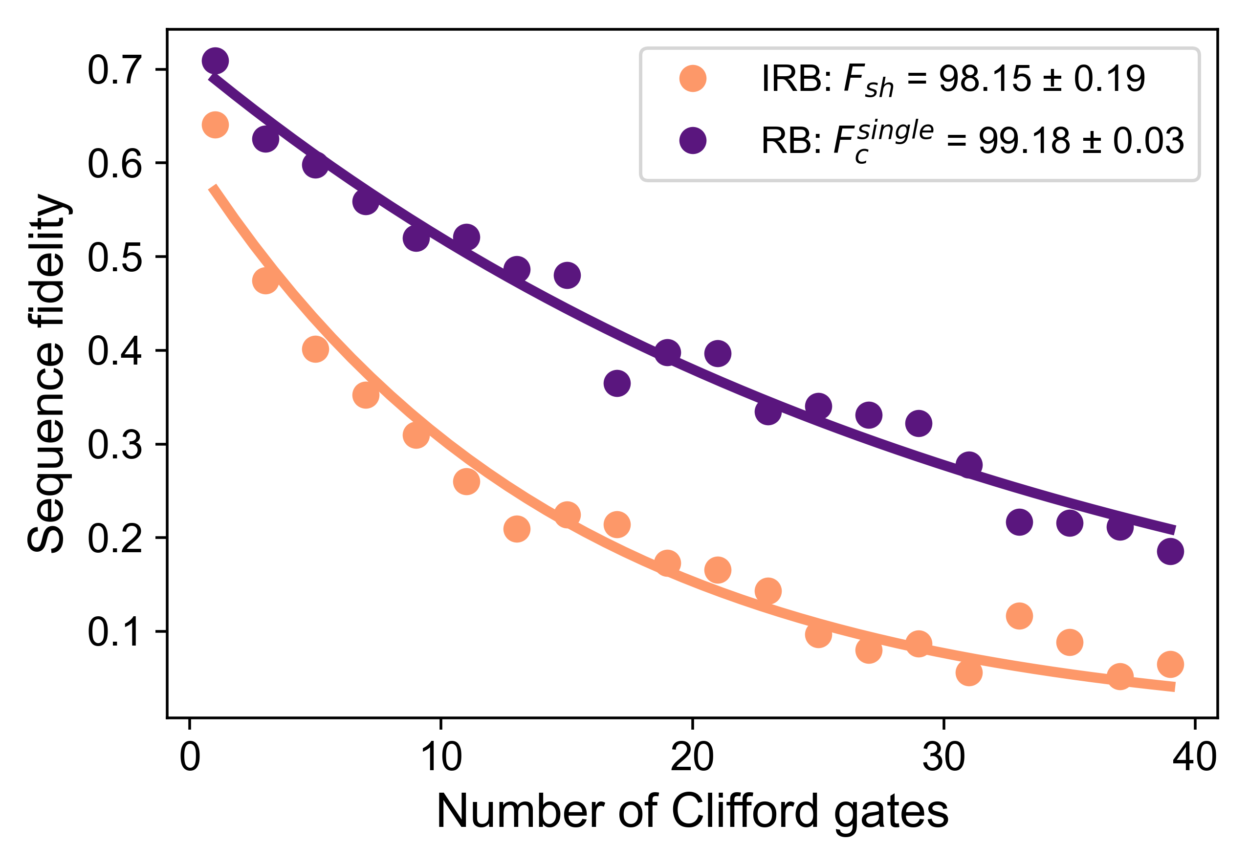
Finally, we characterize the shuttling fidelity of the high-speed two-tone conveyor by employing randomized benchmarking (RB). Figure 4a shows a schematic of the experiment. The spin is initialized in dot 2, then the conveyor potential is switched on and the electron is shuttled to below gate P5, where we execute Clifford operations using EDSR with the electron in the static conveyor minimum. To benchmark the shuttling fidelity, we compared the decay from a standard RB sequence with that of an interleaved RB sequence. We interleave repeated conveyor shuttling operations, roughly between gates P2 and P5, followed by a virtual Z operation that ensures the total operation (ideally) corresponds to the identity gate. Figure 4b shows the results for both the reference and interleaved RB sequence. We obtain a single-qubit gate fidelity of 99.34 0.03 and a shuttling fidelity of 99.07 0.13 for shuttling over a distance of .
Our analysis indicates that the conveyor shuttling fidelity is mainly limited by the ratio between the shuttling time and the static . After completion of the shuttling measurements, we found that up to twice longer values are obtained with the magnet in persistent mode, decreasing external field fluctuations and suggesting even higher spin shuttling fidelities are feasible in this sample. Additional improvements in the coherence time can be achieved by reducing charge noise and minimizing magnetic field gradients. Remarkably, the obtained already corresponds to a shuttle fidelity of 99.99 over a plunger-to-plunger distance, and the fidelity decays by after about , if we simply extrapolate.
III Conclusion
This work demonstrates for the first time coherent bucket-brigade shuttling in silicon across multiple dots. We obtain phase flip probabilities below 0.3% per hop when shuttling back and forth through the array. Conveyor-mode shuttling, using both conventional four-phase and novel two-tone conveyors, exhibits stable and highly coherent spin transport, with phase flip probabilities about one order of magnitude lower than our best BB results for a comparable distance. Using a two-tone conveyor, we are able to shuttle an electron back and forth over a cumulative distance of in less than and with a fidelity of 99%.
In this first comparative investigation of shuttling methods, we find that conveyor-mode shuttling allows faster spin transfer with a higher fidelity, limited by the inherent dephasing in the device. It avoids sequential adiabatic interdot crossings and repeated charge delocalization intrinsic to bucket-brigade shuttling. For successful conveyor-mode operation, we must ensure the electron does not escape from the traveling potential minimum, which can be especially challenging in the presence of disorder. With only a limited increase in control parameters, the two-tone conveyor reduces this escape probability and we find it allows higher shuttling speeds with lower drive amplitudes.
We note that future devices would likely not utilize a micromagnet on top of the shuttling channel, which could lead to even higher shuttling fidelities as the Zeeman splitting gradients will be orders of magnitude smaller. Moreover, one can encode the qubit in the - subspace and shuttle both electrons sequentially to further protect the shuttled information against quasi-static noise [17]. However, whereas the valley splitting in this device is estimated to be above 170 eV (see Supplementary Information), the possibility of encountering local regions with low valley splitting increases for longer quantum links [51]. This would require to (locally) slow down the conveyor [7] in order to avoid detrimental valley excitations, which would degrade the shuttling fidelity. Furthermore, we note that the best results are obtained when tweaking the individual DC gate voltages, which ideally is to be avoided in future implementations, requiring a lower level of background potential disorder [52].
In conclusion, this study demonstrates the viability of high-fidelity quantum interconnects between both local and distant spin qubits. These results will provide direction to the design and implementation of large-scale fault-tolerant architectures based on semiconductor spin qubits.
Acknowledgments
We wish to thank S.G.J. Philips for writing control libraries and designing the PCB, R. Schouten, R. Vermeulen, O. Benningshof and T. Orton for support with the measurement setup and dilution refrigerator, members of the Vandersypen, Veldhorst, Scappucci and Dobrovitski groups for fruitful discussions. We acknowledge financial support from the Army Research Office (ARO) under grant number W911NF-17-1-0274 and W911NF2310110 and the Dutch Ministry for Economic Affairs through the allowance for Topconsortia for Knowledge and Innovation (TKI). M. Rimbach-Russ acknowledges support from the Netherlands Organization of Scientific Research (NWO) under Veni Grant No. VI.Veni.212.223. The views and conclusions contained in this document are those of the authors and should not be interpreted as representing the official policies, either expressed or implied, of the ARO or the US Government. The US Government is authorized to reproduce and distribute reprints for government purposes notwithstanding any copyright notation herein.
Author contributions
M.D.S. and Y.M. performed the experiments and data analysis. Simulations were carried out by Y.M. Device screening was done by A.M.J.Z., M.D.S, N.S., Ö.G., and R.N.S.W. A.M.J.Z. and M.D.S. conducted a first version of the experiment. Libraries for experimental control were written by S.L.S. and Y.M. M.D.S., Y.M., M.R.R. and L.M.K.V. contributed to data interpretation. L.T. fabricated the device, while S.V.A., L.T. and N.S. refined the device design. A.S. and G.S designed and grew the heterostructure. M.D.S., Y.M. and L.M.K.V. wrote the manuscript with comments by all authors. L.M.K.V. conceived and supervised the project.
Competing interests
M.D.S. and Y.M. are co-inventors of a patent application (NL2036142) concerning two-tone conveyor-mode shuttling. The other authors declare no competing interests.
Data availability
The raw measurement data and the analysis supporting the findings of this work are available on a Zenodo repository (https://doi.org/10.5281/zenodo.10834811).
References
- [1] Wallraff, A. et al. Strong coupling of a single photon to a superconducting qubit using circuit quantum electrodynamics. Nature 431, 162–167 (2004).
- [2] Dijkema, J. et al. Two-qubit logic between distant spins in silicon. arXiv:2310.16805 (2023).
- [3] Pino, J. M. et al. Demonstration of the trapped-ion quantum CCD computer architecture. Nature 592, 209–213 (2021).
- [4] Sterk, J. D. et al. Closed-loop optimization of fast trapped-ion shuttling with sub-quanta excitation. npj Quantum Information 8, 1–6 (2022).
- [5] Bluvstein, D. et al. A quantum processor based on coherent transport of entangled atom arrays. Nature 604, 451–456 (2022).
- [6] Bluvstein, D. et al. Logical quantum processor based on reconfigurable atom arrays. Nature 626, 1–3 (2023).
- [7] Langrock, V. et al. Blueprint of a scalable spin qubit shuttle device for coherent mid-range qubit transfer in disordered Si/SiGe/SiO2. PRX Quantum 4, 020305 (2023).
- [8] Krzywda, J. A. & Cywiński, Ł. Interplay of charge noise and coupling to phonons in adiabatic electron transfer between quantum dots. Physical Review B 104, 075439 (2021).
- [9] Flentje, H. et al. Coherent long-distance displacement of individual electron spins. Nature Communications 8, 501 (2017).
- [10] Fujita, T., Baart, T. A., Reichl, C., Wegscheider, W. & Vandersypen, L. M. K. Coherent shuttle of electron-spin states. npj Quantum Information 3, 1–6 (2017).
- [11] Yoneda, J. et al. Coherent spin qubit transport in silicon. Nature Communications 12, 4114 (2021).
- [12] Noiri, A. et al. A shuttling-based two-qubit logic gate for linking distant silicon quantum processors. Nature Communications 13, 5740 (2022).
- [13] van Riggelen-Doelman, F. et al. Coherent spin qubit shuttling through germanium quantum dots. arXiv:2308.02406 (2023).
- [14] Mortemousque, P.-A. et al. Enhanced spin coherence while displacing electron in a two-dimensional array of quantum dots. PRX Quantum 2, 030331 (2021).
- [15] Struck, T. et al. Spin-EPR-pair separation by conveyor-mode single electron shuttling in Si/SiGe. Nature Communications 15, 1325 (2024).
- [16] Jadot, B. et al. Distant spin entanglement via fast and coherent electron shuttling. Nature Nanotechnology 16, 570–575 (2021).
- [17] Taylor, J. M. et al. Fault-tolerant architecture for quantum computation using electrically controlled semiconductor spins. Nature Physics 1, 177–183 (2005).
- [18] Vandersypen, L. M. K. et al. Interfacing spin qubits in quantum dots and donors—hot, dense, and coherent. npj Quantum Information 3, 34 (2017).
- [19] Li, R. et al. A crossbar network for silicon quantum dot qubits. Science Advances 4, 3960 (2018).
- [20] Boter, J. M. et al. Spiderweb array: A sparse spin-qubit array. Physical Review Applied 18, 024053 (2022).
- [21] Jnane, H., Undseth, B., Cai, Z., Benjamin, S. C. & Koczor, B. Multicore quantum computing. Physical Review Applied 18, 044064 (2022).
- [22] Künne, M. et al. The SpinBus architecture: Scaling spin qubits with electron shuttling. arXiv:2306.16348 (2023).
- [23] Bravyi, S. et al. High-threshold and low-overhead fault-tolerant quantum memory. Nature 627, 778–782 (2024).
- [24] Xu, Q. et al. Constant-overhead fault-tolerant quantum computation with reconfigurable atom arrays. Nature Physics (2024).
- [25] Vandersypen, L. M. K. & Eriksson, M. A. Quantum computing with semiconductor spins. Physics Today 72, 38–45 (2019).
- [26] Veldhorst, M. et al. An addressable quantum dot qubit with fault-tolerant control-fidelity. Nature Nanotechnology 9, 981–985 (2014).
- [27] Yoneda, J. et al. A quantum-dot spin qubit with coherence limited by charge noise and fidelity higher than 99.9%. Nature Nanotechnology 13, 102–106 (2018).
- [28] Yang, C. H. et al. Silicon qubit fidelities approaching incoherent noise limits via pulse engineering. Nature Electronics 2, 151–158 (2019).
- [29] Lawrie, W. I. L. et al. Simultaneous single-qubit driving of semiconductor spin qubits at the fault-tolerant threshold. Nature Communications 14, 3617 (2023).
- [30] Xue, X. et al. Quantum logic with spin qubits crossing the surface code threshold. Nature 601, 343–347 (2022).
- [31] Noiri, A. et al. Fast universal quantum gate above the fault-tolerance threshold in silicon. Nature 601, 338–342 (2022).
- [32] Mills, A. R. et al. Two-qubit silicon quantum processor with operation fidelity exceeding 99%. Science Advances 8, 5130 (2022).
- [33] Tanttu, T. et al. Assessment of error variation in high-fidelity two-qubit gates in silicon. arXiv:2303.04090 (2024).
- [34] Undseth, B. et al. Hotter is easier: Unexpected temperature dependence of spin qubit frequencies. Physical Review X 13, 041015 (2023).
- [35] Huang, J. Y. et al. High-fidelity spin qubit operation and algorithmic initialization above 1 k. Nature 627, 772–777 (2024).
- [36] Philips, S. G. J. et al. Universal control of a six-qubit quantum processor in silicon. Nature 609, 919–924 (2022).
- [37] Maurand, R. et al. A CMOS silicon spin qubit. Nature Communications 7, 13575 (2016).
- [38] Zwerver, A. M. J. et al. Qubits made by advanced semiconductor manufacturing. Nature Electronics 5, 184–190 (2022).
- [39] Mills, A. R. et al. Shuttling a single charge across a one-dimensional array of silicon quantum dots. Nature Communications 10, 1063 (2019).
- [40] Baart, T. A. et al. Single-spin CCD. Nature Nanotechnology 11, 330–334 (2016).
- [41] Zwerver, A. et al. Shuttling an electron spin through a silicon quantum dot array. PRX Quantum 4, 030303 (2023).
- [42] Wang, C.-A. et al. Operating semiconductor quantum processors with hopping spins. arXiv:2402.18382 (2024).
- [43] McNeil, R. P. G. et al. On-demand single-electron transfer between distant quantum dots. Nature 477, 439–442.
- [44] Hermelin, S. et al. Electrons surfing on a sound wave as a platform for quantum optics with flying electrons. Nature 477, 435–438 (2011).
- [45] Xue, R. et al. Si/SiGe QuBus for single electron information-processing devices with memory and micron-scale connectivity function. Nature Communications 15, 2296 (2024).
- [46] Degli Esposti, D. et al. Low disorder and high valley splitting in silicon. npj Quantum Information 10, 1–9 (2024).
- [47] Obata, T. et al. Coherent manipulation of individual electron spin in a double quantum dot integrated with a micromagnet. Physical Review B 81, 085317 (2010).
- [48] Harvey-Collard, P. et al. High-fidelity single-shot readout for a spin qubit via an enhanced latching mechanism. Physical Review X 8, 021046 (2018).
- [49] Feng, M. et al. Control of dephasing in spin qubits during coherent transport in silicon. Physical Review B 107, 085427 (2023).
- [50] Seidler, I. et al. Conveyor-mode single-electron shuttling in Si/SiGe for a scalable quantum computing architecture. npj Quantum Information 8, 1–7 (2022).
- [51] Volmer, M. et al. Mapping of valley-splitting by conveyor-mode spin-coherent electron shuttling. arXiv:2312.17694 (2023).
- [52] Neyens, S. et al. Probing single electrons across 300-mm spin qubit wafers. Nature 629, 80–85 (2024).
- [53] Krzywda, J. A. & Cywiński, Ł. Adiabatic electron charge transfer between two quantum dots in presence of noise. Physical Review B 101, 035303 (2020).
- [54] Benito, M. et al. Electric-field control and noise protection of the flopping-mode spin qubit. Physical Review B 100, 125430 (2019).
- [55] Ercan, H. E., Coppersmith, S. N. & Friesen, M. Strong electron-electron interactions in Si/SiGe quantum dots. Physical Review B 104, 235302 (2021).
- [56] Lawrie, W. I. L. et al. Quantum dot arrays in silicon and germanium. Applied Physics Letters 116, 080501 (2020).
- [57] Degli Esposti, D. et al. Wafer-scale low-disorder 2DEG in 28Si/SiGe without an epitaxial Si cap. Applied Physics Letters 120, 184003 (2022).
Methods
We analyze the shuttling operation fidelity using interleaved randomized benchmarking. For the reference sequence, we perform conventional randomized benchmarking based on randomly selected sequences of Clifford operations. We measure the probability for the final spin state to correspond to the initial spin-up or spin-down state as a function of the number of Clifford operations. The initial state is selected by an optional microwave burst before the RB sequence. The final step involves subtracting the measured probabilities for the two initial states from each other to minimize the uncertainty associated with the exponential fitting of the data. As the number of applied Clifford gates increases, the return probability decreases. We fit this decay to , where is the depolarizing parameter and the amplitude depends on state preparation and measurement errors. The average fidelity per Clifford operation and per single primitive gate are then calculated using
| (3) |
| (4) |
We estimate the fidelity for coherently shuttling of a spin over about by interleaved randomized benchmarking. In between successive Clifford operations, the electron is shuttled back and forth repeatedly over a distance of . We call the depolarizing parameter for the interleaved sequence . The fidelity for shuttling over is then estimated as
The exact total effective shuttling distance in Figure 4 is calculated as
| (5) |
Here is the number of shuttle rounds, is the conveyor frequency, is the one-way shuttle time. Note that is the shuttled distance per conveyor period, which is double the plunger-to-plunger distance . Given 23 shuttle rounds at a 300 MHz conveyor frequency, with = and = , yields .
Supplementary information
III.1 Gate voltage conditions during shuttling
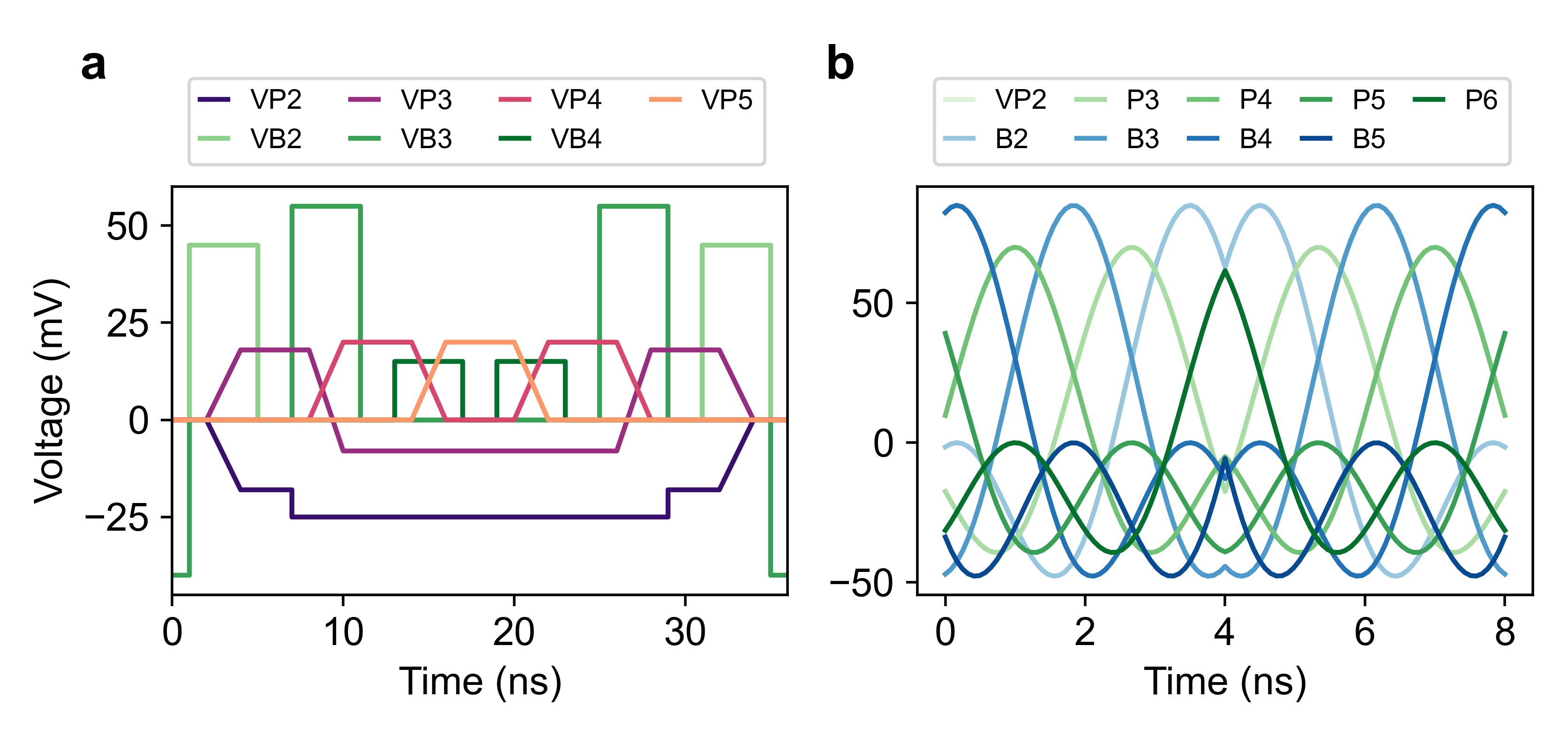
The pulse sequence schematics for BB shuttling in Figure 2d and for CV shuttling in Figure 3a and b are simplified representations of the respective shuttling methods. Supplementary Fig. S1 shows the actual voltage signals applied in the experiments for BB shuttling between dot 2 and 5 (Figure 2e) and CV shuttling during IRB (Figure 4), transporting the spin forth and back once. In bucket-brigade, after the electron has been shuttled through a quantum dot, the dot potential is farther detuned during the next transitions in order to prevent transferring the charge backwards. For the CV measurement, two-tone sinusoidal signals are applied with different amplitudes to gates in different metal layers in order to compensate for the uneven lever arms. Instead of P2, we use the virtual plunger VP2 to avoid changing the electron occupation in quantum dot 1. The spin is transported from approximately underneath gate P5 to P2 and back. To avoid activating the exchange interaction with the reference spin in dot 1, we shuttle up to a conveyor phase offset from under P2. The location of the spin under gate P5 is then determined by the integer 4 ns conveyor time at a frequency of 300 MHz. The DC voltage conditions are given in Table S1. In the conveyor case, these values include pulsed voltage offsets during the entire duration of conveyor operation, as we need different DC voltages while shuttling than during initialization and readout.
| BB | CV | |
|---|---|---|
| VP2 | 1212.82 mV | 1095.91 mV |
| B2 | 771.68 mV | 895.59 mV |
| P3 | 744.92 mV | 626.80 mV |
| B3 | 882.29 mV | 1009.31 mV |
| P4 | 883.65 mV | 789.99 mV |
| B4 | 968.59 mV | 1060.28 mV |
| P5 | 642.24 mV | 581.91 mV |
| B5 | 1135.03 mV | 1170.99 mV |
| P6 | 670.47 mV | 622.13 mV |
| B6 | 763.57 mV | 692.92 mV |
III.2 Considerations on noise sources
In the case of BB shuttling we identify several noise sources that can conceivably lead to shuttling fidelities below the limit set by dephasing in a static dot, in other words to consider phase-flip mechanims that are intrinsically connected to the tunneling events. First, in case the charge transitions are not perfectly adiabatic with respect to the tunnel couplings, the uncertainty in the moment of charge transfer leads to dephasing, as the dots have a different Zeeman splitting. However, given the measured tunnel couplings (Supplementary Fig. S4), the pulse ramp times used, and the simulations in Supplementary Fig. S2, it is unlikely that diabatic transitions will dominate the shuttling performance in the absence of noise. This is further substantiated by the fact that an increasing ramp time lowers the shuttling fidelity, as shown in Figure 2f: in case diabatic transitions were caused by the pulse flanks, the reverse trend would have been observed. However, it is known that high-frequency noise can also cause diabatic transitions [53]. In this case, slower ramps will give noise more time to cause diabatic transitions and the experimentally observed trend agrees with the predicted one.
A next possible mechanism is spin-flip tunneling, which can occur due to the intrinsic spin-orbit interaction (SOI) or an effective SOI from the micromagnet when the tunnel coupling is not large enough compared to the Zeeman splitting. Spin flips caused by tunneling are also visible in shuttling experiments that test how well the spin polarization is preserved. In Si/SiGe devices with a micromagnet, [12] found a spin flip probability 14 times smaller than the phase flip probability, suggesting other phase flip processes are dominant during tunneling.
A plausible BB shuttling limitation, as stated in other works [11, 13], is that charge noise strongly couples to the electron when shuttling through the zero detuning point of the double quantum dots. Given the large Zeeman splitting differences between the two sites of each DQD, the resonance frequency is highly sensitive to detuning fluctuations close to zero detuning (see Supplementary Fig. S4), which leads to enhanced dephasing. The BB shuttling simulations in Supplementary Section C and the experimentally observed dependence of the phase-flip probability on the ramp time corroborates this notion.
Lastly, hyperfine noise can cause spin dephasing. In this case a motional narrowing effect due to shuttling could possibly increase the coherence time, which has been experimentally observed in GaAs [14] and in natSi/SiGe [15]. In this work, no noticeable motional narrowing was detected in bucket-brigade shuttling, though it is worth noting that the present device has only 0.08% magnetic nuclei in the quantum well versus 4.67% for natural silicon devices and 100% in GaAs.
III.3 Simulation of dephasing during bucket brigade shuttling
In this section, we simulate the dephasing during the bucket-brigade shuttling process in the double quantum dots. Following [54], we model the charge and spin dynamics in DQDs using the Hamiltonian
| (6) |
Here, and correspond to the Pauli matrices in the charge and spin sector, respectively. represents the detuning between the two dots, while denotes the tunnel coupling between DQDs. 2 and 2 indicate the differences in the x and z components of the magnetic field between the DQDs, induced by the micromagnet. indicates the external magnetic field (T). When the inhomogeneous magnetic fields are weak, the transverse gradient has a second-order effect on the energy splitting of the spin qubit, while the longitudinal gradient introduces a first-order effect. As a result, the Zeeman splitting can be approximated as
| (7) |
where , and .
Assuming detuning noise which fluctuates on timescales smaller than , and assuming furthermore a small noise amplitude (), we can estimate the dephasing rate for the spin qubit by employing time-independent perturbation theory, as
| (8) | ||||
where , and , where is the standard deviation of the fluctuations .
Assuming a completely adiabatic shuttling process, the phase flip probability due to detuning noise accumulated during shuttling can then be calculated as
| (9) |
where is the detuning ramp time. We note that this expression assumes that the noise fluctuates during the shuttling rounds, as can be expected from motional narrowing effects [15]. This is also consistent with the experimentally observed exponential decay of spin coherence in Ramsey-style shuttling experiments.
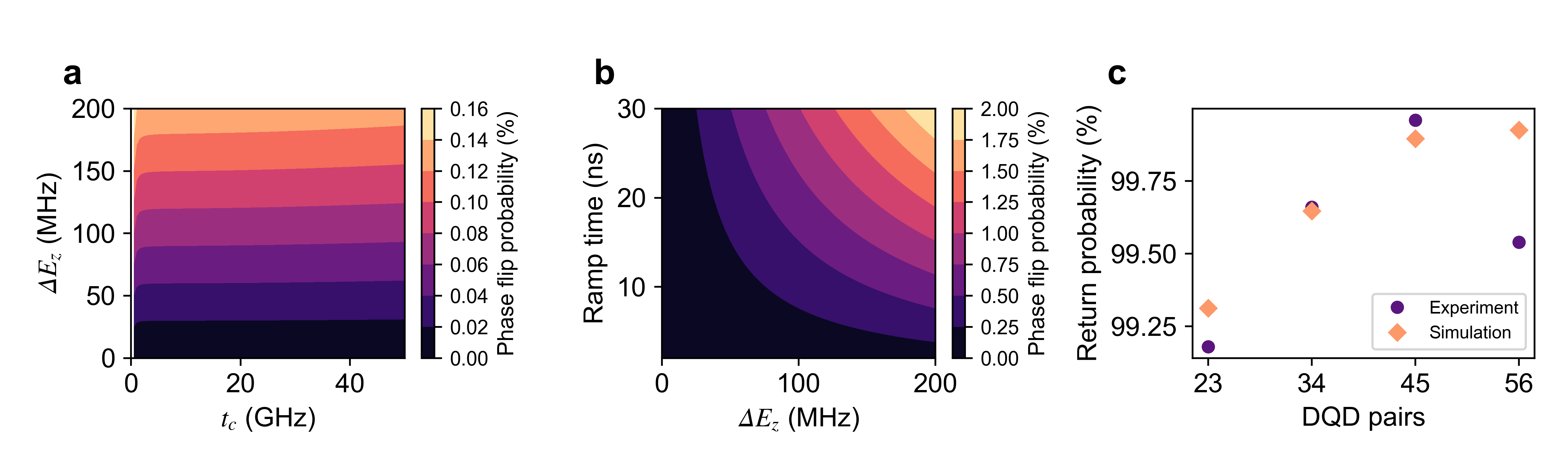
Supplementary Fig. S2a shows the simulated phase flip probability per shuttle hop as a function of and , calculated with , , and .
Supplementary Fig. S2b shows the same simulation but as a function of tunnel coupling and ramp time , calculated with , , and . Similar to the experimental data shown in Figure 2f, the phase flip probability increases as the ramp time increases.
Supplementary Fig. S2c shows a comparison of the return probability obtained from the experiment and the simulation. For the latter, the tunnel couplings and Zeeman splitting differences are extracted from Supplementary Fig. S4. Furthermore, is used, based on the average and , taking into account the difference in measurement time. Except for dot 5-6, the phase flip probability tends to decrease as decreases in both simulation and experiment.
III.4 Lever arms and tunnel couplings in BB
For bucket-brigade shuttling, the tunnel couplings between the dots are crucial for the shuttling performance. Here we estimate the lever arms of the virtual plunger gates and use them to extract the tunnel couplings between the quantum dots. Supplementary Fig. S3a shows the polarization line of the first electron in dot 6 at a mixing chamber temperature of . The barrier to the reservoir is sufficiently closed such that the transition is mostly temperature broadened. This allows us to extract the lever arm of virtual gate VP6 by fitting the transition line to . Here, , , and are fitting parameters and with the Boltzmann constant and the electron temperature, set to . From the slope of the respective (1,0)-(0,1) anticrossings, we extract the relative lever arms of the virtual plunger gates in each double quantum dot. This yields a lever arm value for each virtual plunger gate.
In Supplementary Fig. S4, the tunnel coupling between each quantum dot is obtained by fitting the spin resonance frequency at the interdot transition to , where is the double dot detuning and , , , and are fitting parameters. This corresponds to a simplified picture [49], where we assumed that the tunnel coupling is large compared to the Zeeman splitting, and that spin-dependent tunneling and the Stark shift difference between the dots are negligible.
III.5 Valley splitting
Magnetospectroscopy measurements of the two-electron singlet-triplet energy splittings in this device were performed and reported by [46], albeit in a different cooldown and gate voltage configuration than these shuttling experiments. The estimated values for all quantum dots are indicated in Table S2. is a lower bound for the single-particle valley splitting in strongly confined quantum dots [55] and is also the relevant metric for the size of the Pauli-spin-blockade readout window. For our shuttling experiments, in each quantum dot the singlet-triplet energy splitting is significantly larger than the Zeeman splitting. Dephasing at spin valley hot-spots is therefore suppressed.
| QD 1 | QD 2 | QD 3 | QD 4 | QD 5 | QD 6 |
|---|---|---|---|---|---|
III.6 Dephasing time during conveyor shuttling
The data represented in Figures 3d and 3e show the phase flip probabilities for conventional and two-tone conveyor-mode shuttling per interdot distance . As the transfer speed is varied, the total duration between initialization and readout is not identical for each data point. To investigate the effect of the conveyor shuttling process itself, we can fit the dephasing time of the spin during shuttling. Supplementary Fig. S5 shows this dephasing time when conveyor-mode shuttling during the wait times of Ramsey and Hahn-echo sequences. For conveyor frequencies between 10 and 100 MHz, the average dephasing time during shuttling is for the conventional, and for the two-tone conveyor. In the case of a static conveyor potential shown in Figure 1d, the dephasing time is on average. This increase in dephasing time can likely be explained by motional narrowing. We therefore conclude that, different from the bucket-brigade results, the motion of the conveyor-mode potential does not limit the transfer fidelity, and probably enhances spin coherence.
III.7 Device fabrication
The device used in this work is fabricated on a \ch^28Si/SiGe heterostructure [56]. First, a linearly graded \chSi_1-xGe_x buffer is grown on a Si wafer. On top of that, a relaxed thick \chSi_0.7Ge_0.3 spacer is grown, following by a isotopically purified (800 ppm) tensile-strained \ch^28Si quantum well (QW) [46]. Another \chSi_0.7Ge_0.3 spacer passivated with dichlorosilane at 500 ∘C [57] separates the QW from the gate stack. Ohmic contacts to the two dimensional electron gas in the QW are made using phosphorus-ion implantation. A \chAl2O3 layer precedes three layers of Ti:Pd deposited using electron beam evaporation. The Ti:Pd gate layers have a thickness of 3:17, 3:27, 3:37 , respectively, and are separated by thick \chAl2O3 layers deposited by atomic layer deposition. Finally, another thick \chAl2O3 layer is deposited on top of the gate stack, followed by a 5:200 thick Ti:Co micromagnet, used for addressing and driving of the qubits.
III.8 Bucket-brigade shuttling from quantum dot 2 to 6
In Supplementary Fig. S6 the decay of Ramsey and Hahn-echo fringes during BB shuttling between dot 2 and dot 6 is presented. Bucket brigade shuttling across the entire array is therefore possible. Nonetheless, including dot 6 in the BB chain considerably decreases the shuttling performance. We observe a low lever arm of gate B5 and a small charging energy in dot 5. We speculate that the small orbital energy could induce diabatic charge excitations. Given the artificial spin-orbit interaction from the micromagnet, this would affect not only the spin dephasing rate (phase flips) but also the spin relaxation rate (spin flips) during shuttling. In Supplementary Fig. S7 the spin polarization as a function of the number of shuttle hops is shown. The relaxation rate is very small when the spin is shuttled between quantum dot 2 and 5. When shuttling between quantum dot 2 and 6, the relaxation rate increases dramatically.
III.9 Two-tone conveyor shuttling fidelity with equal DC voltages
In Figure 3c we demonstrate that conveyor-mode shuttling with equal DC offsets is possible, though requiring higher pulse amplitudes. Here we show interleaved randomized benchmarking of shuttling using a two-tone conveyor at 80 MHz while emulating a lack of individual gate control. To do so, the conveyor amplitude is set to 90 mV for each gate, regardless of the gate layer. This is with the exception of VP2 (70 mV), as needed to keep the reference electron confined in dot 1. We apply pulse offsets such that the barrier gates B2, B3, B4 and B5 in the conveyor are set to a DC voltage of 900 mV, and the plunger gates P3, P4, P5 and P6 are set to a DC voltage of 710 mV while shuttling. Gates on the edges of the device were exempted as they are not only crucial for the initialization and readout, but also for the transition of the single electron into the conveyor. Moreover, it is imperative to avoid losing the shuttled electron to the reservoirs. In Supplementary Fig. S8 the fidelity for shuttling over a distance of 432 nm without individual gate control is determined to be 99.18 0.19 %. Extrapolating to the from the case with individual DC control, this amounts to a fidelity of 65.08 2.90 %.
III.10 Required conveyor amplitude corrected for AWG filter
Whereas Figure 3c takes into account the attenuation in the transmission lines, it does not consider the output filter of the waveform generator. In Supplementary Fig. S9 we correct for the phase and amplitude distortion of the applied sine signals using the measured AWG filter function. Note that in the two-tone case, the filter response is different for both sine waves, leading to an alteration of the shape of the traveling wave potential with increasing conveyor frequency. Therefore, here we indicate the peak-to-peak voltage of the applied signals. It is not clear to us why the required peak-to-peak voltage for successful charge transfer (slightly) decreases with conveyor frequency for the two-tone implementation with equal DC voltages. If anything, we were a priori expecting that higher amplitudes might be needed for higher conveyor frequencies, as seen for the other two cases shown. As stated in the main text, smaller amplitudes are required for the two-tone conveyor than for the conventional conveyor. This is what we were expecting given that the potential barriers surrounding a moving dot are wider for the two-tone conveyor (see also the diagrams in Fig. 3a,b), and an electron is therefore less likely to escape from the potential minimum in which it is meant to travel.