Zak-OTFS and Turbo Signal Processing for Joint Sensing and Communication
Abstract
The Zak-OTFS input/output (I/O) relation is predictable and non-fading when the delay and Doppler periods are greater than the effective channel delay and Doppler spreads, a condition which we refer to as the crystallization condition. The filter taps can simply be read off from the response to a single Zak-OTFS pilot pulsone, and the I/O relation can be reconstructed for a sampled system that operates under finite duration and bandwidth constraints. In previous work we had measured BER performance of a baseline system where we used separate Zak-OTFS subframes for sensing and data transmission. In this Letter we demonstrate how to use turbo signal processing to match BER performance of this baseline system when we integrate sensing and communication within the same Zak-OTFS subframe. The turbo decoder alternates between channel sensing using a noise-like waveform (spread pulsone) and recovery of data transmitted using point pulsones.
Index Terms:
Zak-OTFS, Integrated Sensing and Communication, Turbo processing.I Introduction
6G propagation environments are changing the balance between time-frequency methods focused on OFDM signal processing and delay-Doppler methods (OTFS) [1, 3, 4, 5, 6]. OFDM is configured to prevent inter-carrier-interference (ICI) whereas OTFS is configured to embrace ICI [7, 8, 9, 10, 11, 12]. In OFDM, once the I/O relation is known, equalization is relatively simple at least when there is no ICI. However, acquisition of the I/O relation is non-trivial and dependent on the accuracy of the assumed propagation model [13]. In contrast, equalization is more involved in OTFS due to inter-symbol-interference (ISI), however acquisition of the I/O relation is simple and model free [14, 15, 16, 17]. Acquisition becomes more critical when Doppler spreads measured in KHz make it more and more difficult to estimate channels. The most challenging situation is the combination of unresolvable paths and high channel spreads. In this Letter we present simulation results for a Veh-A channel [18] where the first three paths are not separable and cannot be estimated accurately.
In previous work [14, 15] we have described how to design a parametric family of pulsone waveforms that can be matched to the delay and Doppler spreads of different propagation environments. A pulsone is a signal in the time domain which realizes a quasi-periodic localized function on the DD domain. The prototypical structure of a pulsone is a train of pulses modulated by a tone. We have analyzed performance in the situation when the pulsone parameters matches the environment channel parameters, in the sense that, the delay period of the pulsone is greater than the delay spread of the channel, and the Doppler period of the pulsone is greater than the Doppler spread of the channel. We refer to this condition as the crystallization condition. We start from this baseline system where we dedicate separate Zak-OTFS subframes to channel estimation and data transmission, abbreviated as (sensing/channel estimation in the absence of communication signal) and (communication in the absence of sensing signal).
The characteristic structure of a pulsone is a train of pulses modulated by a tone, a signal with unattractive peak-to-average power ratio (PAPR). In more recent work [19] we have introduced the notion of filtering in the discrete delay-Doppler domain. We have described how to construct spread waveforms with desirable characteristics by applying a chirp filter in the discrete DD domain to a point pulsone. One desirable characteristic is low PAPR, about 6dB for the exemplar spread pulsone, compared with about 15dB for the point pulsone. A second desirable characteristic is the ability to read off the I/O relation of the sampled communication system provided a second crystallization condition is satisfied. This work demonstrates how to integrate sensing and communication within a single Zak-OTFS subframe by combining a spread pulsone for channel sensing with point pulsones for data transmission. The filter in the discrete DD domain enables coexistence by minimizing interference between sensing and data transmission. We have demonstrated that sharing DD domain resources in this way increases effective throughput compared with traditional approaches that use guard bands to divide DD domain resources between sensing and communication.
In this Letter we demonstrate that turbo signal processing is able to close the performance gap between separate sensing and communication ( and ) and joint sensing and communication in the same Zak-OTFS subframe (which we abbreviate as and ). The turbo principle of iterating between functional blocks in communication receivers has proven to be a powerful method of improving performance. For example, turbo iterations between channel equalizer and channel decoder have been shown to yield tremendous improvements in bit error performance [20], [21]. Likewise, iterations between channel estimation and turbo equalizer have been shown to improve the channel estimate over the iterations by using soft information fed back from the decoder from the previous iteration to generate extended training sequences between the actual transmitted training sequences [22].
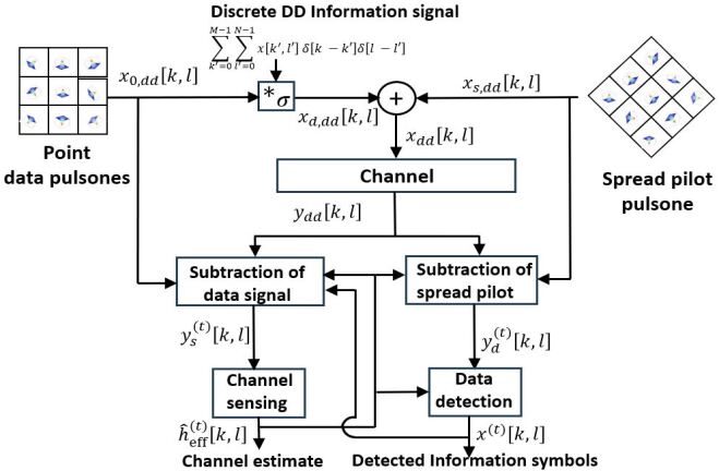
In joint sensing and communication, we estimate the effective channel, then estimate the received spread pilot, then recover the data after subtracting our estimate for the received pilot from the received signal (see Fig. 1). The residual pilot (after cancellation) interferes with data transmission. In the turbo iteration, we take the estimated data, then estimate the received data signal, then improve our estimate for the effective channel by subtracting our estimate for the received data signal from the received signal. We show that five turbo iterations suffice to match the performance of separate sensing and communication across a wide range of Doppler shifts.
II System model
In previous work [19] we have introduced a framework for joint sensing and communication where the pilot/sensing signal and the data signal are embedded in a single Zak-OTFS subframe. We recall [19] that Zak-OTFS carrier waveforms are quasi-periodic functions in the discrete DD domain with period along the discrete delay axis and period along the discrete Doppler axis. The superposition of pilot and data signals in the discrete DD domain is given by
| (1) |
where denotes the energy of the pilot and the energy of the data signal. The ratio is therefore the pilot to data power ratio (PDR). The data signal , is given by
| (2) |
where each of the information symbols , , have average energy . The exponential phase term in (2) renders quasi-periodic. For all
| (3) |
The data signal in (1) can also be expressed in terms of filtering (in the DD domain) a quasi-periodic DD domain pulse at the origin.
| (4) | |||||
where
| (5) |
is the data pulsone corresponding to a DD pulse at the origin. DD domain filtering is implemented through twisted convolution and the filter taps in (4) depend on the information symbols. The pilot signal in (1) is given by
| (6) |
where the spreading filter acts on the point pilot by twisted convolution. We follow [19] by considering chirp filters, where for ,
| (7) |
and we refer to as the slope parameter. The point pilot appearing in (6) is a discrete DD domain quasi-periodic impulse located at and is given by
| (8) |
We then lift the discrete DD domain signal given by (1) to obtain a continuous DD domain signal
| (9) |
that is quasi-periodic with delay period and Doppler peirod . We then apply a pulse shaping filter to limit the transmitted TD signal to the duration and bandwidth of the Zak-OTFS subframe. This TD signal is obtained by applying the inverse Zak transform to the filtered DD domain signal .
Matched filtering at the receiver using followed by sampling on the information grid results in the discrete DD domain signal given by
| (10) | |||||
where represents noise in the discrete DD domain. Note that it is associativity of twisted convolution that allows us to represent a cascade of filters/channels as a single effective channel filter . In our previous work [19] we have described how the receiver senses the channel (estimates ) from the cross-ambiguity between and the transmitted spread pilot . We recall (Theorem from [19]) that
where is the self-ambiguity function of the spread pilot signal, and are the cross-ambiguity functions of the transmitted data signal and noise signal respectively with the spread pilot signal.
The self-ambiguity function of the point pilot is supported on the period lattice comprising integer linear combinations of and .
We have shown [19] that the self-ambiguity function of the spread pilot is supported on a lattice obtained by rotating . Let denote the support region of the effective channel in the discrete DD domain. The crystallization conditions with respect to the lattice are satisfied if the translates of by lattice points in are disjoint. In this case, we can obtain the effective channel tap by evaluating the first term of (II) at points in a fundamental domain of . The second term in (II) represents interference to sensing from data. We recall (Theorem from [19]) that the magnitudes are essentially independent of so that interference from data to sensing is noise-like (see also Fig. from [19]). The third term in (II) represents interference to sensing from noise. We recall (Appendix J from [19]) that is zero-mean Gaussian distributed with variance essentially independent of . Our estimate of is then
| (12) |
We suppose that the crystallization conditions are also satisfied with respect to the lattice . We use the estimate (12) to cancel the contribution made by the pilot to the received DD signal. After cancellation, the signal
| (13) |
is used to recover the data using the matrix-vector formulation of the Zak-OTFS I/O relation (see [15] for details).
By spreading the pilot signal, we integrate sensing and communication within the same Zak-OTFS subframe. Sharing DD domain resources in this way increases effective throughput compared with traditional approaches that use guard bands to divide DD domain resources between sensing and communication (see Fig. from [19]). Spreading also reduces the PAPR of the pilot signal to about dB compared with dB for the original point pilot (see Fig. and Fig. from [19]).
We recall that integrated sensing and communication with spread pilots results in an uncoded -QAM BER of about , compared with for sensing and communication in separate Zak-OTFS subframes (see Fig. from [19]). The difference is three orders of magnitude. Section III describes a turbo signal processing method that is able to close this gap.
III Iterative Sensing and Communication
In this Section we describe the iterative signal processing algorithm illustrated in Fig. 1. The first iteration is described in Section II and the iteration consists of four steps.
STEP : Inputs are the detected information symbols , , and estimated channel filter taps from iteration . We form (see (LABEL:eqn196402) at top of page) and subtract this estimate for the received data signal from the received signal to obtain
| (15) |
The output is a data cancelled signal that approximates the received spread pilot.
STEP : We use (12) to form the estimate for the effective channel filter taps
| (16) |
STEP : We use , to form the estimate of the received pilot signal using
| (17) |
We subtract this estimate from the received signal to obtain
| (18) |
This output is a pilot cancelled signal that approximates the received data signal.
STEP : We detect data/information symbols from using the method described in Section II. We then move to STEP of iteration , and the algorithm halts after a fixed number of iterations.
Section IV presents numerical simulations illustrating that multiple iterations improve the fidelity of the data cancelled and pilot cancelled signals.
| Path number () | 1 | 2 | 3 | 4 | 5 | 6 |
|---|---|---|---|---|---|---|
| (s) | 0 | 0.31 | 0.71 | 1.09 | 1.73 | 2.51 |
| Relative power () dB | 0 | -1 | -9 | -10 | -15 | -20 |
IV Numerical simulations
This Section reports simulation results for the Veh-A channel model [18] which consists of six channel paths. The channel gains are modeled as independent zero-mean complex circularly symmetric Gaussian random variables, normalized so that . Table I lists the power-delay profile for the six channel paths. The Doppler shift of the -th path is modeled as , where is the maximum Doppler shift of any path, and the variables , , are independent and distributed uniformly in .
We consider Zak-OTFS modulation with Doppler period KHz, delay period ms, and . The channel bandwidth MHz and the subframe duration ms. Note that the first three channel paths introduce delay shifts in the interval ms and each is less than the delay resolution. We consider matched filtering using root raised cosine (RRC) pulse shaping filters with roll-off factors . This increases the subframe duration to ms and the bandwidth to MHz. We consider a spread pilot pulsone constructed using a chirp filter in the discrete delay-Doppler domain ((7) with ) as described in [19]. We implement the turbo signal processing pipeline illustrated in Fig. 1 using MMSE equalization to recover information symbols using the effective channel matrix.
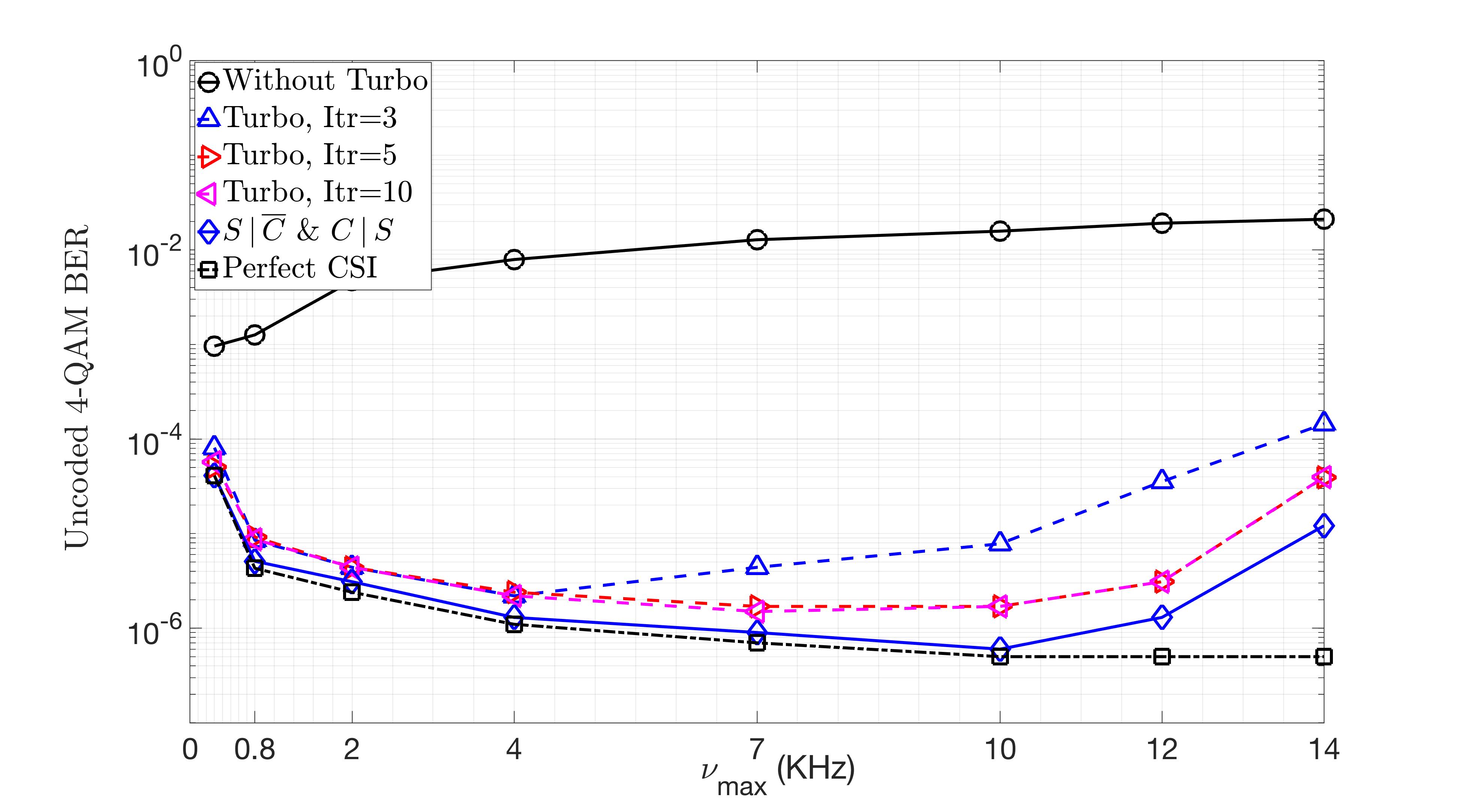
For a fixed data SNR of dB we set the PDR to dB so that the pilot power is sufficient to start the turbo process. Fig. 2 illustrates that in the crystalline regime, five turbo iterations (dashed curve with red triangles) are sufficient to match the BER performance of separate sensing and communications (dashed curve with black squares). When KHz the estimate of the effective channel becomes less accurate because of Doppler domain aliasing, and BER performance degrades because interference from the residual pilot becomes more significant than noise. We focus on the role of channel estimation by designing a reference system (solid blue curve with diamonds) where sensing takes place in a separate subframe () but data transmission is still subject to interference from the residual pilot (). Fig. 2 illustrates that BER performance with five turbo iterations differs from that of the reference system by a small SNR offset.
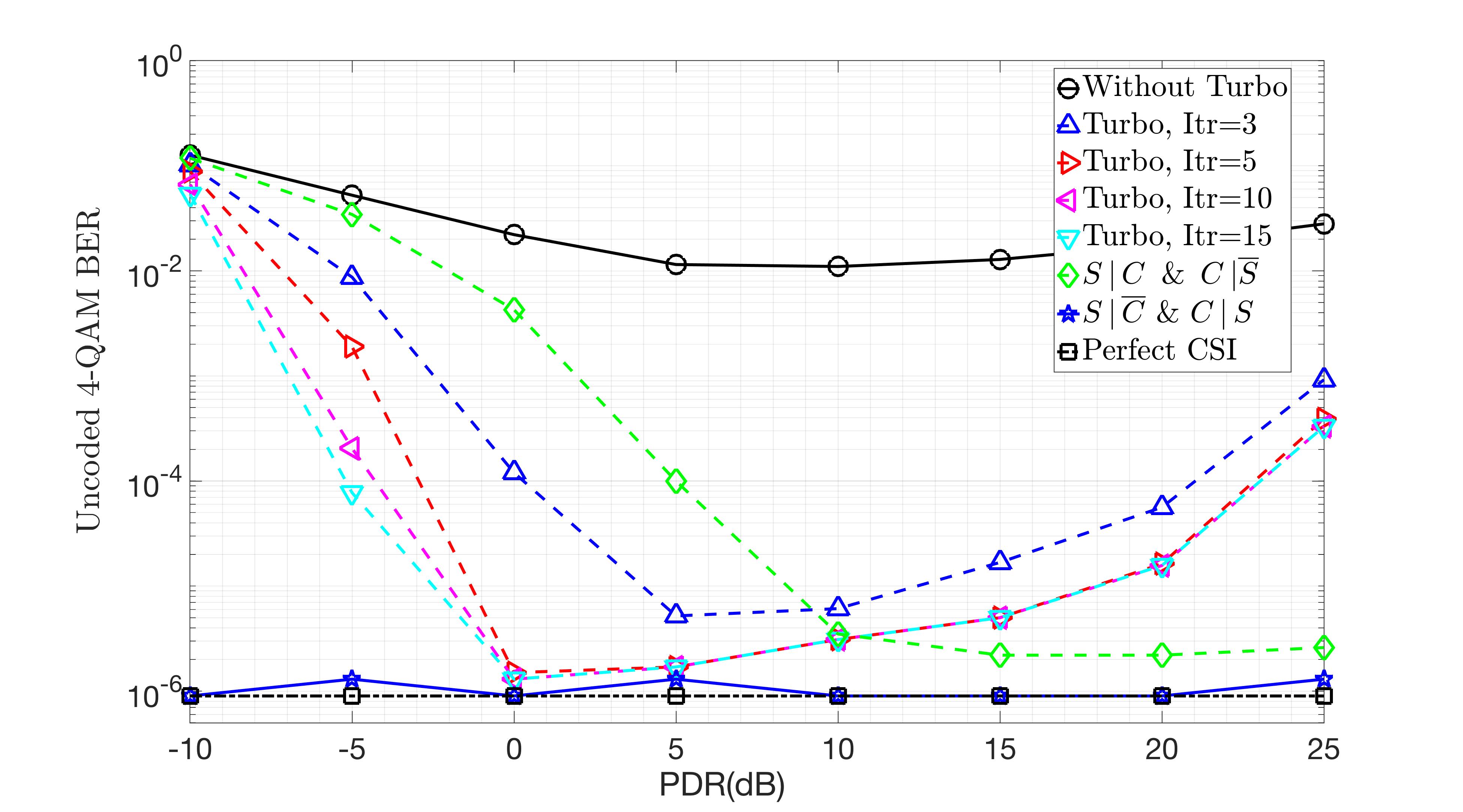
Next we consider how BER performance depends on PDR, and we set KHz so that we are operating deep in the interior of the crystalline regime. Fig. 3 illustrates that when PDR dB the pilot power is not sufficient to start the turbo process, that the initial estimate of the effective channel is not sufficiently accurate. When PDR dB interference from the residual pilot (after cancellation) is more significant than noise, and BER degrades as PDR increases. For intermediate values of the PDR, BER performance improves with increasing PDR as estimates of the effective channel become more accurate. This explains the characteristic “U” shape of the intermediate curves in Fig. 3. Again, we focus on the role of channel estimation by considering the reference system described above ( and ), where the residual pilot has very little energy and interference offered to the transmitted data is inconsequential (channel estimation is very accurate since it is based on a separate sensing-only subframe). We also consider a second reference system (green curve with diamonds), where sensing is subject to interference from data (), but data recovery is not subject to interference from a residual pilot (). Data is transmitted in a separate subframe and there are no turbo iterations for this second reference system. Fig. 3 confirms that interference from the residual pilot is responsible for the degradation in BER performance with increasing PDR.
V Conclusions
We started by observing that the uncoded 4-QAM BER performance of sensing and communications in separate Zak-OTFS subframes is three orders of magnitude better than that of integrated sensing and communication with spread pilots. In joint sensing and communication, we estimate the effective channel, then estimate the received spread pilot, then recover the data after subtracting our estimate for the received pilot from the received signal. The residual pilot (after cancellation) interferes with data transmission, and we showed that this is the reason for the three orders of magnitude gap in performance. We described a turbo signal processing algorithm that alternates between channel sensing using a spread pilot and data recovery. We showed that five turbo iterations suffice to match the performance of separate sensing and communication across a broad range of Doppler shifts.
References
- [1] H. Tataria, M. Shafi, A. F. Molisch, M. Dohler, H. Sjöland, and F. Tufvesson, “6G wireless systems: Vision, requirements, challenges, insights, and opportunities,” Proceedings of the IEEE, vol. 109, no. 7, pp. 1166-1199, Jul. 2021.
- [2]
- [3] C. -X. Wang, X. You, X. Gao, X. Zhu, Z. Li, C. Zhang, H. Wang, Y. Huang, Y. Chen, H. Haas, J. S. Thompson, E. G. Larsson, M. Di Renzo, W. Tong, P. Zhu, X. Shen, H. V. Poor, and L. Hanzo, “On the road to 6G: Visions, requirements, key technologies, and testbeds,” IEEE Commun. Surveys & Tuts., vol. 25, no. 2, pp. 905-974, 2023.
- [4] R. Hadani et al., “Orthogonal time frequency space modulation,” Proc. IEEE WCNC’2017, pp. 1-6, Mar. 2017.
- [5] Z. Wei, W. Yuan, S. Li, J. Yuan, G. Bharatula, R. Hadani and L. Hanzo, “Orthogonal time-frequency space modulation: a promising next-generation waveform,” IEEE Wireless Commun. Mag., vol. 28, no. 4, pp. 136-144, Aug. 2021.
- [6] W. Yuan et al., “Best readings in orthogonal time frequency space (OTFS) and delay Doppler signal processing,” Jun. 2022. https://www.comsoc.org/publications/best-readings/orthogonal-time-frequency-space-otfs-and-delay-doppler-signal-processing.
- [7] A. Monk, R. Hadani, M. Tsatsanis, and S. Rakib, “OTFS - orthogonal time frequency space: a novel modulation meeting 5G high mobility and massive MIMO challenges,” arXiv:1608.02993 [cs.IT] 9 Aug. 2016.
- [8] P. Raviteja, K. T. Phan, Y. Hong, and E. Viterbo, “Embedded pilot aided channel estimation for OTFS in delay-Doppler channels,” IEEE Trans. Veh. Tech., vol. 68, no. 5, pp. 4906-4917, May 2019.
- [9] P. Raviteja, Y. Hong, E. Viterbo, and E. Biglieri, “Practical pulse-shaping waveforms for reduced-cyclic-prefix OTFS,” IEEE Trans. Veh. Tech., vol. 68, no. 1, pp. 957-961, Jan. 2019.
- [10] C. Shen, J. Yuan, and H. Lin, “Error performance of rectangular pulse-shaped OTFS with practical receivers,” IEEE Wireless Commun. Lett., vol. 11, no. 12, pp. 2690-2694, Dec. 2022.
- [11] S. K. Mohammed, “Derivation of OTFS modulation from first principles,” IEEE Trans. Veh. Tech., vol. 70, no. 8, pp. 7619-7636, Aug. 2021.
- [12] S. K. Mohammed, “Time-domain to delay-Doppler domain conversion of OTFS signals in very high mobility scenarios,” IEEE Trans. Veh. Tech., vol. 70, no. 6, pp. 6178-6183, Jun. 2021.
- [13] E. Panayirci, H. Senol, and H. V. Poor, “Joint channel estimation, equalization, and data detection for OFDM systems in the presence of very high mobility,” IEEE Trans. Signal Process., vol. 58, no. 8, pp. 4225-4238, Aug. 2010.
- [14] S. K. Mohammed, R. Hadani, A. Chockalingam, and R. Calderbank, “OTFS – A mathematical foundation for communication and radar sensing in the delay-Doppler domain,” IEEE BITS the Information Theory Magazine, vol. 2, no. 2, pp. 36-55, 1 Nov. 2022.
- [15] S. K. Mohammed, R. Hadani, A. Chockalingam, and R. Calderbank, “OTFS – Predictability in the delay-Doppler domain and its value to communications and radar sensing,” IEEE BITS the Information Theory Magazine, IEEE early access, doi: 10.1109/MBITS.2023.3319595, Sep. 2023.
- [16] S. Li, W. Yuan, Z. Wei, J. Yuan, B. Bai, and G. Caire, “On the pulse shaping for delay-Doppler communications,” IEEE GLOBECOM’2023, pp. 4909-4914, Dec. 2023.
- [17] S. Gopalam, I. B. Collings, S. V. Hanly, H. Inaltekin, S. R. B. Pillai, and P. Whiting, “Zak-OTFS implementation via time and frequency windowing,” IEEE Trans. Commun., IEEE early access, doi: 10.1109/TCOMM.2024.3366403.
- [18] ITU-R M.1225, “Guidelines for evaluation of radio transmission technologies for IMT-2000,” International Telecommunication Union Radio communication, 1997.
- [19] M. Ubadah, S. K. Mohammed, R. Hadani, S. Kons, A. Chockalingam, and R. Calderbank, “Zak-OTFS for integration of sensing and communication,” available online: arXiv:2404.04182v1 [eess.SP] 5 Apr 2024.
- [20] C. Douillard et al., “Iterative correction of intersymbol interference: turbo-equalization,” Eur. Trans. Telecommun., vol. 6, pp. 507-511, Sep.-Oct. 1995.
- [21] M. Tüchler, R. Koetter, and A. C. Singer, “Turbo equalization: principles and new results,” IEEE Trans. Commun., vol. 50, no. 5, pp. 754-767, May 2002.
- [22] R. Otnes and M. Tuchler, “Iterative channel estimation for turbo equalization of time varying frequency selective channels,” IEEE Trans. Wireless Commun., vol. 3, pp. 1918-1923, Nov. 2004.