Embracing Nonlinearity and Geometry: A dimensional analysis guided design of shock absorbing materials
Abstract
Protective applications require energy-absorbing materials that are soft and compressible enough to absorb kinetic energy from impacts, yet stiff enough to bear crushing loads. Achieving this balance requires careful consideration of both mechanical properties and geometric design. Conventional shock-absorbing pads are made of very thick foams that exhibit a plateau of constant stress in their stress-strain response. Contrary to this belief, we report that foams with a nonlinear stress-strain response can be useful to achieve simultaneously thin and lightweight protective pads. We introduce a new framework for the thickness or volume-constrained design of compact and lightweight protective foams while ensuring the desired structural integrity and mechanical performance. Our streamlined dimensional analysis approach provides geometric constraints on the dimensionless thickness and cross-sectional area of a protective foam with a given stress-strain response to limit the acceleration and compressive strain within desired critical limits. We also identify optimal mechanical properties that will result in the most compact and lightest protective foam layer for absorbing a given kinetic energy of impact. Guided by this design framework, we achieve optimal protective properties in hierarchically architected vertically aligned carbon nanotube (VACNT) foams, enabling next generation protective applications in extreme environments.
Keywords: Architected foams, Helmet Liner, Shock absorber design, Traumatic brain injury, VACNT arrays
Introduction
Energy-absorbing materials permeate our lives, from soft polymeric foams used in helmet liners [1, 2], packaging [3], and seat cushions, to crushable metallic foams employed in ballistic impact attenuators [4, 5], automotive buffers, and planetary landers [6]. Those protective foams must absorb the kinetic energy from impacts and undesirable vibrations while limiting the forces and accelerations imparted on the protected objects [7, 3]. Compared to stochastic foams, architected foams demonstrate superior modulus, strength, and energy absorption at comparable or lower densities [8]. This indicates better specific properties or density-normalized properties, achieved through architectural design of the lattice unit cells [9, 10, 11, 12]. The pursuit of achieving specific mechanical properties near the theoretical limits has resulted in several advancements [13, 9], including ultra-stiff micro-lattices [14, 15], nanolattices with high mechanical strength [9, 16], high energy-absorption of supersonic projectiles [17, 18], and fracture resilience in hierarchical [19, 20] and woven architectures [21]. While the field of architected materials is thriving with advancements on improving specific mechanical properties, the role of the sample geometry of the energy absorbing material and its interplay with the mechanical properties towards meeting critical performance criteria has been overlooked. For example, it is well understood that helmet liners designed to prevent traumatic brain injury during extreme sports or combat require not only high specific energy absorption capacity but also the ability to limit peak accelerations below a critical value [22, 2].
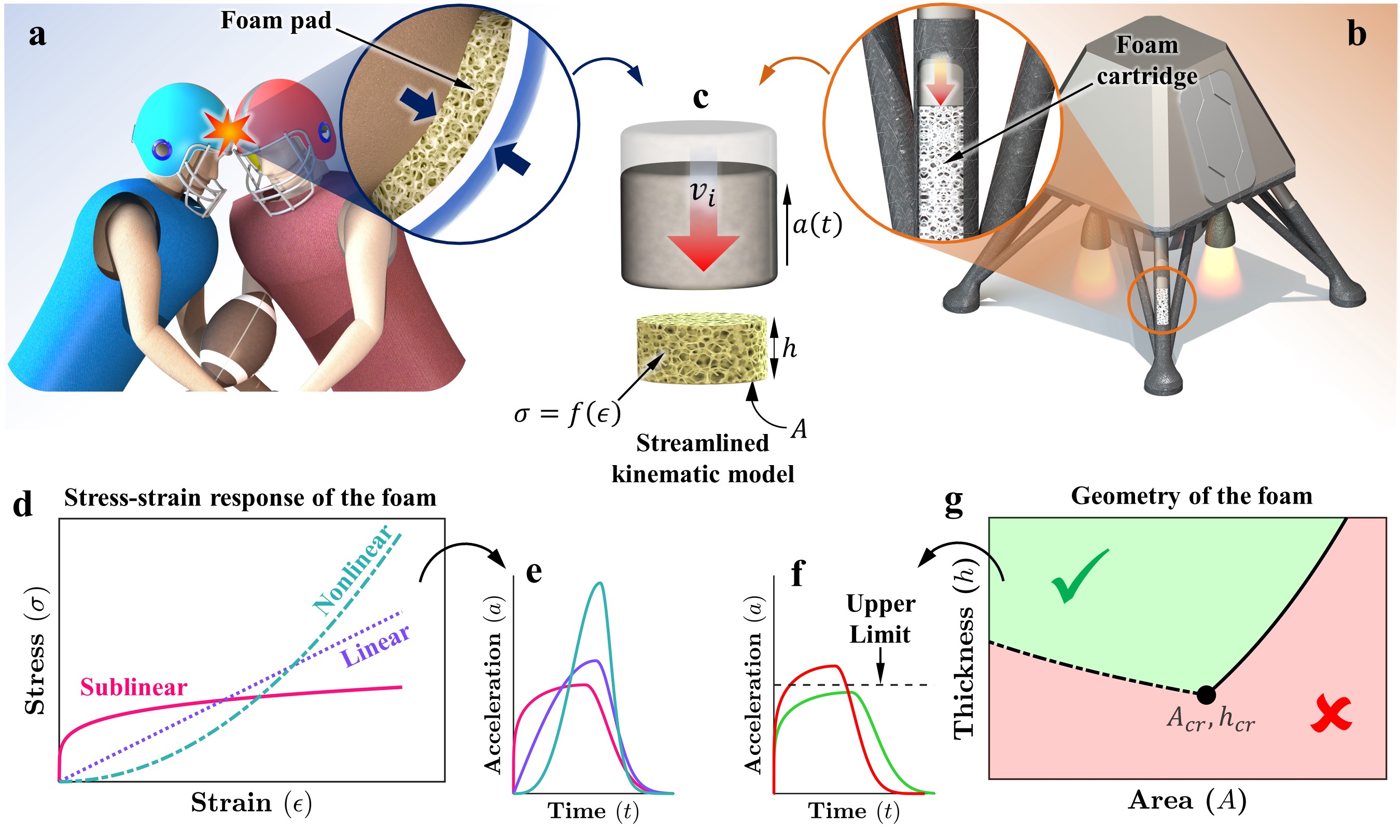
This interplay between the intrinsic properties of the foam and the protective layer’s geometry is governed by three important mechanical properties of foams: relative density (), the scaling of relative modulus with relative density , and the characteristic shape of the stress-strain response. The relative density, which is the ratio of the foam’s bulk density () to the density of its solid counterpart (), controls the compressibility of the foam. A porous foam with a low relative density can be compressed to larger strains before reaching the densification regime beyond which the stress rapidly increases, diminishing the foam’s effectiveness. The relative modulus of all cellular materials has been observed to scale with relative density . The scaling exponent is determined by the morphology and the deformation mechanism and typically falls within the range [23, 24, 15]. A linear scaling exponent is generally desirable because it allows achieving higher modulus and greater specific energy absorption without significantly increasing the foam’s density [10, 15]. The protective performance of the foams also depends on the characteristic shape of the stress-strain response (Figure 1(d)). Foams with a plateau-like sublinear stress-strain response are typically considered desirable, allowing absorption of a given amount of energy at a lower stress levels. A desirable protective foam, hence, should exhibit high porosity, a near-linear scaling of modulus with density, and a plateau-like sublinear stress-strain curve.
Traditionally, foams exhibiting properties similar to those mentioned above are considered suitable for nearly all protective applications. Contrary to this belief, we report that foams with steeper scaling () and nonlinear stress-strain behavior can be beneficial in achieving compact and lightweight energy-absorbing pads. Using a streamlined kinematic model and dimensional analysis, we derive guidelines for geometric design and discover optimal mechanical properties resulting in the thinnest and lightest energy absorbing foam pads. Guided by these derived criteria, we design, synthesize, characterize, and demonstrate optimal performance in hierarchically architected vertically aligned carbon nanotube (VACNT) foams. Freestanding VACNT foams, synthesized via the FCCVD (Floating Catalyst Chemical Vapor Deposition) process, are renowned for being simultaneously stiff and lightweight, as well as, for exhibiting remarkably high specific energy absorption [25, 26], which rivals that of crashworthy metallic foams and architected foams [23]. These properties are attributed to their multi-scale hierarchical structure with the nanoscale interactive fibrous morphology. Unlike metallic foams and architected foams, which often fail in a brittle manner and lack strain recovery, VACNT foams can recover near completely from compressive strains as large as 90% [25]. Furthermore, they exhibit high thermal conductivity [27] and maintain consistent mechanical properties across a wide range of strain rates and temperatures [28, 29], making them suitable for protective applications in extreme environments.
Using photolithography, we introduced an additional level of structural hierarchy in VACNT foams by creating mesoscale patterns [30, 23, 31]. Incorporating various geometries of mesoscale patterns opens a broad range of tunability in relative density, constitutive response, and density-dependent scaling of mechanical properties. Our hierarchical architecture design of VACNT foams yields optimal pad geometries subjected to imposed constraints on peak acceleration and maximum compression strain. For example, a bio-inspired higher-order fractal architecture and a sparsely packed cylindrical architecture exhibiting nonlinear stress-strain response enable protective pads with minimum mass. On the other hand, a concentric cylinder architecture with sublinear plateau-like stress-strain response results in more thin and compact protective pads. Our design framework and its effective demonstration on the hierarchically architected VACNT foams provide a comprehensive approach to designing architected materials for superior performance. Our work provides guidance on achieving enhanced protective performance with imposed constraints on geometric and physical properties within the vast material design space offered by machine learning [32, 33] and statistical design of experiments [31].
The foundation of the design framework
Energy-absorbing pads can take various geometries depending on the application, such as a flat comfort pad in helmet liners (Figure 1(a)) or a long cylindrical cartridge in planetary landers (Figure 1(b)). In all cases, during an impact, the foam is compressed in the direction of impact, absorbing kinetic energy while minimizing the imparted load and recoil. The impact scenarios depicted in Figure 1(a,b) can be described by the simplified equation of motion corresponding to an impacting mass compressing the protective foam with an initial impact velocity resulting in swift acceleration (retardation) to rest (Figure 1(c)). Assuming that the foam compresses uniformly within an area and thickness (or height) , the force acting on the mass during acceleration will be equivalent to the magnitude of force developed in the foam, as follows:
| (1) |
with the initial conditions:
| (2) |
where is the compression in the foam, represents time, is the acceleration due to gravity, and is the stress response of the foam, with the subscript indicating that the foam is being loaded (compressed) by the impact. We describe the constitutive stress-strain response of the foam by an empirical power law equation [34] as follows
| (3) |
where is an elastic modulus, and the exponent governs the shape of the constitutive stress-strain response. By varying , various stress-strain curves, such as those exhibiting sublinear , linear , and nonlinear behaviors, can be modeled for parametric analysis. Integrating equation 3 up to a compression strain , we obtain the expression for energy absorption per unit volume as follows,
| (4) |
In the above expression, is inversely related to . This suggests that for a nonlinear stress-strain response , the energy absorbed will be significantly smaller than that of a sublinear stress-strain response , which is not true for real materials [35]. Generally, materials with nonlinear stress-strain response absorb either a similar amount or more energy up to the onset of densification strain [35, 23]. To account for the effect of , we scale the power law expression in equation 3 by multiplying with (see Figure S1 in SI) as follows:
| (5) |
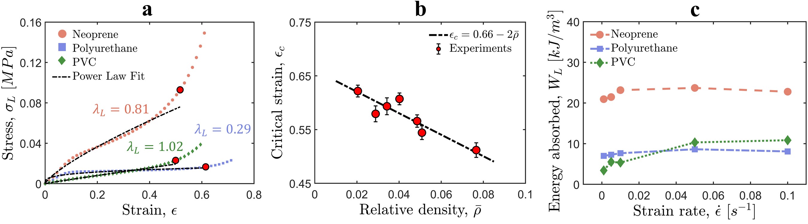
where the exponent determines the relative difference in modulus among a set of foams with various values. As shown in Figure 2(a), the power law equation captures the experimentally measured stress-strain response up to the onset of densification (indicated by red dots)—all measured at the same strain rate—fairly well for different open-cell elastomeric foams. These power-law fits yield the effective modulus of the foam and a dimensionless exponent that describes the shape of the stress-strain curve. The strain at the onset of densification, also called critical strain , is where the energy absorption efficiency of the foam reaches the maximum, beyond which it declines rapidly [36]. The critical strain is slightly smaller than the actual densification strain where the slope of the stress-strain curve becomes almost vertical [7]. While a foam does keep absorbing more energy for , the transmitted force rises sharply making foam ineffective. Hence, a foam’s performance is characterized based on the amount of energy it can absorb before the onset of densification . We measured the critical strain of different polymeric foams using the energy absorption efficiency method [36] and observe a linear relationship between the critical strain and the relative density of the foam (Figure 2(b)). Noteworthy is that this linear fit extrapolates to for , which matches the relative density of foams reported in literature which do not have a plateau region and exhibit densification immediately after the linear elastic regime [7]. In addition to the critical strain, the modulus of the foam also depends on the relative density as mentioned in the introduction:
| (6) |
Here, and represent the modulus and density, respectively, of the solid material utilized in foam fabrication, denotes a scaling exponent that is a function of the foam’s morphology and deformation mechanism, and is a constant of proportionality [37]. Utilizing equation 6, the stress-strain relationship for the foam can be expressed as,
| (7) |
where represents the compressive strain . The stress response in equation 7 is independent of the strain rate while the most polymeric and elastomeric foams are strain-rate sensitive. This rate dependency is generally incorporated into constitutive models by multiplying a rate-dependent viscous damping term to the elastic term [38]. However, we observe that the specific energy absorbed—the area under the stress-strain curve up to the critical strain—as a function of the strain rate we measured experimentally on various open-cell elastomeric foams show only a mild strain-rate effect with it initially increasing and then becoming almost constant (Figure 2(c)). While some foams exhibit rate dependency up to much higher strain rates, their response eventually stabilizes [39]. Moreover, our VACNT foams exhibit rate-independent behavior from quasistatic to very large strain rates [28, 29]. Therefore, adding a rate-dependent term in equation 7 is not worth considering. To make our modeling scale-free, we establish the following dimensionless variables:
| (8) |
Here, represents the maximum acceleration limit that the protected object should not exceed. This limit depends on the object’s structural resilience or physiological tolerance, for example, the allowable peak acceleration in the case of traumatic brain injury prevention [40]. By substituting the dimensionless variables (Equation 8) and stress-strain relation (Equation 7) into equation 1 and equation 2, we arrive at the following dimensionless governing equation and dimensionless initial conditions:
| (9) |
| (10) |
Usually , so the term can be ignored [41]. When the impacting mass accelerates to rest from initial velocity as the foam absorbs all its kinetic energy, the maximum compression experienced by the foam can be calculated as follows (see SI for details):
| (11) |
The magnitude of acceleration will also reach its peak when the compressive strain in the foam reaches its maximum. From equation 9, the expression for maximum acceleration can be obtained as,
| (12) |
By substituting from equation 11, we obtain the following expression for the magnitude of peak acceleration:
| (13) |
Our objective is to minimize both the mass and the thickness of the foam required to absorb the kinetic energy of the impact while ensuring that the magnitude of the maximum acceleration stays below the desired limit and the maximum compressive strain remains below the critical strain .
| (14) |
| (15) |
By substituting equation 11 and equation 13 into equation 14 and equation 15, respectively, we obtain the following constraints on for a given value of dimensionless foam area and parameters describe the foam’s mechanical properties
| (16) |
| (17) |
The above two inequalities can be solved to obtain the constraints on both and (refer to SI for detailed derivation) as follows:
| (18) |
| (19) |
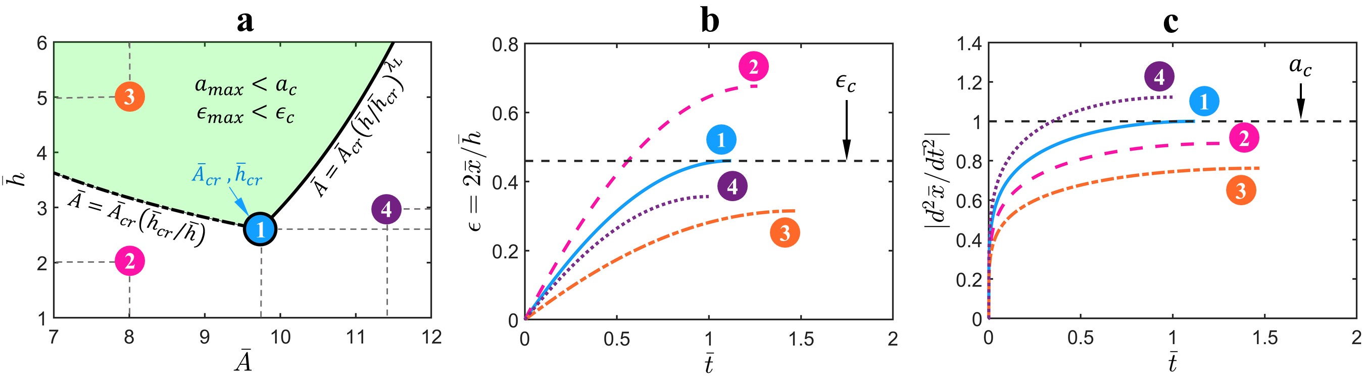
The above inequalities suggest that, to maintain the peak acceleration and maximum compression strain within the desired limits (Equation 16), the thickness of the foam must exceed a critical thickness , which depends on the material properties. Conversely, the cross-sectional area can vary within a range determined by the ratio and a critical area . For the limiting case of , must exactly be equal to . The flexibility in selecting and provides design freedom for addressing different challenging applications with geometric constraints on shock absorbers. In Figure 3(a), we illustrate such combinations in a shaded region bounded by the upper and lower limits of for an example and calculated from a certain set of material parameters (, , , , , ). All combinations of and that fall within the green-shaded region will ensure that the peak acceleration and peak compressive strain remain below the desired limits while the entire kinetic energy due to impact is absorbed by the foam. To validate this, we select four different combinations of and , as marked in Figure 3(a), for which we solve the time-domain differential equation (Equation 9). In Figure 3(b) and Figure 3(c), we plot strain and dimensionless acceleration, respectively, as functions of dimensionless time. At the critical point , the peak acceleration and the maximum strain exactly match the set upper limits and . For points (2) and (4), one of the conditions is not satisfied, whereas for point (3), which lies in the shaded region, both conditions are satisfied.
Thickness and mass minimization
As shown in the previous section, for a given set of material parameters , the thickness of the foam must be greater than the critical thickness , while the cross-sectional area can fall within a broad range defined by a lower and an upper limit (Equation 19) in order to limit peak acceleration and maximum compressive strain while entirely absorbing the kinetic energy of impact. These bounds on cross-sectional area depend on the ratio , such that the higher the ratio, the broader the range. Thus, any desired cross-sectional area within the permissible range can be achieved by proportionally scaling the thickness. We can use this property to identify an optimal set of material parameters that will minimize the thickness of a protective foam given a specific cross-sectional area, for absorbing a given kinetic energy of impact.
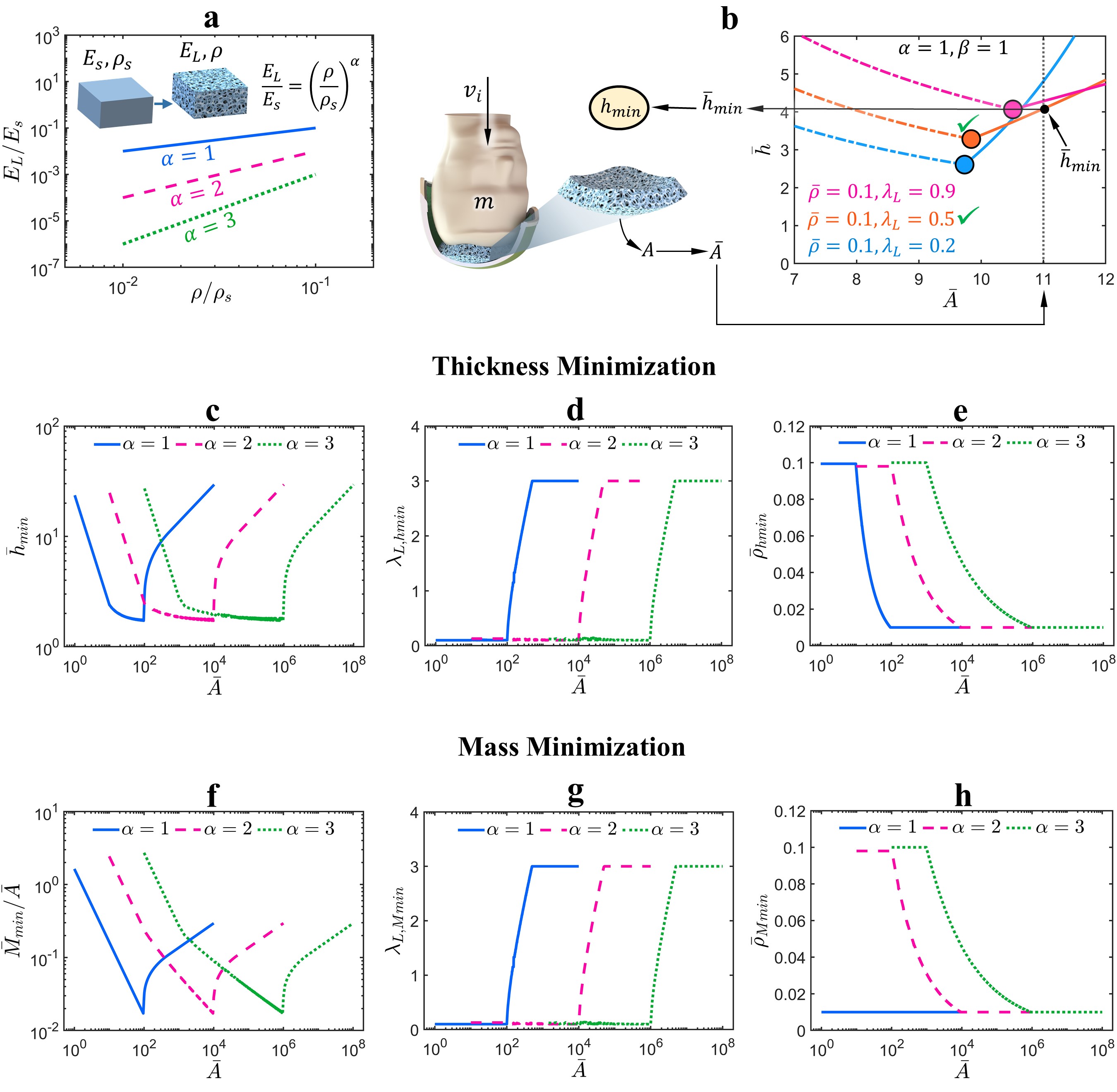
To this end, we consider a foam with density and modulus made of a solid material with density and modulus . As the relative modulus scales with relative density (Figure 4(a)), we explore three different scaling exponents that are commonly found in cellular materials literature: a linear scaling that is typically associated with a stretch-dominated deformation mechanism of the foam’s micro-structure [24], a quadratic scaling observed in bending-dominated deformation mechanisms [14], and cubic scaling which has been observed in foams with stochastic micro-structure [42]. Values of greater than 3 are exceedingly rare [43]. While certain efficient architectures demonstrate [10], values of less than have not been reported. We assume that the relative density varies between and , which is typical for open-cell foams [7] and approximately the range for which we measured the critical strain of various open-cell polymeric foams (Figure 2(b)). The measured critical strain follows a linear relationship with relative density, as shown in Figure 2(b). Additionally, we assume that ranges from (indicative of a highly sublinear stress-strain response resembling a Heaviside function) to (indicative of a highly nonlinear stress-strain response) (Figure 1(d)).
The workflow to achieve minimum thickness for a given cross-sectional area is illustrated in Figure 4(b) using an example of a head-helmet system undergoing a blunt impact, similar to that of a drop tower test for evaluating helmet performance. Here, represents the effective mass of the head-helmet system, while denotes the impact velocity. While the foam liner—often in combination with an additional soft layer for comfort—inside the helmet undergoes much more complex deformation [44], the direct impact shown in Figure 4(b) leads to axial compression of the foam liner that absorbs kinetic energy. For the cross-sectional area of the pad that experiences direct impact, the corresponding dimensionless area can be calculated using equation 8. The Figure 4(b) illustrates the process of obtaining the minimum thickness for a given ( in this example), indicated by a black dotted vertical line. Here, we consider three different values and their corresponding values (represented as colored dots in Figure 4(b)), which were obtained for , , and within the parameter space we considered (, , ). For each dot, when is scaled, the lower and upper limits of permissible are depicted by dashed and solid lines, respectively. The solid lines extend to our target , intersecting the vertical dotted line at different locations. Among the three dots, the orange dot corresponding to and results in the minimum thickness . This dimensionless minimum thickness can be converted to dimensional minimum thickness using the known parameters and to fabricate a compact foam pad (Equation 8). Let’s denote the and corresponding to the minimum thickness as and , respectively. The chosen energy absorbing foam must have a relative density equal to and a stress-strain response with to achieve the minimum thickness.
Similarly, all possible pairs of and within the range of material parameters (, , ) can be compared for a given to determine the absolute minimum thickness. In Figure 4(c), we plot the absolute minimum thickness as a function of obtained for material parameters , , and , varying within the range we assumed, while is fixed. As increases, counters and decreases initially to maintain the volume of the foam nearly constant for energy absorption, reaching a minimum, and then sharply rises to prevent the effective stiffness of the foam pad from becoming too large. The descending portion is governed by the constraint on set in equation 16, whereas the ascending portion is governed by equation 17 (see Figure S2 in SI). The two effects balance each other in the middle to generate a flat region with a nearly constant . For smaller cross-sectional areas , linear scaling results in the smallest thickness, whereas for , cubic scaling is better. This suggests that linear scaling results in a compact-sized foam pad for applications with space limitations in terms of area, such as a foam cartridge in landing struts (Figure 1(b)). On the other hand, cubic scaling performs better when more area has to be covered with foam, such as helmet liners and packaging applications.
Figure 4(d,e) show optimized parameters corresponding to the minimum thickness . A small value of initially leads to a lower value of (Equation 18). Therefore, it’s not surprising that for a smaller cross-sectional area, the thickness is minimized for . In contrast, for higher , the minimum thickness occurs for . Notice the power exponent in the upper limit of in equation 19, which allows for attaining significantly higher without scaling by a large amount. This demonstrates the utility of foams with a nonlinear stress-strain curve , which contradicts the conventionally held belief that foams should always exhibit a sublinear response with a plateau of nearly constant stress. The relative density on the other hand follows an opposite trend. A higher relative density for a small provides stiffness to the foam pad, whereas a low relative density, which results in a large critical strain , limits (equation 18) for large . It is worth mentioning that and are dimensionless; therefore, their magnitudes in Figure 4(c) are not to scale. Their magnitudes are meaningful only when converted back to their dimensional form using equation 8. Moreover, since we made our equations scale-free by rendering them dimensionless beforehand, any variation in the external factors such as , , and will only scale up or scale down and in Figure 4(c) without changing the trend of the curves. For example, setting a lower value of , which is akin to increasing the factor of safety, will make larger for a constant (Equation 8), affecting only the selected (Figure 4(c)) along with the associated and .
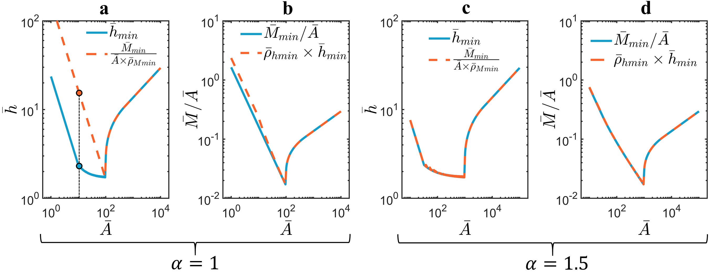
Minimizing thickness and making a foam pad compact in size doesn’t always guarantee minimum possible mass. The mass depends on both the volume and the relative density. The dimensionless mass can be calculated using the following equation
| (20) |
The above mass can be minimized and the resultant optimal material parameters can be obtained by using the similar methodology we implemented earlier for (Figure 4(b)). Since mass scales with area, we have plotted the minimum mass per unit area in Figure 4(f). The trend is similar to : linear scaling performs better for a small cross-section area, whereas cubic scaling is better when overlaying a larger area with foam. In Figure 4(g,h), we plot the optimized parameters and corresponding to minimum mass. For and , both and exactly match and respectively which suggest that both mass and thickness are simultaneously minimized. However, for , while still matches, the relative densities are different. remains constant at , which is the smallest relative density we considered. This occurs because for , the term vanishes from the critical mass, which is defined as follows:
| (21) |
While is a function of relative density, it is maximum for (Figure 2(b)), thus minimizes .
To summarize, a nonlinear scaling of relative modulus with relative density allows for the simultaneous minimization of both the mass and thickness of the foam. In contrast, for linear scaling , minimizing one disregards the other, not allowing both objectives to be simultaneously achieved. We can witness this by comparing the absolute minimum thickness with the thickness corresponding to the minimum mass, expressed as follows:
| (22) |
Figure 5(a) illustrates that for , minimizing the mass has unintentionally resulted in a much higher thickness. For example, at (black dotted line), the absolute minimum thickness is (on blue solid curve), while the thickness corresponding to when mass is minimized (ignoring thickness) is (orange dashed curve). Similarly, minimizing the thickness leads to a slightly higher mass, as shown in Figure 5(b). For , both mass and thickness are simultaneously minimized (Figure 5(c,d)).
Architected VACNT Foams
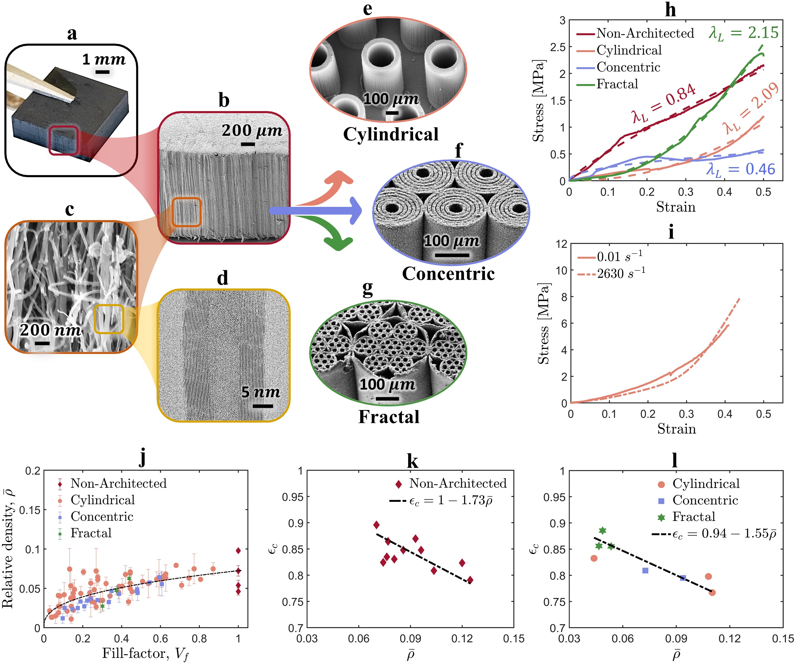
The underlying assumption behind the minimization problem we pursued in the previous section was that the material parameters, such as , , and , are independent of each other. In reality, they exhibit some inter-dependency, and not all possible combinations can occur, especially in stochastic polymeric and metallic foams. For example, a nonlinear stress-strain response (where ) is usually observed in foams with large relative densities. In contrast, architected foams offer versatility in the design space and allow independent tunability of different mechanical properties. The vertically aligned carbon nanotube (VACNT) foams with mesoscale architecture are particularly interesting because of their hierarchical structure that can be tailored to achieve broad range of properties. The non-architected VACNT foams themselves exhibit exceptional modulus and energy absorption comparable to metallic foams, while their densities, compressibility, and strain-recovery are similar to polymeric foams [25]. Moreover, unlike polymeric foams, which exhibit viscoelastic behavior and slowly recover from strain after compression, VACNT foams exhibit fast strain recovery, making them useful for countering repetitive impacts. These exceptional properties arise from a hierarchical structure with features across various length scales. Multi-walled CNTs (MWCNTs) at the nanoscale (Figure 6(d)), a random forest of entangled CNTs at the microscale (Figure 6(c)), and a structure of nominally vertically aligned CNTs at the mesoscale (Figure 6(b)) all culminate in a monolithic, seemingly solid foam at the macroscale (Figure 6(a)). We introduced an additional level of structural hierarchy at the mesoscale by synthesizing VACNTs on a photo-lithographically prepatterned silicon wafer substrate. We selectively deposit chromium in areas where we do not want CNTs to grow (the inverse of architecture), allowing growth only in the region defined by the architecture [23]. Figure 6 illustrates SEM images of three different mesoscale architectures: a hexagonally packed cylindrical architecture (Figure 6(e)), a concentric cylinder architecture (Figure 6(f)), and a self-similar fractal architecture (Figure 6(g)).
In our previous works on cylindrical and concentric-cylinder architected VACNT foams [31, 23], we reported tunability in density-dependent scaling, specific modulus, and relative density as functions of various architectural parameters [23, 31]. Furthermore, by increasing the gap between cylinders and thereby reducing lateral interactions between them, we demonstrated a transformation in the shape of the constitutive stress-strain curve from nonlinear to sublinear (see Figure 6(h)). Here, we introduce a self-similar fractal architecture that enhances interconnectivity between mesoscale cylinders at much lower relative densities, enabling higher specific energy absorption. We investigate fractal-architected samples and compare their properties with our previous cylindrical and concentric VACNT samples to identify optimal architectures for compact and lightweight shock absorbers.
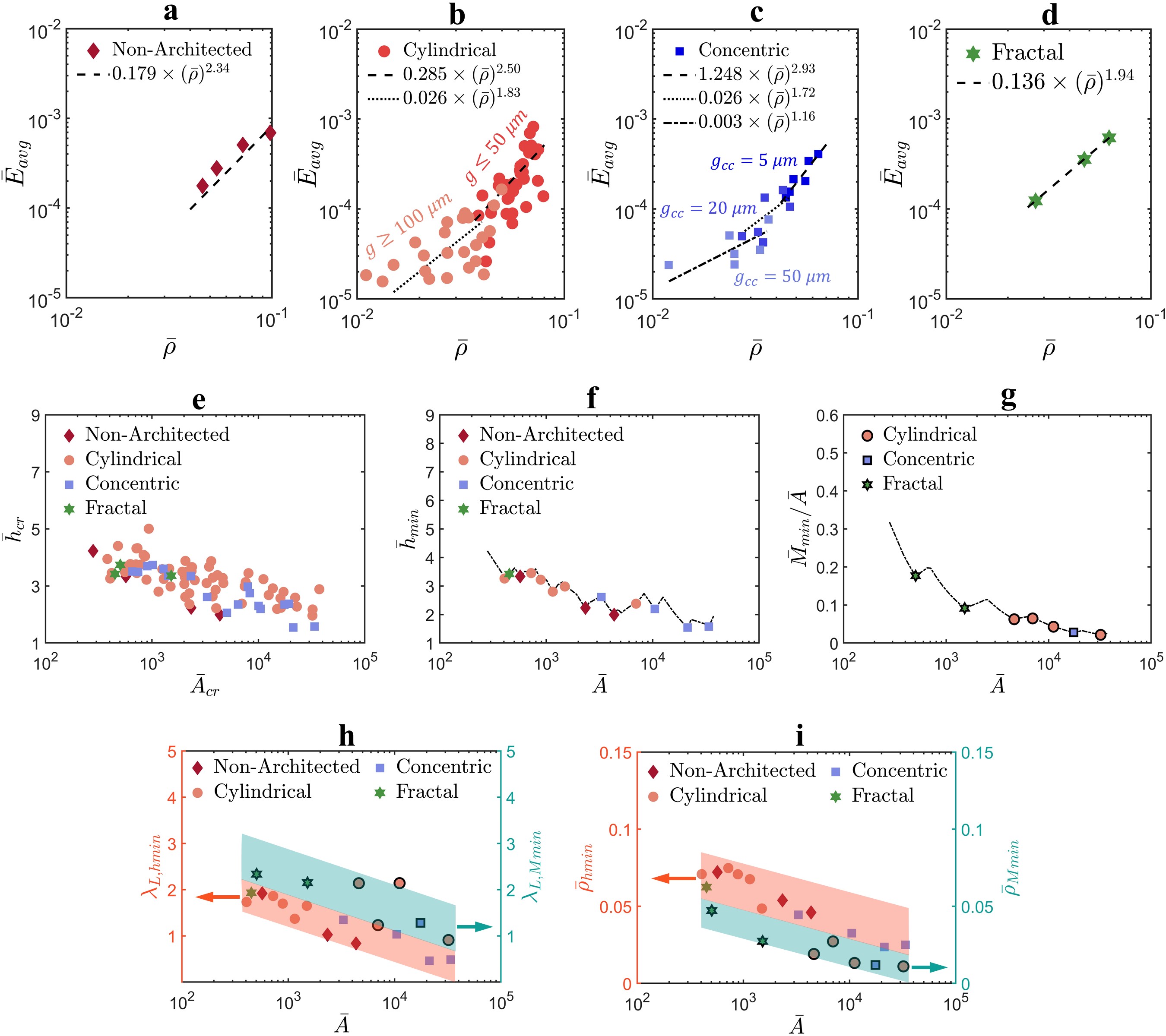
Figure 6(h) shows representative experimentally measured quasistatic (strain-rate of ) stress-strain responses of non-architected VACNT foam as well as architected foams, including the corresponding power law models (dashed curves). As shown, architected VACNT foams enhances the range of values of , which was limited to nearly linear for non-architected foams, to sublinear and nonlinear . The shape of the stress-strain curve or the value of depends on the specific architectural parameters that elicit specific deformation mechanism of cylinders within the architecture. For example, in concentric cylinder architecture (Figure 6(f)), a column buckling of cylinders with larger gap between the concentric cylinders results in a sublinear stress-strain curve, whereas a progressive shell buckling of cylinders with smaller gap results in a nonlinear stiffening stress-strain response [23]. Moreover, the stress-strain responses of both architected and non-architected VACNT foams are strain-rate independent (Figure 6(i)) up to very large strain rates [29, 45, 28]. In Figure 6, the stress-strain responses of a cylindrically architected VACNT foam we tested at quasistatic and dynamic strain rates, reveals almost no effect of strain rate. This strain-rate independence and the richness of material parameter space makes VACNT foams an ideal material system for us to demonstrate the effectiveness of our model in real materials.
We synthesized multiple samples in each architecture category by varying the dimensions of architectural features. For example, by varying the inner diameter , wall-thickness , and gap between the cylinders in cylindrically architected foams, we synthesized 60 different types of samples [31]. In concentric architecture, we varied the inner gap and the number of rings of concentric cylinders, resulting in a total of 18 samples [23]. For fractal architecture, we synthesized 3 types of samples with different orders of self-similarity (see Figure S3, S4 in SI). Moreover, we repeated the synthesis of each kind of sample three times and averaged the mechanical properties to account for any variability in the samples of a given architecture.
We calculated the relative density by dividing the bulk density of VACNT foams by the density of highly packed CNTs [46]. In Figure 6(j), we plotted the relative densities of all VACNT foams as a function of the fill-factor of the architectures (see SI for derived expressions of for different architectures). It is evident that the relative density is adjustable as a function of fill-factor and exhibits a wide range across samples, from to . As the fill-factor approaches , the relative density of architected VACNT foams asymptotically approaches the relative density of non-architected VACNT foams. Similar to polymeric foams in Figure 2(b), we measured the critical strain of both non-architected and architected VACNT foams using the energy absorption efficiency method [36]. For both types of foams, the critical strain varies linearly as a function of with a slope of , which is typically observed in crushable metallic foams [7].
We observe a wide range of density dependent scaling of elastic modulus among different architectures. In Figure 7(a,b,c,d), we plot average relative modulus of VACNT foams as a function of relative density, where is a dimensionless modulus calculated from the experimentally measured stress-strain response of VACNT foams. is a measure of the elastic energy stored in the foam during compression. Unlike , is normalized by , thus it scales more consistently with relative density (see SI for details). As a function of loading modulus and obtained from power-law fits, the expression of is given as follows
| (23) |
where, is the elastic modulus of highly densely packed CNTs () [47], is the peak compression strain applied while measuring the stress-strain response, and is the damping capacity—a ratio of hysteretic energy dissipated in the loading-unloading cycle divided by the area under the loading curve [23]. For non-architected and fractal-architected, the scaling is nonlinear with scaling exponent and respectively. However, for cylindrically-architected and concentric cylinder architectures, the scaling is tunable as a function of the external gap between the cylinders and the internal gap between the concentric cylinders respectively (see Figure S3, S4 in SI).
Using the measured material parameters we calculated dimensionless critical thickness and critical area which are plotted in Figure 7(e). To identify the VACNT foam samples that will result in minimum thickness, we implemented the framework that we demonstrated earlier in Figure 4(b). In the thickness minimization process, starting with samples, we were able to condense down to samples that will result in minimum thickness for a given area lying in the range shown in Figure 7(f). Similarly, we identified VACNT foam samples that will result in minimum mass for a given . For minimum mass, we were able to condense down to samples which all turned out to be architected VACNT foams, because of the comparatively large relative densities associated with non-architected VACNT foams. In Figure 7(h), we compare corresponding to minimum thickness with minimum mass . The data points corresponding to are plotted with black outline to distinguish from . The data points seem to form distinctive bands with forming a band of lower overall values compared to . In contrast, for relative density, values form a band of lower overall values compared to (Figure 7(i)). In summary, a higher and a sublinear are favourable to achieve minimum thickness whereas a smaller and a nonlinear are needed to achieve minimum mass.
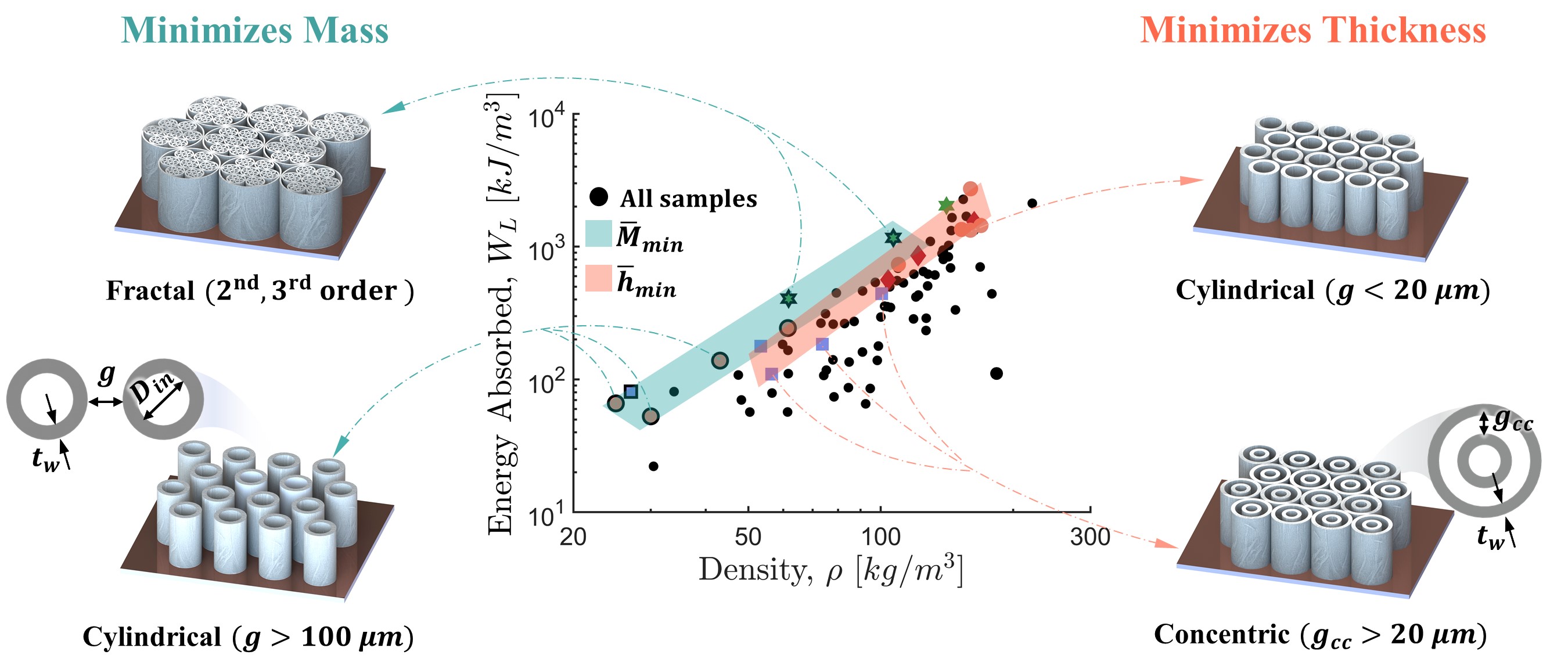
In Figure 8, we present a plot showing volumetric energy absorption versus density, where we have isolated the best-performing VACNT samples from a total of 85 samples. The samples that minimize thickness () are represented by colored markers, while data points for samples that minimize mass () are depicted with the same markers but with black borders. All other samples are shown using solid black dots.
The samples corresponding to and form two distinct bands in the top region of the scatter plot, demonstrating maximum energy absorption for a given density. The architectures corresponding to the majority of samples lying in these bands are illustrated along with their geometric design parameters. For , the samples include higher-order fractal ( and order) and sparsely packed cylindrically architected samples (with ) due to their low densities and high energy absorption capabilities. On the other hand, samples associated with include tightly packed cylindrical architected and non-architected samples due to their highest energy absorption. Additionally, sparsely packed concentric cylindrically architected foams are present due to their sublinear stress-strain response (Figure 7(h)) and consequently lower critical thickness () (see Equation 18). While a lot of samples, other than the optimal ones, lying in the band exhibit considerably high energy absorption at a given density, their are too large to minimize thickness.
In our theoretical calculations, we achieved simultaneously minimized thickness and mass for a large range of and varying independently. In VACNT foams, there seems to be a slight interdependence between and (Figure 7(h)), resulting in only one type of sample—a cylindrically architected foam with , , and that simultaneously minimizes both thickness and mass. However, using novel hierarchical graph network based machine-learning methods to design architectures can potentially result in a broadened parameter space, allowing for independent tunability of and . Such independent tunability can possibly lead to simultaneous thickness and mass minimization in various types of architectures.
Conclusion
In conclusion, our study highlights the pivotal role of a foam pad’s geometry in determining the mechanical performance. By employing a simplified kinematic model and dimensional analysis, we established constraints on the cross-sectional area and thickness of foam pads with known mechanical properties. These constraints ensure that both the maximum compressive strain within the foam and the maximum acceleration experienced by the protected object remain below desired limits. Using these constraints as a design framework, we identified the mechanical properties necessary for achieving the thinnest, lightest, or a combination of both in foam pads for a given cross-sectional area. Contrary to prevailing beliefs, our findings suggest that foams with stress-strain curves lacking a plateau of constant stress but instead exhibiting a nonlinear stress-strain response can lead to both thin and lightweight foam pads in many extreme protective applications. More specifically, we found that foams with a nonlinear stress-strain curve can outperform foams with a plateau-type stress-strain curve when constructing foam pads of large area, such as in helmet liners and packaging applications. Additionally, we also discover that foam materials with nonlinear density-dependent scaling of modulus can lead simultaneously lightweight and thin protective energy absorbers. Using our non-dimensional design framework, we demonstrate optimal designs in hierarchically architected VACNT foams with cylindrical, concentric cylindrical, and fractal architectures. Our generalized design framework can be applied to any architected and stochastic foams with known mechanical properties to design compact and lightweight energy absorbing pads for diverse protective applications by identifying the best-performing architectures from a multitude of options.
Methods
Synthesizing architected VACNT foams
To synthesize architected VACNT foams, we utilize silicon wafer substrates with predefined microscale patterns created using photolithography. First, we spin-coat a thick layer of photoresist (MICROPOSIT S1813) on a diameter p-type silicon wafer ( crystal orientation and thickness) at for and prebake it on a hot plate at for to remove any solvents. After spin-coating, we partially dice the wafer up to of its thickness into squares and expose it to ultraviolet light through a chrome/soda-lime photomask with predefined micropatterns (manufactured by Photo Sciences, Valencia, CA, USA). After exposure to UV light at for 8 seconds, we remove the unexposed photoresist in an MF321 developer bath for and then coat the wafer with a thin film of chromium at using a metal evaporator. To remove the remaining photoresist (UV exposed), we place the wafer in an acetone bath for , thereby leaving only chromium on the surface with the predefined architecture.
Mechanical characterization
To measure the stress-strain responses of VACNT foams and polymeric foams reported in this article, we performed ramp compression experiments using a commercial load frame, the Instron Electropulse E3000, equipped with a 5kN load cell. We compressed the samples at constant strain rate in a ramp waveform up to a strain exceeding the onset of densification strain to measure the critical strain and then unloaded at the same strain rate. To measure energy absorption and critical strain as functions of strain rate in polymeric foams, we varied the strain rates from to . To characterize the mass density, we measured the sample’s mass with a microbalance, measured its thickness with a micrometer gauge, and calculated its volume using the sample’s area and thickness.
Acknowledgement
This research is supported by the U.S. Office of Naval Research under PANTHER program award number N000142112044 through Dr. Timothy Bentley as well as the award number W911NF2010160 from the solid mechanics program of the U.S. Army Research Office through Dr. Denise Ford. The authors acknowledge the use of facilities and instrumentation at the Wisconsin Centers for Nanoscale Technology (WCNT) partially supported by the NSF through the University of Wisconsin Materials Research Science and Engineering Center (DMR-1720415). We thank Bhanugoban Maheswaran for performing the high strain rate compression experiments on the architected VACNT foam samples using a custom-built Kolsky bar apparatus. We also acknowledge Team Wendy for sending us their Zorbium soft and hard polyurethane foams to compare their mechanical properties with our VACNT foams.
Author Contributions
A.G. performed the theoretical analysis, performed the experiments on polymeric foams, analyzed the data, and prepared the figures. K.C. synthesized the VACNT foam samples and performed the quasistatic compression testing. R.T. conceived and supervised the project. A.G. and R.T. wrote the paper.
Competing Interests
The authors declare no competing interest.
Supplementary Information
Supplementary material related to this article can be found online
Code availability
Our MATLAB script for designing thin and lightweight shock absorber from a given set of available foam materials and known system parameters is available on https://github.com/ThevamaranLab/Shock-Absorber-Design.git
References
- [1] BJ Ramirez and V Gupta. Evaluation of novel temperature-stable viscoelastic polyurea foams as helmet liner materials. Materials & Design, 137:298–304, 2018.
- [2] FM Shuaeib, AMS Hamouda, SV Wong, RS Radin Umar, and MMH Megat Ahmed. A new motorcycle helmet liner material: The finite element simulation and design of experiment optimization. Materials & design, 28(1):182–195, 2007.
- [3] J Zhang and MF Ashby. Mechanical selection of foams and honeycombs used for packaging and energy absorption. Journal of Materials Science, 29:157–163, 1994.
- [4] Ke Li, X-L Gao, and Jun Wang. Dynamic crushing behavior of honeycomb structures with irregular cell shapes and non-uniform cell wall thickness. International Journal of Solids and Structures, 44(14-15):5003–5026, 2007.
- [5] AT Barnes, K Ravi-Chandar, S Kyriakides, and S Gaitanaros. Dynamic crushing of aluminum foams: Part i–experiments. International Journal of Solids and Structures, 51(9):1631–1645, 2014.
- [6] Meng Li, Zongquan Deng, Rongqiang Liu, and Hongwei Guo. Crashworthiness design optimisation of metal honeycomb energy absorber used in lunar lander. International Journal of crashworthiness, 16(4):411–419, 2011.
- [7] Lorna J Gibson. Cellular solids. Mrs Bulletin, 28(4):270–274, 2003.
- [8] Tobias A Schaedler and William B Carter. Architected cellular materials. Annual Review of Materials Research, 46:187–210, 2016.
- [9] Jens Bauer, Almut Schroer, Ruth Schwaiger, and Oliver Kraft. Approaching theoretical strength in glassy carbon nanolattices. Nature materials, 15(4):438–443, 2016.
- [10] Wen Chen, Seth Watts, Julie A Jackson, William L Smith, Daniel A Tortorelli, and Christopher M Spadaccini. Stiff isotropic lattices beyond the maxwell criterion. Science advances, 5(9):eaaw1937, 2019.
- [11] Cameron Crook, Jens Bauer, Anna Guell Izard, Cristine Santos de Oliveira, Juliana Martins de Souza e Silva, Jonathan B Berger, and Lorenzo Valdevit. Plate-nanolattices at the theoretical limit of stiffness and strength. Nature communications, 11(1):1579, 2020.
- [12] Li Zheng, Konstantinos Karapiperis, Siddhant Kumar, and Dennis M Kochmann. Unifying the design space and optimizing linear and nonlinear truss metamaterials by generative modeling. Nature Communications, 14(1):7563, 2023.
- [13] JB Berger, HNG Wadley, and RM McMeeking. Mechanical metamaterials at the theoretical limit of isotropic elastic stiffness. Nature, 543(7646):533–537, 2017.
- [14] Tobias A Schaedler, Alan J Jacobsen, Anna Torrents, Adam E Sorensen, Jie Lian, Julia R Greer, Lorenzo Valdevit, and Wiliam B Carter. Ultralight metallic microlattices. Science, 334(6058):962–965, 2011.
- [15] Xiaoyu Zheng, Howon Lee, Todd H Weisgraber, Maxim Shusteff, Joshua DeOtte, Eric B Duoss, Joshua D Kuntz, Monika M Biener, Qi Ge, Julie A Jackson, et al. Ultralight, ultrastiff mechanical metamaterials. Science, 344(6190):1373–1377, 2014.
- [16] Yujia Wang, Xuan Zhang, Zihe Li, Huajian Gao, and Xiaoyan Li. Achieving the theoretical limit of strength in shell-based carbon nanolattices. Proceedings of the National Academy of Sciences, 119(34):e2119536119, 2022.
- [17] Carlos M Portela, Bryce W Edwards, David Veysset, Yuchen Sun, Keith A Nelson, Dennis M Kochmann, and Julia R Greer. Supersonic impact resilience of nanoarchitected carbon. Nature Materials, 20(11):1491–1497, 2021.
- [18] Thomas Butruille, Joshua C Crone, and Carlos M Portela. Decoupling particle-impact dissipation mechanisms in 3d architected materials. Proceedings of the National Academy of Sciences, 121(6):e2313962121, 2024.
- [19] Jonghwan Suhr, Pushparaj Victor, Lijie Ci, Subbalakshmi Sreekala, Xianfeng Zhang, Omkaram Nalamasu, and Pulickel M Ajayan. Fatigue resistance of aligned carbon nanotube arrays under cyclic compression. Nature nanotechnology, 2(7):417–421, 2007.
- [20] Lucas R Meza, Alex J Zelhofer, Nigel Clarke, Arturo J Mateos, Dennis M Kochmann, and Julia R Greer. Resilient 3d hierarchical architected metamaterials. Proceedings of the National Academy of Sciences, 112(37):11502–11507, 2015.
- [21] Widianto P Moestopo, Sammy Shaker, Weiting Deng, and Julia R Greer. Knots are not for naught: Design, properties, and topology of hierarchical intertwined microarchitected materials. Science Advances, 9(10):eade6725, 2023.
- [22] Fady F Abayazid and Mazdak Ghajari. Viscoelastic circular cell honeycomb helmet liners for reducing head rotation and brain strain in oblique impacts. Materials & Design, page 112748, 2024.
- [23] Komal Chawla, Abhishek Gupta, and Ramathasan Thevamaran. Disrupting density-dependent property scaling in hierarchically architected foams. ACS nano, 17(11):10452–10461, 2023.
- [24] Michael F Ashby. The properties of foams and lattices. Philosophical Transactions of the Royal Society A: Mathematical, Physical and Engineering Sciences, 364(1838):15–30, 2006.
- [25] Anyuan Cao, Pamela L Dickrell, W Gregory Sawyer, Mehrdad N Ghasemi-Nejhad, and Pulickel M Ajayan. Super-compressible foamlike carbon nanotube films. Science, 310(5752):1307–1310, 2005.
- [26] Ramathasan Thevamaran, Eric R Meshot, and Chiara Daraio. Shock formation and rate effects in impacted carbon nanotube foams. Carbon, 84:390–398, 2015.
- [27] Komal Chawla, Jizhe Cai, Dakotah Thompson, and Ramathasan Thevamaran. Superior thermal transport properties of vertically aligned carbon nanotubes tailored through mesoscale architectures. Carbon, 216:118526, 2024.
- [28] Ming Xu, Don N Futaba, Takeo Yamada, Motoo Yumura, and Kenji Hata. Carbon nanotubes with temperature-invariant viscoelasticity from–196 to 1000 c. Science, 330(6009):1364–1368, 2010.
- [29] Jordan R Raney, Fernando Fraternali, and C Daraio. Rate-independent dissipation and loading direction effects in compressed carbon nanotube arrays. Nanotechnology, 24(25):255707, 2013.
- [30] Ludovica Lattanzi, Luigi De Nardo, Jordan R Raney, and Chiara Daraio. Geometry-induced mechanical properties of carbon nanotube foams. Advanced Engineering Materials, 16(8):1026–1031, 2014.
- [31] Komal Chawla, Abhishek Gupta, Abhijeet S Bhardwaj, and Ramathasan Thevamaran. Superior mechanical properties by exploiting size-effects and multiscale interactions in hierarchically architected foams. Extreme Mechanics Letters, 57:101899, 2022.
- [32] Chan Soo Ha, Desheng Yao, Zhenpeng Xu, Chenang Liu, Han Liu, Daniel Elkins, Matthew Kile, Vikram Deshpande, Zhenyu Kong, Mathieu Bauchy, et al. Rapid inverse design of metamaterials based on prescribed mechanical behavior through machine learning. Nature Communications, 14(1):5765, 2023.
- [33] Ke Liu, Rachel Sun, and Chiara Daraio. Growth rules for irregular architected materials with programmable properties. Science, 377(6609):975–981, 2022.
- [34] KC Rusch. Load-compression behavior of brittle foams. Journal of Applied Polymer Science, 14(5):1263–1276, 1970.
- [35] Amir Hassani, Ali Habibolahzadeh, and Hassan Bafti. Production of graded aluminum foams via powder space holder technique. Materials & Design, 40:510–515, 2012.
- [36] QM Li, I Magkiriadis, and John J Harrigan. Compressive strain at the onset of densification of cellular solids. Journal of cellular plastics, 42(5):371–392, 2006.
- [37] Julia R Greer and Vikram S Deshpande. Three-dimensional architected materials and structures: Design, fabrication, and mechanical behavior. MRS Bulletin, 44(10):750–757, 2019.
- [38] RR Cousins. A theory for the impact behavior of rate-dependent padding materials. Journal of applied polymer science, 20(10):2893–2903, 1976.
- [39] Kapil Bharadwaj Bhagavathula, Christopher S Meredith, Simon Ouellet, Sikhanda S Satapathy, Dan L Romanyk, and James D Hogan. Density, microstructure, and strain-rate effects on the compressive response of polyurethane foams. Experimental Mechanics, pages 1–15, 2022.
- [40] Rika Wright Carlsen, Alice Lux Fawzi, Yang Wan, Haneesh Kesari, and Christian Franck. A quantitative relationship between rotational head kinematics and brain tissue strain from a 2-d parametric finite element analysis. Brain Multiphysics, 2:100024, 2021.
- [41] Gordon S Mustin. Theory and practice of cushion design. Shock and Vibration Information Center, US Department of Defense, 1968.
- [42] Marcus A Worsley, Sergei O Kucheyev, Joe H Satcher, Alex V Hamza, and Theodore F Baumann. Mechanically robust and electrically conductive carbon nanotube foams. Applied Physics Letters, 94(7), 2009.
- [43] Joachim Gross, George W Scherer, Cynthia T Alviso, and Richard W Pekala. Elastic properties of crosslinked resorcinol-formaldehyde gels and aerogels. Journal of non-crystalline solids, 211(1-2):132–142, 1997.
- [44] B Maheswaran, K Chawla, and R Thevamaran. Mitigating oblique impacts by unraveling of buckled carbon nanotubes in helmet liners. Experimental Mechanics, 64(2):197–209, 2024.
- [45] Ludovica Lattanzi, Ramathasan Thevamaran, Luigi De Nardo, and Chiara Daraio. Dynamic behavior of vertically aligned carbon nanotube foams with patterned microstructure. Advanced Engineering Materials, 17(10):1470–1479, 2015.
- [46] Yeonsu Jung, Young Shik Cho, Jae Won Lee, Jun Young Oh, and Chong Rae Park. How can we make carbon nanotube yarn stronger? Composites Science and Technology, 166:95–108, 2018.
- [47] Siddhartha Pathak, Z Goknur Cambaz, Surya R Kalidindi, J Gregory Swadener, and Yury Gogotsi. Viscoelasticity and high buckling stress of dense carbon nanotube brushes. Carbon, 47(8):1969–1976, 2009.