A fully plasma based electron injector for a linear collider or XFEL
Abstract
We demonstrate through high-fidelity particle-in-cell simulations a simple approach for efficiently generating 20+ GeV electron beams with the necessary charge, energy spread, and emittance for use as the injector for an electron arm of a future linear collider or a next generation XFEL. The self-focusing of an unmatched, relatively low quality, drive beam results in self-injection by elongating the wakefield excited in the nonlinear blowout regime. Over pump depletion distances, the drive beam dynamics and self-loading from the injected beam leads to extremely high quality and high energy output beams. For plasma densities of , PIC simulation results indicate that self-injected beams with of charge can be accelerated to GeV energies with projected energy spreads, within the beam core, slice normalized emittances as low as , a peak normalized brightness , and energy transfer efficiencies .
pacs:
Plasma-based acceleration (PBA) Tajima and Dawson (1979); Chen et al. (1985) is a promising avenue for high gradient ( GV/m) acceleration Hogan et al. (2005); Blumenfeld et al. (2007); Leemans et al. (2014, 2006); Wang et al. (2013); Hafz et al. (2008); Litos et al. (2014); Adli et al. (2018); Steinke et al. (2016); Gonsalves et al. (2019) and high quality beam generation Chen et al. (2006); Oz et al. (2007); Pak et al. (2010); Xu et al. (2014a); Li et al. (2013); Yu et al. (2014); Xu et al. (2014b); Hidding et al. (2012); Bulanov et al. (1998); Suk et al. (2001); Fubiani et al. (2006); Xu et al. (2017); Martinez de la Ossa et al. (2017); xu2 (2022); Geddes et al. (2008); Gonsalves et al. (2011); Buck et al. (2013); Kalmykov et al. (2009); Xu et al. (2005); Dalichaouch et al. (2020); Xu et al. (2023); Li et al. (2022). PBA could thus be the mechanism to provide an injector for next generation x-ray light sources Barletta et al. (2010); Wang et al. (2021) or a future linear collider (LC). For an x-ray free-electron laser (XFEL), the generation of high power ( GW) requires GeV-class beams with high currents kA, low normalized emittances nm, and low energy spreads Barletta et al. (2010). These beams are typically characterized by high peak normalized brightnesses . Similarly, designs for TeV-class linear colliders also require low emittance, high charge particle beams to achieve high luminosities for e-e+ beam collisions at the interaction point (IP).
To produce the desired beams needed for LC and XFEL applications using PBA, numerous injection schemes Chen et al. (2006); Oz et al. (2007); Pak et al. (2010); Xu et al. (2014a); Li et al. (2013); Yu et al. (2014); Xu et al. (2014b); Hidding et al. (2012); Bulanov et al. (1998); Suk et al. (2001); Fubiani et al. (2006); Xu et al. (2017); Martinez de la Ossa et al. (2017); Geddes et al. (2008); Gonsalves et al. (2011); Buck et al. (2013); xu2 (2022); Kalmykov et al. (2009); Xu et al. (2005); Dalichaouch et al. (2020); Xu et al. (2023); Li et al. (2022) have been proposed in which plasma electrons are trapped and accelerated by nonlinear wakefields in the blowout regime. In these nonlinear wakes, plasma electrons are fully blown out by the intense fields of a laser pulse or particle beam driver creating an ion channel surrounded by a thin sheath of electrons. These sheath electrons can typically propagate at velocities near the speed of light at the rear of the channel and are therefore natural candidates to be trapped if the phase velocity, , can be controlled using a plasma density down ramp (DDR) Bulanov et al. (1998); Suk et al. (2001); Fubiani et al. (2006); Xu et al. (2017); Martinez de la Ossa et al. (2017); Geddes et al. (2008); Gonsalves et al. (2011); Buck et al. (2013); xu2 (2022), an evolving driver Kalmykov et al. (2009); Xu et al. (2005); Dalichaouch et al. (2020); Xu et al. (2023), or flying focus Li et al. (2022). Particle trapping induced by wakefield elongation has been shown to produce narrow beams with normalized emittances several orders of magnitude smaller than those of the drive beams Xu et al. (2017).
Maximizing energy gain and minimizing energy spread is challenging because it requires optimal beam loading Tzoufras et al. (2008, 2009); Dalichaouch et al. (2021); Xu et al. (2022) over pump depletion distances. While beams with nearly trapezoidal current profiles can be used to load constant wakefields Tzoufras et al. (2008, 2009); Dalichaouch et al. (2021); Xu et al. (2022), they can be difficult to realize through self-injection. Recently, low energy spread PBA schemes Kirchen et al. (2021); Liu et al. (2023) facilitated by a dynamic beam loading (DBL) effect in Bayesian-optimized or tri-plateau plasma density profiles Chiou and Katsouleas (1998); Liu et al. (2023) have attracted significant interest because they do not require such shaped bunches.
In this Letter, we present a novel approach to high energy, high brightness, low energy spread beam generation driven by DBL Chiou and Katsouleas (1998) in a self-injected, high efficiency, constant density PBA stage. An unmatched electron driver initially self-focuses its own wakefield leading to self-injection Dalichaouch et al. (2020). A DBL effect is subsequently induced by the plasma wake evolution over the pump depletion length. Using particle-in-cell (PIC) simulations and theory, we show that the wake evolution is caused by spot size expansion and dephasing of the driver due to pump depletion and betatron oscillations in the plasma. The electric field chirp within the trailing beam core decreases from positive (underloaded) to negative (overloaded) due to pump depletion, where is the co-moving coordinate. The cumulative effect is a trailing beam with small energy spread near pump depletion.
The physics of the DBL described here is different from those described in Refs. 41; 42; 43 that rely on dephasing in hollow channels or phase advancement from a discrete or continuous set of density plateaus within laser driven wakefields. For beam-driven wakes considered here, the wake transitions from underloaded to overloaded due to a decrease in the wake strength as the driver shape evolves due to pump depletion.
Based on PIC simulations using osiris Fonseca et al. (2002), we find that for parameters that may be possible at FACET II fac (2016) high quality trailing beams can be injected and efficiently accelerated to energies up to GeV with low normalized core energy spreads and high normalized brightnesses . The process is robust and works for Gaussian drivers with different durations . Simulation results presented in this Letter use the quasi-3D algorithm implemented in osiris Fonseca et al. (2002) with high resolution grids , , where is the plasma frequency. The algorithm expands the fields into azimuthal modes (m). In the full length simulations only the mode is kept while simulations of the initial injection and acceleration phase with up to 2 were carried out. A customized finite-difference solver and current deposit is used to reduce numerical effects due to injection Xu et al. (2013, 2020); Li et al. (2017).
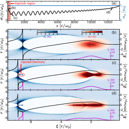
The key physics of this process is illustrated in Fig. 1. A 10 GeV () electron driver with a peak current of 51 kA () is initialized at the entrance of a constant density plasma (blue) with a focal spot size , , and Courant-Snyder (C-S) Lee (1999) parameters and , where is the plasma wavenumber, is the geometric emittance, and is the normalized emittance. For a plasma density of , these parameters correspond to an electron beam with charge , diffraction length , spot size , and beam length .
As the spot size of an electron drive beam decreases the ion channel elongates leading to self-injection Dalichaouch et al. (2020). This can be seen in Figs. 1(a)-(c). The spot size evolution of the driver depends on its betatron wavenumber and diffraction length , where is the focal spot size. Since the driver is not matched and , it is self-focused by the plasma ion channel, and the projected spot size, , oscillates over the length scale of the betatron wavelength as shown in Fig. 1(a). Wake expansion therefore occurs due to spot size focusing Dalichaouch et al. (2020) over , thereby reducing the phase velocity of the wake. As a result, energetic sheath electrons can be trapped and accelerated at the rear the ion channel as shown in Figs. 1(b)-(c).
While continues to oscillate after the first betatron oscillation, the amplitude of the subsequent oscillations is not as large. There is phase mixing between slices within the ion channel (rear) and slices at the head where blowout has not been fully established (smaller ). Thus injection is limited to the shaded region in Fig. 1(a).
The injected beam has a nearly trapezoidal current profile (purple) with high slice currents ( kA) in Figs. 1(b)-(d) within the beam core; however, it does not perfectly flatten the wakefield at [Fig. 1(b)]. As a result, a small positive electric field chirp is observed following injection. However, this chirp dynamically increases from positive (underloaded) to negative (overloaded) after the beam has propagated as seen in Figs. 1(c)-(d). As we will show, this DBL process is dictated by the drive beam energy. The wake therefore remains weakly underloaded over most of the acceleration and only becomes overloaded when the driver has significantly pump depleted ( energy loss). The injected beam is rapidly dechirped by the strong overloading (large negative ) in the final stage of acceleration [Fig. 1(d)]. As a result, the injected beam can be extracted with a low energy spread when the driver has nearly fully pump depleted at .
The DBL process illustrated in Fig. 1 is effectuated by two drive beam dynamics: (i) spot size defocusing and (ii) longitudinal dephasing. The driver spot size increases and current profile elongates as it loses energy and undergoes betatron oscillations [Fig. 1]. This alters the wake excitation and shape of the ion channel, , and, thus, the loading of the channel by the injected bunch.
We performed additional PIC simulations to obtain the unloaded wakefields by using the current density profile of the drive beam taken at and . A comparison of the results is shown in Fig. 2(a). The bubble trajectory, , crosses the axis slightly sooner at (see inset) due to spot size defocusing Dalichaouch et al. (2020). A slightly smaller blowout radius Lu et al. (2006a, b) is also produced due to the reduction in the driver peak current (purple); the double-peaked current profile arises because of slice dephasing around the driver centroid. These effects lead to a smaller at head of the injected beam and stronger loading from the space-charge force of the injected beam.
The transverse and longitudinal drive beam dynamics in Fig. 2(a) can be well-understood by examining the motion of the underlying beam electrons as they execute betatron oscillations in a uniform plasma and pump deplete. For a relativistic beam electron () propagating inside the ion channel, the conservation of implies the transverse coordinates follow Xu et al. (2014a); Zhao et al. (2020); Ariniello et al. (2022), where is the betatron phase, , , and subscript “i” denotes initial values.
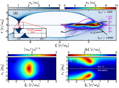
Defocusing is caused by the energy dependence of the betratron oscillations . As the beam electrons lose energy to the wake, their betatron oscillations increase in amplitude, leading to a larger projected spot size. In Fig. 2(b), it can be seen that the energy factor ranges from 2 to 3 for particles that have significantly pump depleted ( energy loss) at . These particles originate from positions where the decelerating field is largest (behind the beam centroid and inside the channel ). This pump depletion effect is the predominant reason for the increase in the slice spot size along the middle and rear of the beam in Fig. 2(a). While spot size expansion still occurs at the beam head due to diffraction, the effect is limited to a relatively small amount of charge ().
Longitudinal dephasing and slice mixing occurs as the beam electrons execute betatron oscillations. This is because the beam electrons do not travel in straight lines. Electrons oscillating with a transverse velocity, , slip backwards with . The total dephasing over a propagation distance can be well-approximated by (see Supplemental Material),
| (1) |
Eq. (1) is evaluated at in Fig. 2(c) and exhibits good agreement with obtained directly from the simulation results. Upon inspection of Eq. (1), it is evident that particles with low energies and large amplitudes dephase the most. Such particles are initially located behind the centroid near and dephase by as much as . This dephasing effect on these particles produces the double-peaked current profile in Fig. 2(a).
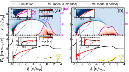
The drive beam evolution described above is inherently dictated by the beam energy . As the driver pump depletes, the change in the current density profile leads to a slightly smaller blowout radius and shorter wake wavelength when there is no beam load [Fig. 2(a)]. The evolution of the channel shape alters how it is loaded. This DBL process is illustrated in Fig. 3 using snapshots of the plasma wake, electric field, and drive beam energy distribution at different stages of acceleration. The wakefield at each stage is fully described by the wake potential where and are the scalar and axial vector potential, respectively. Beam loading effects are analyzed using the multi-sheath model Dalichaouch et al. (2021). Inside the channel, the axial potential , which is used to calculate and . Details on the model parameters and equations are provided in the Supplemental Material.
At , the wakefield remains slightly underloaded with a positive chirp () along the injected bunch [Fig. 3(a)]. The ion channel shape has not changed significantly since the termination of injection. However, after significant pump depletion (half the beam has lost most of its energy), the wakefield becomes overloaded () at [Fig. 3(b)]. The shift to overloaded is attributed to the evolution of the ion channel: is now smaller at the head of the injected beam. The innermost sheath electron thus feels a stronger space-charge force, , as it passes the injected beam thereby reducing . As the stronger loading modifies the electron momenta, it also alters the wake potential which obeys the relationship Mora and Antonsen (1997); Dalichaouch et al. (2021). Based on PIC simulation results, we find that the minimum wake potential increases from to from to . Due to these effects, the slope Mora and Antonsen (1997) is significantly reduced at the rear of the channel. The resulting electric field therefore decreases from the rear to the front of the injected beam. The negative chirp is reproduced by the multi-sheath model (solid red) using in Fig. 3(b).
Fig. 3 shows that the electric field slope along the injected beam decreases from positive to negative as the driver pump depletes. As a result, the average slope over the acceleration length decreases within the beam core as approaches the pump depletion length, . In Fig. 4(a), we plot the average energy , absolute energy spread , and normalized energy spread of the injected beam core as a function of propagation distance. Initially, and decrease as the underloaded wakefield reduces the initial positive energy chirp of the beam following injection Xu et al. (2017). A global minimum in therefore occurs near and subsequently increases as the beam acquires a negative energy chirp from the underloaded wakefield. It begins to plateau around and then decreases as the shifts from underloaded to overloaded. After , the residual energy chirp rapidly reduces to sub-0.1 GeV and deviates significantly from the linear trendline of . This leads to approaching a global minimum at .
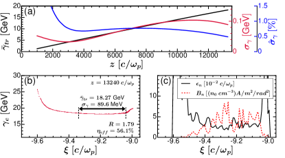
Figs. 4(b)-(c) show the final energy distribution and beam slice parameters at . Within the core of the beam (dashed black), we find an average energy of GeV, a projected energy spread of MeV (0.49%), and slice energy spreads as low as MeV. Defining the transformer ratio, , as the ratio of the average energy gain of the injected beam core to the maximum energy loss of the driver, we find max. A significant amount of charge is injected, corresponding to nC for . A high transfer efficiency from the drive to trailing bunch is achieved. Normalized slice emittances (solid black) as low as () and normalized brightnesses (dashed red) as high as are observed within the beam core. Additional simulations carried out using drivers with longer diffraction lengths up to indicate that similar beams with core energies GeV and core energy spreads are produced. Simulations with out to found the injection and initial acceleration was very similar.
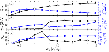
Similar results are obtained for drivers with different durations, , as seen in Fig. 5. A clear transition to optimal beam loading occurs for due to higher slice currents driving full rotation of from negative to positive. For these parameters, the simulation results indicate that the injected beams can be accelerated to energies ranging from – GeV with low core energy spreads . In Fig. 5(c), high transfer efficiencies (solid blue) in excess of and peak brightnesses (solid black) on the order of are also observed for . For plasma densities of , the results indicate that peak brightnesses on the order of can be achieved. These high-energy and bright beams may provide compact XFELs in the hundreds of keV photon range.
This work was supported by US NSF grant No. 2108970 and US DOE grant No. DE-SC0010064. The simulations were performed on the National Energy Research Scientific Computing Center (NERSC) and Hoffman2 at UCLA.
References
- Tajima and Dawson (1979) T. Tajima and J. M. Dawson, Phys. Rev. Lett. 43, 267 (1979).
- Chen et al. (1985) P. Chen, J. M. Dawson, R. W. Huff, and T. Katsouleas, Phys. Rev. Lett. 54, 693 (1985).
- Hogan et al. (2005) M. J. Hogan, C. D. Barnes, C. E. Clayton, F. J. Decker, S. Deng, P. Emma, C. Huang, R. H. Iverson, D. K. Johnson, C. Joshi, T. Katsouleas, P. Krejcik, W. Lu, K. A. Marsh, W. B. Mori, P. Muggli, C. L. O’Connell, E. Oz, R. H. Siemann, and D. Walz, Phys. Rev. Lett. 95, 054802 (2005).
- Blumenfeld et al. (2007) I. Blumenfeld, C. E. Clayton, F.-J. Decker, M. J. Hogan, C. Huang, R. Ischebeck, R. Iverson, C. Joshi, T. Katsouleas, N. Kirby, W. Lu, K. A. Marsh, W. B. Mori, P. Muggli, E. Oz, R. H. Siemann, D. Walz, and M. Zhou, Nature 445, 741 EP (2007).
- Leemans et al. (2014) W. P. Leemans, A. J. Gonsalves, H.-S. Mao, K. Nakamura, C. Benedetti, C. B. Schroeder, C. Tóth, J. Daniels, D. E. Mittelberger, S. S. Bulanov, J.-L. Vay, C. G. R. Geddes, and E. Esarey, Phys. Rev. Lett. 113, 245002 (2014).
- Leemans et al. (2006) W. P. Leemans, B. Nagler, A. J. Gonsalves, C. Tóth, K. Nakamura, C. G. R. Geddes, E. Esarey, C. B. Schroeder, and S. M. Hooker, Nature Physics 2, 696 EP (2006).
- Wang et al. (2013) X. Wang, R. Zgadzaj, N. Fazel, Z. Li, S. A. Yi, X. Zhang, W. Henderson, Y. Y. Chang, R. Korzekwa, H. E. Tsai, C. H. Pai, H. Quevedo, G. Dyer, E. Gaul, M. Martinez, A. C. Bernstein, T. Borger, M. Spinks, M. Donovan, V. Khudik, G. Shvets, T. Ditmire, and M. C. Downer, Nature Communications 4, 1988 EP (2013).
- Hafz et al. (2008) N. A. M. Hafz, T. M. Jeong, I. W. Choi, S. K. Lee, K. H. Pae, V. V. Kulagin, J. H. Sung, T. J. Yu, K.-H. Hong, T. Hosokai, J. R. Cary, D.-K. Ko, and J. Lee, Nature Photonics 2, 571 EP (2008).
- Litos et al. (2014) M. Litos, E. Adli, W. An, C. Clarke, C. Clayton, S. Corde, J. Delahaye, R. England, A. Fisher, J. Frederico, et al., Nature 515, 92 (2014).
- Adli et al. (2018) E. Adli, A. Ahuja, O. Apsimon, R. Apsimon, A.-M. Bachmann, D. Barrientos, F. Batsch, J. Bauche, V. B. Olsen, M. Bernardini, et al., Nature 561, 363 (2018).
- Steinke et al. (2016) S. Steinke, J. Van Tilborg, C. Benedetti, C. Geddes, C. Schroeder, J. Daniels, K. Swanson, A. Gonsalves, K. Nakamura, N. Matlis, et al., Nature 530, 190 (2016).
- Gonsalves et al. (2019) A. J. Gonsalves, K. Nakamura, J. Daniels, C. Benedetti, C. Pieronek, T. C. H. de Raadt, S. Steinke, J. H. Bin, S. S. Bulanov, J. van Tilborg, C. G. R. Geddes, C. B. Schroeder, C. Tóth, E. Esarey, K. Swanson, L. Fan-Chiang, G. Bagdasarov, N. Bobrova, V. Gasilov, G. Korn, P. Sasorov, and W. P. Leemans, Phys. Rev. Lett. 122, 084801 (2019).
- Chen et al. (2006) M. Chen, Z.-M. Sheng, Y.-Y. Ma, and J. Zhang, Journal of Applied Physics 99, 056109 (2006).
- Oz et al. (2007) E. Oz et al., Phys. Rev. Lett. 98, 084801 (2007).
- Pak et al. (2010) A. Pak, K. A. Marsh, S. F. Martins, W. Lu, W. B. Mori, and C. Joshi, Phys. Rev. Lett. 104, 025003 (2010).
- Xu et al. (2014a) X. L. Xu et al., Phys. Rev. Lett. 112, 035003 (2014a).
- Li et al. (2013) F. Li et al., Phys. Rev. Lett. 111, 015003 (2013).
- Yu et al. (2014) L.-L. Yu, E. Esarey, C. B. Schroeder, J.-L. Vay, C. Benedetti, C. G. R. Geddes, M. Chen, and W. P. Leemans, Phys. Rev. Lett. 112, 125001 (2014).
- Xu et al. (2014b) X. L. Xu, Y. P. Wu, C. J. Zhang, F. Li, Y. Wan, J. F. Hua, C.-H. Pai, W. Lu, P. Yu, C. Joshi, and W. B. Mori, Phys. Rev. ST Accel. Beams 17, 061301 (2014b).
- Hidding et al. (2012) B. Hidding, G. Pretzler, J. B. Rosenzweig, T. Königstein, D. Schiller, and D. L. Bruhwiler, Phys. Rev. Lett. 108, 035001 (2012).
- Bulanov et al. (1998) S. Bulanov, N. Naumova, F. Pegoraro, and J. Sakai, Phys. Rev. E 58, R5257 (1998).
- Suk et al. (2001) H. Suk, N. Barov, J. B. Rosenzweig, and E. Esarey, Phys. Rev. Lett. 86, 1011 (2001).
- Fubiani et al. (2006) G. Fubiani, E. Esarey, C. B. Schroeder, and W. P. Leemans, Phys. Rev. E 73, 026402 (2006).
- Xu et al. (2017) X. L. Xu, F. Li, W. An, T. N. Dalichaouch, P. Yu, W. Lu, C. Joshi, and W. B. Mori, Phys. Rev. Accel. Beams 20, 111303 (2017).
- Martinez de la Ossa et al. (2017) A. Martinez de la Ossa, Z. Hu, M. J. V. Streeter, T. J. Mehrling, O. Kononenko, B. Sheeran, and J. Osterhoff, Phys. Rev. Accel. Beams 20, 091301 (2017).
- xu2 (2022) Nature Communications 13, 3364 (2022).
- Geddes et al. (2008) C. G. R. Geddes, K. Nakamura, G. R. Plateau, C. Toth, E. Cormier-Michel, E. Esarey, C. B. Schroeder, J. R. Cary, and W. P. Leemans, Phys. Rev. Lett. 100, 215004 (2008).
- Gonsalves et al. (2011) A. J. Gonsalves, K. Nakamura, C. Lin, D. Panasenko, S. Shiraishi, T. Sokollik, C. Benedetti, C. B. Schroeder, C. G. R. Geddes, J. van Tilborg, J. Osterhoff, E. Esarey, C. Toth, and W. P. Leemans, Nature Physics 7, 862 EP (2011).
- Buck et al. (2013) A. Buck, J. Wenz, J. Xu, K. Khrennikov, K. Schmid, M. Heigoldt, J. M. Mikhailova, M. Geissler, B. Shen, F. Krausz, S. Karsch, and L. Veisz, Phys. Rev. Lett. 110, 185006 (2013).
- Kalmykov et al. (2009) S. Kalmykov, S. A. Yi, V. Khudik, and G. Shvets, Phys. Rev. Lett. 103, 135004 (2009).
- Xu et al. (2005) H. Xu, W. Yu, P. Lu, V. K. Senecha, F. He, B. Shen, L. Qian, R. Li, and Z. Xu, Physics of Plasmas 12, 013105 (2005).
- Dalichaouch et al. (2020) T. N. Dalichaouch, X. L. Xu, F. Li, A. Tableman, F. S. Tsung, W. An, and W. B. Mori, Phys. Rev. Accel. Beams 23, 021304 (2020).
- Xu et al. (2023) X. Xu, T. N. Dalichaouch, J. Liu, Q. Ma, J. Pierce, K. Miller, X. Yan, and W. B. Mori, Phys. Rev. Accel. Beams 26, 111302 (2023).
- Li et al. (2022) F. Li, T. N. Dalichaouch, J. R. Pierce, X. Xu, F. S. Tsung, W. Lu, C. Joshi, and W. B. Mori, Phys. Rev. Lett. 128, 174803 (2022).
- Barletta et al. (2010) W. Barletta et al., Nuclear Instruments and Methods in Physics Research Section A: Accelerators, Spectrometers, Detectors and Associated Equipment 618, 69 (2010).
- Wang et al. (2021) W. Wang, K. Feng, L. Ke, C. Yu, Y. Xu, R. Qi, Y. Chen, Z. Qin, Z. Zhang, M. Fang, J. Liu, K. Jiang, H. Wang, C. Wang, X. Yang, F. Wu, Y. Leng, J. Liu, R. Li, and Z. Xu, Nature 595, 516 (2021).
- Tzoufras et al. (2008) M. Tzoufras, W. Lu, F. S. Tsung, C. Huang, W. B. Mori, T. Katsouleas, J. Vieira, R. A. Fonseca, and L. O. Silva, Phys. Rev. Lett. 101, 145002 (2008).
- Tzoufras et al. (2009) M. Tzoufras, W. Lu, F. S. Tsung, C. Huang, W. B. Mori, T. Katsouleas, J. Vieira, R. A. Fonseca, and L. O. Silva, Physics of Plasmas 16, 056705 (2009), https://doi.org/10.1063/1.3118628 .
- Dalichaouch et al. (2021) T. N. Dalichaouch, X. L. Xu, A. Tableman, F. Li, F. S. Tsung, and W. B. Mori, Physics of Plasmas 28, 063103 (2021), https://doi.org/10.1063/5.0051282 .
- Xu et al. (2022) X. Xu, F. Li, F. S. Tsung, K. Miller, V. Yakimenko, M. J. Hogan, C. Joshi, and W. B. Mori, Nature Communications 13, 3364 (2022).
- Kirchen et al. (2021) M. Kirchen, S. Jalas, P. Messner, P. Winkler, T. Eichner, L. Hübner, T. Hülsenbusch, L. Jeppe, T. Parikh, M. Schnepp, and A. R. Maier, Phys. Rev. Lett. 126, 174801 (2021).
- Liu et al. (2023) S. Liu, F. Li, S. Zhou, J. Hua, W. B. Mori, C. Joshi, and W. Lu, “A scalable, high-efficiency, low-energy-spread, laser wakefield accelerator using a tri-plateau plasma channel,” (2023), arXiv:2311.14269 [physics.acc-ph] .
- Chiou and Katsouleas (1998) T. C. Chiou and T. Katsouleas, Phys. Rev. Lett. 81, 3411 (1998).
- Fonseca et al. (2002) R. A. Fonseca, L. O. Silva, F. S. Tsung, V. K. Decyk, W. Lu, C. Ren, W. B. Mori, S. Deng, S. Lee, T. Katsouleas, and J. C. Adam, in Proceedings of the International Conference on Computational Science-Part III, ICCS ?02 (Springer-Verlag, Berlin, Heidelberg, 2002) p. 342?351.
- fac (2016) FACET-II Technical Design Report No. SLAC-R-1072 (2016).
- Xu et al. (2013) X. Xu, P. Yu, S. F. Martins, F. S. Tsung, V. K. Decyk, J. Vieira, R. A. Fonseca, W. Lu, L. O. Silva, and W. B. Mori, Computer Physics Communications 184, 2503 (2013).
- Xu et al. (2020) X. Xu, F. Li, F. S. Tsung, T. N. Dalichaouch, W. An, H. Wen, V. K. Decyk, R. A. Fonseca, M. J. Hogan, and W. B. Mori, Journal of Computational Physics 413, 109451 (2020).
- Li et al. (2017) F. Li, P. Yu, X. Xu, F. Fiuza, V. K. Decyk, T. Dalichaouch, A. Davidson, A. Tableman, W. An, F. S. Tsung, R. A. Fonseca, W. Lu, and W. B. Mori, Computer Physics Communications 214, 6 (2017).
- Lee (1999) S. Y. Lee, Accelerator Physics (WORLD SCIENTIFIC, 1999) https://www.worldscientific.com/doi/pdf/10.1142/3977 .
- Lu et al. (2006a) W. Lu, C. Huang, M. Zhou, M. Tzoufras, F. S. Tsung, W. B. Mori, and T. Katsouleas, Physics of Plasmas 13, 056709 (2006a).
- Lu et al. (2006b) W. Lu, C. Huang, M. Zhou, W. B. Mori, and T. Katsouleas, Phys. Rev. Lett. 96, 165002 (2006b).
- Zhao et al. (2020) Y. Zhao, W. An, X. Xu, F. Li, L. Hildebrand, M. J. Hogan, V. Yakimenko, C. Joshi, and W. B. Mori, Phys. Rev. Accel. Beams 23, 011302 (2020).
- Ariniello et al. (2022) R. Ariniello, C. E. Doss, V. Lee, C. Hansel, J. R. Cary, and M. D. Litos, Phys. Rev. Res. 4, 043120 (2022).
- Mora and Antonsen (1997) P. Mora and T. M. Antonsen, Jr., Physics of Plasmas 4, 217 (1997), https://doi.org/10.1063/1.872134 .