Magnetotransport Properties of Ferromagnetic/Antiferromagnetic Superlattices: Probing the role of induced magnetization in antiferromagnetic layer
Abstract
We investigate the magnetic and transport properties of the (LSMO)/ (PCMO) like ferromagnetic/antiferromagnetic superlattices in three dimensions using a two orbitals double exchange model incorporating the Jahn-Teller lattice distortions, superexchange interactions and long-range Coulomb interactions. In our simulations we primarily focus on periodic arrangement of planes of ferromagnetic LSMO and planes of antiferromagnetic PCMO manganites, and set + = 10. The induced ferromagnetic correlations in the parent PCMO layer decreases monotonically with increasing the PCMO layer width at high temperatures for both half-doping () and off-half-doping () scenarios. As we decrease the temperature further the induced ferromagnetic moments in PCMO layer disappears or decreases considerably at half-doping due to the onset of charge ordering in antiferromagnetic PCMO layers. Overall, the magnetization in PCMO layer decreases at low temperatures and the metal-insulator transition temperature of the LSMO/PCMO superlattices increases with increase of the PCMO layer width , similar to the experiments. On the other hand, at off-half-doping, the induced ferromagnetic moment survives even at low temperatures due to weakened charge ordering in PCMO layer and interestingly, varies nonmonotonically with PCMO layer width, in agreement with experiments. The nonmonotonic trend of the conductivity of the superlattice with increase of the PCMO layer width shows an one-to-one correspondence between conductivity of the superlattice and the induced ferromagnetic moments in the PCMO layer. We highlight the key role of induced ferromagnetic moment in PCMO layer in analyzing the magnetotransport properties of the LSMO/PCMO superlattices.
I Introduction
The surfaces and interfaces of artificially layered complex oxide heterostructures frequently display new properties Huang ; Ngai ; Hellman ; Chen ; Hwang that differ significantly from their bulk counterparts Ohtomo ; Takahashi ; Zheng , arising mainly due to abrupt changes in electronic density Garcia ; Gibert ; Ohtomo1 ; Hoffman , lowering of the crystal symmetry Hwang , growth-induced strain and/or defects Kourkoutis at the interfaces. Surprisingly, the physics that emerges at the interfaces are in some cases absent in the bulk constituent materials Ohtomo ; Takahashi ; Zheng . For example, an unexpected ferromagnetic metallic phase is realized at the interface of Mott-insulator and the band insulator Ohtomo2 ; Seo . This conducting magnetic phase that emerges at the interface is due to the electronic charge transfer from the Ti- band of to the Ti- band of Okamoto . Overall, the induced magnetism at the interface controls the magnetotransport properties of the superlattice system Bruno . Interfacial magnetism Brinkman ; Koida and superconductivity Reyren ; Gozar (or even their co-existence Dikin ), exchange bias Yu ; Gibert1 ; Zhou , magnetoelectric coupling Zubko ; Liang ; Bhoi ; Gupta ; Lawes are few other interesting examples of the unique phenomena that materializes at the interfaces in oxide heterostructures. These unusual phenomena are of great technological importance Mannhart ; Brivio ; Yajima ; Shen ; Ramesh , for instance in designing next generation spintronic devices Zutic ; Tsymbal ; Teresa ; Ziese ; Bibes .
Among various complex oxides, doped rare-earth based perovskite manganites (R1-xAxMnO3 where R and A represents the rare-earth and alkaline-earth elements, respectively) Dagotto are believed to be among the strong candidates for various practical applications Panagio ; Krivorotov ; Julliere ; Salafranca ; Sun ; Jo , such as spin-valves Julliere ; Salafranca , magnetic tunnel junctions Sun ; Jo and magnetic sensors Bibes1 . These Mn-based oxide compounds exhibit a myriad of phases, e.g., ferromagnetism (FM), antiferromagnetism (AF), charge-ordered (CO), orbital ordered (OO) phases, manifested mainly by the strong correlation among the spin, charge, orbital and lattice degrees of freedom Tokura ; Tokura1 ; Dagotto1 ; Kajimoto . The ground state phase can be tuned by using different combination of R and A elements and their concentration Dagotto2 ; Chatterji . Phase competition occurs at the boundary of various phases and give rise to colossal magnetoresistance like effects near optimal doping Jin ; Xiong . In other words, engineering electronic phase separation can be used as an effective tool to enhance the magnetoresistance Uehara ; Fath ; Pradhan3 .
Electronic phase separation, which represents the coexistence of two competing phases- for example an antiferromagnetic insulating (AF-I) phase with a ferromagnetic metallic (FM-M) phase is one of the interesting property in manganites Moreo ; Khomskii ; Simon . Upon application of a magnetic field, the AF-I phase diminishes whereas the FM-M phase grows in size Helmolt ; Tokura ; Tokura1 , giving rise to the intriguing phenomena- known as magnetoresistance Helmolt ; Tokura ; Tokura1 ; Jin ; Xiong . Generally, half doped ( = 0.5) manganite systems depicts charge ordered antiferromagnetic phase which are highly insulating in nature Tomoika ; Kuwahara . Nanoscale electronic phase separation can be achieved in these kind of charge ordered antiferromagnetic insulating systems by introducing ferromagnetic phase fraction as follows: (i) by doping the system away from = 0.5 Kajimoto ; Simon ; or (ii) by artificially making FM/AF heterostructures Nieb1 ; Nieb2 and thus inducing a ferromagnetic metallic clusters in an antiferromagnetic manganite. That is to say, the phase competition can be engineered by preparing superlattices of two different manganites where competition between the two phases across the interfaces plays a vital role. Recently, a great amount of effort has been devoted to engineer the electronic and magnetic phase competition in manganite heterostructures.
The phase competition is mostly limited to few atomic layers near the interface. For example, a ferromagnetic phase appears only at the interface in the manganite superlattice Bhattacharya ; Adamo due to electronic phase competition although the individual LMO and SMO are antiferromagnetic with Neel temperature 140 K and 260 K, respectively. The total system turns out to be ferromagnetic for . A metal-insulator transition occurs for . Resulting ferromagnetic metallic state at the interface is analogue to the solid solution . The magnetic properties are largely modified at the interfaces due to the charge transfer across the interface Zhong ; Zhou ; Gibert . On the other hand, a C-type AF phase is observed in superlattice May for n = 1 and n = 2 which is equivalent to the properties of the bulk . Interestingly, the antiferromagnetic Neel temperature increases by in superlattices as compared to the solid solution. In general, phase competition emerging from the charge transfer from LMO to SMO at the interface for n = 1 and n = 2 guides the LMO/SMO superlattice systems to retain the magnetic phases which are obtained in the counterpart solid solution.
The synthetically created nanoscale electronic phase competition is also reported in manganite superlattices prepared using ferromagnetic manganites (like and ) and charged ordered antiferromagnetic insulating manganites (like ) Mukhopadhyay ; Li The charge transfer across the interface from LSMO to PCMO induces magnetization in the antiferromagnetic PCMO layers. Amount of these induced ferromagnetic moments depend on the width of the PCMO layer. Interestingly, it was observed that the induced magnetization depicts a nonmonotonic behavior with variation of the PCMO layer thickness Nieb1 ; Nieb2 and the maximum magnetization is obtained at a thickness comparable to the size of ferromagnetic nanoclusters as evidenced from polarized neutron reflectivity Saurel ; Mercone . In other words, when the dimension of the induced ferromagnetic nanoclusters and the thickness of the PCMO layer are comparable to each other one observes the maximum number of induced ferromagnetic nanoclusters in PCMO layers. In an small external magnetic field, the magnetization of induced ferromagnetic nanoclusters in PCMO layer orient along the field direction, resulting in a decrease in spin scattering at the interfaces. So the mobility of the carriers and also the conductivity of the system increases due to these induced ferromagnetic nanoclusters. In fact, the magnetoresistance of the system follows the same nonmonotonic behavior of the induced magnetization with the PCMO layer width Nieb2 . So, overall the width of the PCMO layer serves as a key parameter to tune the magnetoresistance in LSMO/PCMO or LCMO/PCMO superlattices Mukhopadhyay ; Li ; Cheng and thus making the system technologically important for applications in magnetic field sensors and memory devices Parkin . Mostly, off-half-doped antiferromagnetic manganites are used in the above studies.
The robustness of the charge and orbital ordered AF phase, which is mainly stable at half-doping, gets diluted at off-half-doping Urushibara ; Tomoioka . This is why it seems that it is easier to induce ferromagnetic moments in off-half-doped like antiferromagnetic systems when joined with LSMO layers. Can one induce ferromagnetic moment in half-doped intermediate-bandwidth manganites? Apparently, electronic phase separation has also been reported in superlattices of FM and AF manganites Nakamura ; Wadati . The degree of phase separation was tuned by variation of the individual layer width. The electronic phase competition is more fascinating for [ (5 layers)/ (5 layers)]15 heterostructures at high temperatures (but, below the ferromagnetic of ). In fact, a homogeneous ferromagnetic metallic state arises at high temperatures, in contrast to the phase separated state at low temperatures Wadati .
In this article, we have studied the magnetotransport properties of LSMO/PCMO like FM/AF superlattices at half-doping () and off-half-doping () to shed lights on the induced ferromagnetism in PCMO layers that give rise to intriguing phase coexistence in these systems. We outline the one-to-one correspondence between the magnetic and transport properties for various width of PCMO layers using our Monte Carlo simulations. We organize the article in the following way: In Sec. II, we sketch the model Hamiltonian for manganite based LSMO/PCMO (FM-M/AF-I) superlattice systems in three dimensions and briefly discuss the methodology to solve the Hamiltonian. In addition, we present the phase diagram of the bulk manganite system at half-doping () in the same section. In Sec. III, we present suitable parameter set that we use to construct individual ferromagnetic metallic and antiferromagnetic insulating layers to represent LSMO/PCMO superlattices. Different measurable physical observables are also highlighted in same section. We present the magnetotransport properties of superlattices in Sec. IV (for half-doping case) and Sec. V (for off-half-doping cases). In Sec. VI we summarize our results.
II Model Hamiltonian and Method
We use following two-orbital double exchange model Dagotto2 ; Dong for itinerant electrons on a 3D cubic lattice:
Here, and are the annihilation and creation operators for itinerant electrons, respectively and , are summed over the two orbitals and (which are labeled as a and b). implies the hopping amplitudes between orbitals of the nearest neighbor sites which takes the form Dagotto ; Dagotto2 (x, y, and z are represent the spatial direction of the 3D cubic lattice). We set = 1.14/3 for our superlattice calculations which are often grown in -direction. The itinerant quantum spin () is locally coupled to the spin () via Hund’s coupling . is the AF superexchange interaction between the spins on the nearest neighbor sites. denotes the strength of the John-Teller (JT) coupling between the distortion and the orbital pseudospin . The stiffness constant of the JT modes is denoted by (set equal to 1) and is the chemical potential of the system. We set and select as the reference energy scale. All the parameters are measured in units of . The JT distortions and the core spins are treated as classical Dagotto3 ; Green variables and we set .
In manganite the estimated value of is around 0.2-0.4 eV Popovic whereas the approximate value of the Hund’s coupling strength is of the order of 2 eV Okimoto i.e. one order larger than . For this reason we adopt the limit Dagotto2 . In this limit, the electron spin perfectly aligns along the local spins. Transforming the fermionic operators to this local spin reference frame leads to the following spinless model for the electrons:
where is defined as with . This factor controls the magnitude of the hopping amplitude depending on the orientation of the spins at site and . Here, and represent the polar and azimuthal angles for the spin . () represents the fermion annihilation (creation) operator at site , in the orbital with spin parallel to . A Zeeman coupling term is added to the Hamiltonian where the spin interacts with the external applied magnetic field.
A long range Coulomb part is added to the Hamiltonian to control the amount of charge transfer across the interface of FM-M/AF-I superlattices. is the long range coulomb potential which is determined self-consistently by setting the potential at the mean field level Okamoto1 ; Yunoki ; Salafranca ; Pradhan1 as
where is the charges of the fixed background ions (confined at the Mn sites). is the density of the itinerant electrons in the Mn site at . The strength of the Coulomb interaction is determined by the parameter which is defined as , and are the dielectric constant and lattice parameter respectively. For the calculation of the manganite system in 3D the value of is generally chosen in the range of 0.1-1 Lin ; Nanda ; Yu1 . We set =0.5 for our calculations.
We anneal the classical variables by starting with the random configurations at high temperatures. We diagonalize the itinerant electrons in different configurations of classical spins and the lattice distortions in our Monte Carlo calculations. During the Monte Carlo update in each temperature we use 2000 MC system sweeps. In each system sweep we visit each lattice site sequentially and update the classical variables by Metropolis algorithm. To access large system size, we use travelling cluster approximation (TCA) based Monte Carlo technique Kumar ; Halder ; Pradhan ; Pradhan1 . In our calculations we access system size of dimension by using TCA cluster to study FM/AF superlattices. Long range coulomb potential in is solved self-consistently at every 10 steps interval during system sweeps by checking the convergence of the electron density at each site.
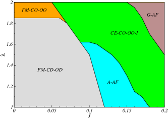
In order to represent the constituent LSMO and PCMO layers correctly in LSMO/PCMO (FM/AF) superlattices we first briefly outline the ground state phase diagram of the bulk system at electron density (half-doping) by varying the antiferromagnetic superexchange and Jahn-Teller coupling strength in Fig. 1. This bulk phase diagram is prepared using system size. To best of our knowledge, there has not been any study of the ground state phase diagram at in 3D systems. For smaller values of and , the system remains in a double exchange dominated ferromagnetic state to optimize the kinetic energy gain. Electron density of this ferromagnetic system remains homogeneous due to the orbital disordering (OD) and charge disordering (CD). As a result the system is metallic with finite density of state at the Fermi level () Pradhan . As we increase the value, keeping the superexchange small, the magnetic state remains in ferromagnetic, but it transits to a charge and orbital ordered insulating state (CO-OO-I) for . On the other hand, as superexchange is increased (keeping the small) the system transits to an A-type antiferromagnetic (A-AF) state (with structure factor peak at = . We obtained a CE-type antiferromagnetic, charge order (CO), orbital order (OO) phase (with simultaneous peaks at = , and by further increasing of the value. We also obtain CE-CO-OO phase for intermediate value of and large value of . This CE-CO-OO phase is strongly insulating due to the opening of gap at the Fermi level Pradhan ; Aliaga ; Popovic . For large values of and the phase changes to G-type AF (with structure factor ) which is shown in the top right hand corner of the phase diagram. Our phase diagram is consistent with previous 2D results Pradhan2 ; Yunoki1 .
III Parameter sets to represent LSMO and PCMO materials
To investigate the properties of LSMO/PCMO SLs we need to construct periodic arrangement of LSMO (ferromagnetic) and PCMO (antiferromagnetic) layers. We assign same electron density () to both the layers in our study. First we determine two sets of parameters that we will assign to LSMO-like and PCMO-like materials to mimic the essential physics of the individual constituent layers. From the phase diagram (see Fig. 1) it is clear that one can choose multiple parameter sets to simulate a ferromagnetic metal (LSMO-like). Such a dilemma also exist for replicating an antiferromagnetic insulating (PCMO-like) material. To proceed we set for both LSMO and PCMO layers and vary to differentiate the two systems. For () the bulk system is in FM-M (CE type AF-I) state as shown in Fig. 1 at . In contrast, at off-half-doping case (say = 0.55-0.65) the long-range charge and orbital ordered CE phase is diluted for . But, the overall AF-I nature of the system remains intact with local charge/magnetic ordering. The ferromagnetic ordering for at low temperatures is unaltered for . So, we set = 0.1 and ( = 0.1 and ) to mimic LSMO-type (PCMO-type) layers in our calculations unless otherwise mentioned. Henceforth, we call them LSMO and PCMO in our analysis.
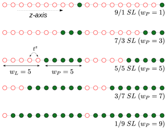
We construct various LSMO/PCMO (FM-M/AF-I) superlattices [schematically shown in Fig. 2] where LSMO layer of width and PCMO layer of width are periodically arranged. We employ periodic boundary conditions in our calculations. The width of the LSMO and PCMO layers are adjusted in such a way that the total thickness of the superlattice remains same along the out-of-plane direction. We mentioned earlier that our system size is and as a result total width of two LSMO layers and two PCMO layers is restricted to 20 planes. This construction is very similar to one of the reported experimental setup where total thickness of LSMO and PCMO layers is fixed but thickness of individual layers are varied Nakamura . These LSMO and PCMO layers are coupled at the interface via hopping parameters () and superexchange interactions () across the interface. In this setup our primary focus is to explore the induced magnetization in the antiferromagnetic PCMO layer with variation of (width of the AF layer) and its effect on the out-of-plane conductivity of the whole FM/AF superlattice systems. The strength of the long range Coulomb interaction is chosen to be throughout our calculations. All the calculations are performed in the presence of small applied magnetic field to align both FM layers in same direction.
We have calculated various physical observables to analyze the magnetotransport properties of the superlattices. The average magnetization of the system is determined by calculating where N is the total number of sites. The angular brackets represent the thermal average over the Monte Carlo generated equilibrium configurations. In addition, all the physical observables are averaged over ten different initial configurations of classical variables. We also calculate the magnetization of the individual planes by using the formula , where is the magnetization of the plane and represents number of sites in each plane. We also measure the local staggered magnetization of individual planes. In addition, the onset of charge ordering in antiferromagnetic PCMO layer is measured by calculating the staggered charge order . To probe the induced magnetization (local ferromagnetic ordering) in the antiferromagnetic PCMO layer we calculate the volume fraction of the FM nanoclusters [V(SO)] which is defined as, fraction of sites, say , for which for all the six nearest neighbor sites . We also calculate the density of states (DOS) at frequency by using the formula, where are the single particle eigen values.
To analyze the transport properties we calculate the conductivity of the FM/AF superlattices in the limit along the out-of-plane direction by using Kubo-Greenwood formalism Mahan ; Kumar1 ; Chakraborty :
where (a is the lattice parameter). represents the matrix elements of the paramagnetic current operator between the eigen states and with corresponding eigen energies and , respectively and . We extract conductivity by calculating the average conductivity for a small low-frequency interval defined as
where is chosen four to five times larger than the mean finite size gap of the system as estimated by the ratio of the bare bandwidth and the total number of eigen values.
IV Magnetotransport properties of the LSMO/PCMO superlattices at half-doping
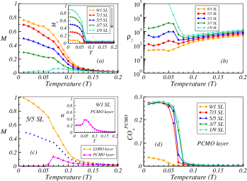
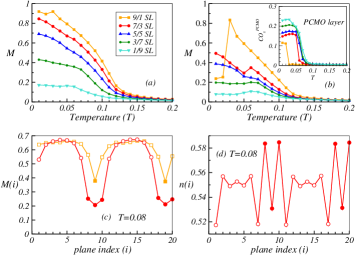
We first estimate the magnetization profile of different superlattices for case as shown in Fig. 3(a). The onset temperature of the ferromagnetic ordering of the SLs decreases with the increase of the PCMO layer width i.e. as we go from 9/1 SL to 1/9 SL as indicated by an arrow near the legend box in Fig. 3(a). The magnetization value of the superlattice system decreases with the increase of the PCMO layer width at low temperatures. In fact, the magnetization cease to exist for 1/9 SL at low temperatures. The staggered magnetization averaged over individual planes of the system is plotted in the inset of Fig. 3(a), shows that the ground state is dominated by the antiferromagnetic correlations for 1/9 SL. Now, we calculate the out-of-plane resistivity () for all five superlattices as shown in Fig. 3(b) to analyze the correspondence between magnetic and transport properties. Interestingly, 9/1 SL remains more or less metallic at very low temperatures due to the dominant ferromagnetic nature of the SL system. A metal-insulator transition (MIT) sets up in an intermediate temperature () for 7/3 and 5/5 SLs. The increases with increase of the PCMO layer width . So, the PCMO layer dominates the transport properties of the SL at larger and as a result 1/9 SL system is strongly insulating at low temperatures. The combined result of magnetization and resistivity of SL systems show that the 1/9 SL behaves as an AF-I system whereas the 9/1 SL behaves as a FM-M system similar to the bulk LSMO. Overall, the SL system transforms from a FM-M to AF-I phase with increase of the PCMO layer width . Our calculated magnetotransport results of LSMO/PCMO superlattices at are in good agreement with experimental results Nakamura ; Wadati .
To further understand the analogy between the observed magnetizations and the metal-insulator transitions in Figs. 3(a) and (b), particularly at intermediate values, we present the average magnetization of the individual LSMO and PCMO layers in Fig. 3(c) for 5/5 SL. The total magnetization is replotted in same figure. It is clear that the PCMO layer magnetization starts to decrease below the temperature and vanishes at very low temperatures. This decrease in PCMO layer magnetization is associated with the formation of charge ordering in the PCMO layer at that temperature. We plot the staggered charge ordered vs temperature of PCMO layers for 5/5 SL in Fig. 3(d). The onset of charge ordering at negates the induced ferromagnetic moments in PCMO layer below . In fact, the slope of the magnetization curve [see Fig. 3 (a)] of total 5/5 SL changes at which matches well with the charge ordering temperature. This temperature also coincides with the metal-insulator transition presented in Fig. 3(b). All these coherent results confirm that the main contribution to the magnetization of 5/5 SL comes only from the LSMO layer at low temperatures. The charge ordering of PCMO layers at low temperatures is also apparent for 7/3, 3/7 and 1/9 SLs [see Fig. 3(d)] that prohibits the magnetization in PCMO layer. The diminishing magnetization of PCMO layers decreases the magnetization of the overall superlattice system with the increase of PCMO layer width as shown in Fig. 3(a). But the charge ordering temperature and strength of charge ordering at low temperatures in PCMO layer remains comparatively small for = 1. As a result the induced magnetization in antiferromagnetic PCMO layer survives at low temperatures for 9/1 SL as shown in inset of Fig. 3(c).
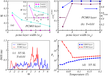
Next, we plot the induced magnetization in the antiferromagnetic PCMO layer of the superlattice systems for different width of the PCMO layer at two different temperatures [i.e. at low () and high () temperatures] in Fig. 4(a) to compare our results elaborately. Temperature is below the ferromagnetic of the LSMO layer but is larger than the charge ordering temperature of PCMO layers presented in Fig. 3(d). The induced magnetization in PCMO layers is finite for both and for = 1. At high temperatures (), above the onset of the charge ordering in PCMO layer, the induced magnetization persists up to larger . At very high value of the magnetization in PCMO layer will approach the bulk limit. Does the induced magnetization profile changes drastically if we increase the bandwidth of the material? To answer this we show the induced magnetization in PCMO layer using = 1.65 (smaller corresponds to larger bandwidth or vice versa Pradhan3 ) in the inset of Fig. 4(a). Our qualitative results remain almost unchanged.
Now we turn back to case. The induced magnetization in PCMO layer suddenly decreases with the increase of PCMO layer width at , unlike at where magnetization decreases rather slowly. There is a one-to-one correspondence between the induced magnetization and the charge ordering strength at in PCMO layers as shown in Fig. 4(b). As we mentioned above the strong charge ordered states for all SLs except 9/1 SL prohibits the induced magnetization in PCMO layers. The staggered magnetization in PCMO layers [see Fig. 4(b)] also follows the same trend to that of at low temperatures. These results emphasize that the PCMO layers (except for = 1) in LSMO/PCMO SLs are in charge ordered antiferromagnetic state at low temperatures. To reveal the insulating nature of the PCMO layers we plot the layer resolved density of states (DOS) of the 5/5 SL [see Fig. 4(c)] at for both LSMO and PCMO layers. The Fermi level is set at = 0. The DOS is finite at Fermi level for the LSMO layers whereas DOS is gapped at Fermi level for the PCMO layer. This indicate that LSMO (PCMO) layers are in metallic (insulating) state. The transverse resistivity of each layer with temperature (shown in Fig. 4(d)) further corroborates this scenario.
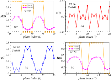
Next, we plot the plane-wise magnetization [M(i)] profile for 5/5 SL at in Fig. 5(a). The magnetization is saturated for each LSMO plane whereas the induced magnetization is negligible in all PCMO planes. This is obvious as magnetization in PCMO layer is negligibly small as we discussed in Fig. 3(c). It is apparently clear from our analysis that the induced magnetization in PCMO layer persists in a small temperature window which is above the charge ordering temperature in PCMO layer and below the FM of LSMO layer except for = 1. Does each plane of PCMO layers gets magnetized equally in this temperature window? To answer this we have plotted plane-wise magnetization [M(i)] vs plane index () of 5/5 SL at in Fig. 5(a). All the PCMO planes have finite magnetization which justify the magnetization of PCMO layer vs temperature curve shown in Fig. 3(c). Magnetization in interfacial planes is comparatively larger than the inner planes in PCMO layers at this temperature regime. On the other hand, the magnetization decreases as we move from inner planes to interfacial planes in LSMO layer. This is due to the average electron density variation as a result of charge transfer across the interfacial planes from LSMO to PCMO, which is evident from the plane-wise electron density profile [ vs ] plotted in Fig. 5(b). It also shows that the charge transfer occurs mainly at the interfacial planes whereas the electron density of inner planes of both LSMO and PCMO layers remains very close to the initial electron density, i.e. = 0.5. Furthermore, the associated LRC potential profile, shown in Fig. 5(c), is almost symmetric and a potential gradient across the interface is observed. This confirms that the amount of charge transfer occurs across the interface is very much controlled due to LRC potentials. Hence, the decrease of electron density from the interfacial LSMO layer, due to the charge transfer, leads to the decrease of the magnetization value at the interfacial LSMO layers, although minimal, as compared to the inner planes of LSMO layer [see Fig. 5(a)].
In addition, plane-wise magnetization profile of the 7/3 SL at two different temperatures ( = 0.01 and 0.08) are also shown in Fig. 5(d). They exhibit very similar characteristics as in 5/5 SL. These magnetization profiles at low temperature [see Figs. 5(a) and (d)] reveal that the magnetization of LSMO layer is saturated but the PCMO layer has negligible magnetization and as a result the SL system displays inhomogeneous phase-separated-like state. On the other hand the LSMO and PCMO layers of the SLs have finite magnetization at high temperatures () and the systems behave relatively homogeneous. The homogeneous (inhomogeneous) phase of the superlattices at high (low) temperatures matches well with the reported experimental results performed on this type of manganite superlattices Nakamura ; Wadati . Overall, it seems quite strenuous to destabilize the CO state (or in other terms, induce magnetization) in the PCMO layer at = 0.5 by varying the interfacial mechanisms through variation of PCMO layer thickness at low temperatures, mainly due to the robustness of the CO. Thus, the next step is analyze LSMO/PCMO superlattices at off-half-doping.
V Magnetotransport properties of the superlattices at off-half-doping
As we mentioned earlier, the AF phase at off-half-doping is not a perfect charge and orbital ordered (CO-OO) phase; the CO-OO is inherently somewhat diluted. Now the question arises: is it possible to destabilize the CO-OO state further in the off-half doped PCMO by tuning its layer thickness () in LSMO/PCMO superlattices? To answer this question, we study the similar kind of SLs with off-half doped PCMO, especially at = 0.55. In order to interpret the systematics of induced magnetic moments in PCMO layers and its effect on transport properties we analyze LSMO/PCMO superlattices at for various width of PCMO layers. We plot the magnetization vs temperature in Fig. 6(a) at . The onset temperature of the ferromagnetic ordering of SLs decreases with the increase of PCMO layer width , similar to case. The low temperature magnetization value of the SLs also decreases with . The small peak at observed for 9/1 SL is due to the sudden decrease in the magnetization of the PCMO layer as shown in Fig. 6(b). This fall in PCMO layer magnetization at is due the commencement of charge ordering [see the inset of Fig. 6(b)] in the PCMO layer. The magnetization of the PCMO layer in 7/3 SL also decreases at because of the onset of charge ordering in PCMO layer, but the magnetization increases again below . In fact, the charge ordering is observed for all SLs (charge ordering temperature increases with width of PCMO layer) but the abrupt change in the magnetization of the embedded PCMO layer near the charge ordering temperature is more prominent for thinner PCMO layers only. The induced magnetization in the thinner PCMO layers are relatively large at the time of the onset of charge ordering and as a result the drop is more prominent. Also, the induced magnetization sustains the impact of charge ordering for larger values of .
Next, to reveal the induced moment across the planes, we plot the plane-wise magnetization of 9/1 and 7/3 SLs at (just above the charge ordering temperature of PCMO layers in 7/3 SL) in Fig. 6(c). For visual impact we have shifted the result of 9/1 SL by one plane which is allowed due to the imposed periodic boundary conditions in our SL system. The induced magnetization in each PCMO plane is apparent from this plot. It is also clear that the magnetization of the interfacial LSMO planes are relatively smaller than the inner LSMO planes similar to case. The plane-wise electron density profiles plotted for 7/3 SL in Fig. 6(d) shows that the charge transfer occurs across the interfaces, from LSMO to PCMO and as a result the interfacial magnetizations in LSMO layer decreases.
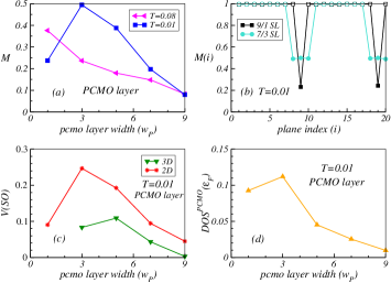
We plot the average induced magnetization in PCMO layer at in Fig. 7(a). This induced magnetization in PCMO layer decreases monotonically with the increase of PCMO layer width, similar to the results we obtained at high temperatures for case. Please note that is higher than the charge ordering temperatures of the embedded PCMO layers in our SLs. At low temperatures charge ordering is observed in the PCMO layers for all our SLs. But the strength of the charge ordering in PCMO layer increases with [as shown in inset of Fig. 6(b)]. It is important to note that the strength of the charge ordering in PCMO layer for case is comparatively weaker to that of case. The weakened charge ordering at intermediate values give rise to the coexistence of induced magnetization and charge ordering in the PCMO layer at low temperatures [Figs. 6(a) and (b)] which was not observed in case.
The induced magnetization in the PCMO layers at low temperature for SL for SL, in contrary to SLs, remains finite for all values studied in this work [see Fig. 7(a)]. Interestingly the induced magnetization in PCMO layers shows nonmonotonic behavior with . The optimum magnetization occurs for i.e., for 7/3 SL. The plane-wise magnetization profiles are shown for (9/1 SL) and (7/3 SL) in Fig. 7(b) at . Here also, we have shifted the result of 9/1 SL by one plane [as in Fig. 6(c)]. The plane-wise magnetization profile shows that the induced magnetization in individual PCMO planes are smaller in 9/1 SL as compared to that of 7/3 SL. To further probe the induced magnetism in PCMO layer we calculate the volume fraction of the ferromagnetic clusters [V(SO)] inside the PCMO layers. The low temperature 3D volume fraction shows that the fraction of ferromagnetic clusters decreases considerably for large [Fig. 7(c)] and as a result the magnetization of PCMO layer will approach the bulk PCMO limit at very large . But, at intermediate values of , we observed that a considerable amount of ferromagnetic clusters are present in PCMO layers. Unfortunately V(SO) of PCMO layer can not be calculated for . To include the ferromagnetic volume fraction of we evaluate the 2D volume fraction (calculated for each plane and averaged over the number of planes) of the PCMO layers. The low temperature 2D volume fraction shows nonmonotonic behavior with similar to the induced magnetization profile shown in Fig. 7(a). The induced magnetization in PCMO layers will most probably affect on the transport properties of the SLs. Hence in our next step we calculate the density of states at the Fermi level of the PCMO layers to ascertain the behavior of transport properties more closely at low temperatures () for different SLs as shown in Fig. 7(d). for different values also exhibit a nonmonotonic behaviors similar to the induced magnetization profile. All these coherent results indicate that the conductivity will also follow a nonmonotonic path with variation of PCMO layer width.
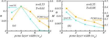
In fact, the out-of-plane conductivity (see Fig. 8(a)) of the superlattices follows a similar nonmonotonic characteristics at with optimum conductivity at . This shows that induced magnetization in the PCMO layers indeed smoothen the conducting paths between the ferromagnetic LSMO channels by reducing the scattering processes during the electrical conduction. As a result, the conductivity follows the induced magnetization profile of the embedded PCMO layers in the SL structures. On the other hand, the conductivity decreases monotonically with at high temperatures which is analogous to the induced magnetization profile in the embedded PCMO layers [see Fig. 8(b)]. Overall, our calculations establish a one-to-one correspondence between the magnetic and transport properties in the LSMO/PCMO superlattices. The nonmonotonic characteristics of the magnetotransport properties with variation of matches with the reported experimental results Nieb1 ; Nieb2 .
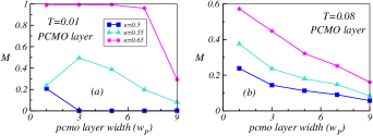
Finally, we want to show that the induction of magnetization is more easier as we go even further away from half-doping. For this, we calculate the induced magnetization profile in the PCMO layers for different SLs using at low () and high () temperatures. The induced magnetization profile in the PCMO layers of the superlattices for three different densities and are shown in Fig. 9(a) and 9(b) at low () and high () temperatures, respectively for comparison. For case the induced magnetization in the PCMO layers remains saturated up to and then start to recede (see Fig. 9(a)). This indicates that the entire superlattice convert to a ferromagnet for . So, it is easier to magnetize weakened charge ordered antiferromagnetic layer at . In the contrary, although induced magnetization for case is comparatively large to that of and cases, it decreases monotonically starting from at high temperatures as shown in Fig. 9(b).
Overall, our result at does not show any nonmonotonicity with variation of . If one wants to compare our results one-to-one with experiments at Nieb1 then we agree that nonmonotonicity of the magnetization in the antiferromagnetic layer at low temperatures is not reproduced exactly in our calculations. This may be due to the disorder effect in thinner PCMO layers that we have neglected in our calculations. Thin PCMO layers and interfacial planes (of both LSMO and PCMO layers) are likely to be more vulnerable to disorder due to strain effects and as a result the magnetization in thin PCMO likely to decrease in presence of disorder Pradhan . At the same time it is noteworthy to recover the nonmonotonic nature of the induced magnetization in PCMO layer at without taking any disorder effect into account.
VI Conclusions
In this paper, we have studied the magnetotransport properties of manganite based LSMO/PCMO like FM/AF superlattice systems using two-orbital double exchange model by incorporating superexchange interaction and Jahn-Teller lattice distortions. We focus on the induced ferromagnetism in PCMO layer at half-doping ( = 0.5) and off-half-doping ( = 0.55) cases that give rise to intriguing phase coexistence in FM/AF SL systems. The induced ferromagnetic moments in the antiferromagnetic PCMO layer decreases monotonically with increasing the antiferromagnetic layer width at high temperatures (just above the charge ordering temperature of PCMO layers but, below the ferromagnetic of LSMO) for both half-doping and off-half-doping scenarios. As we decrease the temperature the induced ferromagnetic moments in PCMO layer disappears or decreases considerably for half-doping. This is due to the onset of charge ordering in antiferromagnetic PCMO layers. Our calculations shows that the metal-insulator transition temperature of the LSMO/PCMO superlattices increases with increase of the PCMO layer width , similar to the experiments. We outline the underlying one-to-one correspondence between magnetic and transport properties. However, contrasting features appear at off-half-doping regime ( = 0.55). Our calculations comprehensively show that it is easier to induce ferromagnetic moment in weakened charge ordered state at = 0.55 even at low temperatures. Interestingly, the induced magnetization in PCMO layer and the conductivity of the total superlattice system shows nonmonotonic behavior with increase of in agreement with experiments.
ACKNOWLEDGEMENTS
We acknowledge use of the Meghnad2019 computer cluster at SINP.
References
- (1) Z. Huang, A. Ariando, R. X. Wang, A. Rusydi, J. Chen, H. Yang, T. Venkatesan, Adv. Mater. 30, 1802439 (2018).
- (2) J. Ngai, F. Walker, C. Ahn, Correlated oxide physics and electronics, Annu. Rev. Mater. Res. 44, 1 (2014).
- (3) F. Hellman, A. Hoffmann, Y. Tserkovnyak, G. S. Beach, E. E. Fullerton, C. Leighton, A. H. MacDonald, D. C. Ralph, D. A. Arena, H. A. Dürr, P. Fischer, J. Grollier, J. P. Heremans, T. Jungwirth, A. V. Kimel, B. Koopmans, I. N. Krivorotov, S. J. May, A. K. Petford-Long, J. M. Rondinelli, N. Samarth, I. K. Schuller, A. N. Slavin, M. D. Stiles, O. Tchernyshyov, A. Thiaville, B. L. Zink, Rev. Mod. Phys. 89, 025006 (2017).
- (4) B. Chen, H. Xu, C. Ma, S. Mattauch, D. Lan, F. Jin, Z. Guo, S. Wan, P. Chen, G. Gao, F. Chen, Y. Su, W. Wu, Science 357, 191 (2017).
- (5) H. Y. Hwang, Y. Iwasa, M. Kawasaki, B. Keimer, N. Nagaosa, and Y. Tokura, Nat. Mater. 11, 103 (2012).
- (6) A. Ohtomo, H. Y. A. Hwang, Nature 427, 423 (2004).
- (7) K. S. Takahashi, M. Kawasaki, Y. Tokura, Appl. Phys. Lett. 79, 1324 (2001).
- (8) J. Zheng, W. Shi, Zhe Li, J. Zhang, C. Y. Yang, Z. Zhu, M. Wang, J. Zhang, F. Han, H. Zhang, Y. Chen, F. Hu, B. Shen, Y. Chen, and J. Sun, ACS Nano 18, 9232 (2024).
- (9) J. Garcia-Barriocanal, J. C. Cezar, F. Y. Bruno, P. Thakur, N. B. Brookes, C. Utfeld, A. Rivera-Calzada, S. R. Giblin, J. W. Taylor, J. A. Duffy, S. B. Dugdale, T. Nakamura, K. Kodama, C. Leon, S. Okamoto, and J. Santamaria, Nat. Commun. 82, 1 (2010).
- (10) A. Ohtomo, D. A. Muller, J. L. Grazul, and H. Y. Hwang, Nature (London) 419, 378 (2002).
- (11) M. Gibert, M. Viret, A. Torres-Pardo, C. Piamonteze, P. Zubko, N. Jaouen, J. -M. Tonnerre, A. Mougin, J. Fowlie, S. Catalano, A. Gloter, O. Stephan, and J.-M. Triscone, Nano Lett. 15, 7355 (2015).
- (12) J. Hoffman, I. C. Tung, B. B. Nelson-Cheeseman, M. Liu, J. W. Freeland, and A. Bhattacharya, Phys. Rev. B 88, 144411 (2013).
- (13) L. F. Kourkoutis, J. H. Song, H. Y. Hwang, and D. A. Mullera, Proc. Natl. Acad. Sci. U.S.A. 107, 11682 (2010).
- (14) A. Ohtomo, D. A. Muller, J. L. Grazul, H. Hwang, Nature 419, 378(2002).
- (15) S. S. A. Seo, W. S. Choi, H. N. Lee, L. Yu, K. W. Kim, C. Bernhard, T. W. Noh, Phys. Rev. Lett. 99, 266801 (2007).
- (16) S. Okamoto, A. Millis, Nature 428, 630 (2004).
- (17) F. Y. Bruno, J. Garcia-Barriocanal, M. Varela, N. M. Nemes, P. Thakur, J. C. Cezar, N. B. Brookes, A. Rivera-Calzada, M. Garcia-Hernandez, C. Leon, S. Okamoto, S. J. Pennycook, and J. Santamaria, Phys. Rev. Lett. 106, 147205 (2011).
- (18) T. Koida, M. Lippmaa, T. Fukumura, K. Itaka, Y. Matsumoto, M. Kawasaki, and H. Koinuma, Phys. Rev. B 66, 144418 (2002).
- (19) A. Brinkman, M. Huijben, M. van Zalk, J. Huijben, U. Zeitler, J. C. Maan, W. G. van der Wiel, G. Rijnders, D. H. A. Blank, and H. Hilgenkamp, Nat. Mater. 6, 493 (2007).
- (20) N. Reyren, S. Thiel, A. D. Caviglia, L. Fitting-Kourkoutis, G. Hammerl, C. Richter, C. W. Schneider, T. Kopp, A. S. Ruetschi, D. Jaccard, M. Gabay, D. A. Muller, J. M. Triscone, and J. Mannhart, Science 317, 1196 (2007).
- (21) A. Gozar, G. Logvenov, L. Fitting Kourkoutis, A. T. Bollinger, L. A. Giannuzzi, D. A. Muller, I. Bozovic, Nature 455, 782 (2008).
- (22) D. A. Dikin, M. Mehta, C. W. Bark, C. M. Folkman, C. B. Eom, and V. Chandrasekhar, Phys. Rev. Lett. 107, 056802 (2011).
- (23) P. Yu, J. -S. Lee, S. Okamoto, M. D. Rossell, M. Huijben, C. -H. Yang, Q. He, J. -X. Zhang, S. Y. Yang, M. J. Lee, Q. M. Ramasse, R. Erni, Y. -H. Chu, D. A. Arena, C. -C. Kao, L. W. Martin, and R. Ramesh, Phys. Rev. Lett. 105, 027201 (2010).
- (24) M. Gibert, P. Zubko, R. Scherwitzl, J. Íñiguez, J. -M. Triscone, Nat. Mater. 11, 195 (2012).
- (25) G. Zhou, C. Song, Y. Bai, Z. Quan, F. Jiang, W. Liu, Y. Xu, S. S. Dhesi, and X. Xu, ACS Appl. Mater. Interfaces 9, 3156 (2017).
- (26) P. Zubko, S. Gariglio, M. Gabay, P. Ghosez, J. M. Triscone, Annu. Rev. Condens. Matter Phys. 2, 141 (2011).
- (27) X. Liang, H. Chen, and N. X. Sun, APL Mater. 9, 041114 (2021).
- (28) K. Bhoi, H. S. Mohanty, Ravikant, Md. F. Abdullah, D. K. Pradhan, S. N. Babu, A. K. Singh, P. N. Vishwakarma, A. Kumar, R. Thomas, and D. K. Pradhan, Scientific Reports 11, 3149 (2021).
- (29) R. Gupta and R. K. Kotnala, J. Mater. Sci. 57, 12710 (2022).
- (30) G. Lawes and G. Srinivasan, J. Phys. D: Appl. Phys. 44, 243001 (2011).
- (31) J. Mannhart, and D. G. Schlom, Science 327, 1607 (2010).
- (32) S. Brivio, M. Cantoni, D. Petti, and R. Bertacco, J. Appl. Phys. 108, 113906 (2010).
- (33) T. Yajima, Y. Hikita, and H. Y. Hwang, Nature Mater. 10, 198 (2011).
- (34) J. Shen, J. Cong, D. Shang, Y. Chai, S. Shen, K. Zhai, Y. Sun, Sci. Rep. 6, 34473 (2016).
- (35) R. Ramesh, N. A. Spaldin, Nat. Mater. 6, 21 (2007).
- (36) I. Zutic, J. Fabian, and S. D. Sarma, Rev. Mod. Phys. 76, 323 (2004).
- (37) E. Y. Tsymbal, O. N. Mryasov, and P. R. LeClair, J. Phys.: Condens. Matter 15, R109 (2003).
- (38) J. M. De Teresa, A. Barthelemy, A. Fert, J. P. Contour, F. Montaigne, and P. Seneor, Science 286, 507 (1999).
- (39) M. Ziese, Rep. Prog. Phys. 65, 143 (2002).
- (40) M. Bibes and A. Barthélémy, IEEE Trans. Electron Devices 54, 1003 (2007).
- (41) E. Dagotto, T. Hotta and A. Moreo, Phys. Rep. 344, 1 (2001).
- (42) I. Panagiotopoulos, C. Christides, M. Pissas, and D. Niarchos, Phys. Rev. B 60, 485 (1999).
- (43) I. N. Krivorotov, K. R. Nikolaev, A. Yu. Dobin, A. M. Goldman, and E. D. Dahlberg, Phys. Rev. Lett. 86, 5779 (2001).
- (44) M. Julliere, Phys. Lett. 54A, 225 (1975).
- (45) J. Salafranca, M. J. Calderon, and L. Brey, Phys. Rev. B 77, 014441 (2008).
- (46) J. Z. Sun, W. J. Gallagher, P. R. Duncombe, L. Krusin-Elbaum, R. A. Altman, A. Gupta, Y. Lu, G. Q. Gong, and G. Xiao, Appl. Phys. Lett. 69, 3266 (1996).
- (47) M.-H. Jo, N. D. Mathur, N. K. Todd, and M. G. Blamire, Phys. Rev. B 61, R14905 (2000).
- (48) M. Bibes, J. E. Villegas, and A. Barthelemy, Adv. Phys. 60, 5 (2011).
- (49) Y. Tokura, Rep. Prog. Phys. 69, 797 (2006).
- (50) Colossal Magnetoresistive Oxides, edited by Y. Tokura (Gordon and Breach, New York, 2000).
- (51) E. Dagotto, New J. Phys. 7, 67 (2005).
- (52) R. Kajimoto, H. Yoshizawa, Y. Tomioka, and Y. Tokura, Phys. Rev. B 66, 180402(R) (2002).
- (53) E. Dagotto, Nanoscale Phase Separation and Colossal Magnetoresistance (Springer-Verlag, Berlin, 2002).
- (54) Colossal Magnetoresistive Oxides, edited by T. Chatterji (Kluwer, Dordrecht, 2004).
- (55) S. Jin, T. H. Tiefel, M. McCormack, R. A. Fastnacht, R. Ramesh, L. H. Chen, Science 264, 413 (1994).
- (56) G. C. Xiong, Q. Li, H. L. Ju, S. M. Bhagat, S. E. Lofland, R. L. Greene, and T. Venkatesan, Appl. Phys. Lett. 67, 3031 (1995).
- (57) M. Uehara, S. Mori, C. H. Chen and S. -W. Cheong, Nature 399, 560 (1999).
- (58) M. Fath, S. Freisem, A. A. Menovsky, Y. Tomioka, J. Aarts, J. A. Mydosh, Science 285, 1540 (1999).
- (59) K. Pradhan and S. Yunoki, Phys. Rev. B 96, 214416 (2017).
- (60) A. Moreo, S. Yunoki, and E. Dagotto, Science 283, 2034 (1999).
- (61) D. Khomskii, Physica B 280, 325 (2000).
- (62) Ch. Simon, S. Mercone, N. Guiblin, C. Martin, A. Brulet, and G. Andre, Phys. Rev. Lett. 89, 207202 (2002).
- (63) R. von Helmolt, J. Wecker, B. Holzapfel, L. Schultz, and K. Samwer, Phys. Rev. Lett. 71, 2331 (1993).
- (64) Y. Tomioka, A. Asamitsu, Y. Moritomo, H. Kuwahara, and Y. Tokura, Phys. Rev. Lett. 74, 5108 (1995).
- (65) H. Kuwahara, Y. Tomioka, A. Asamitsu, Y. Moritomo, and Y. Tokura, Science 270, 961 (1995).
- (66) D. Niebieskikwiat, L. E. Hueso, J. A. Borchers, N. D. Mathur, and M. B. Salamon, Phys. Rev. Lett. 99, 247207 (2007).
- (67) D. Niebieskikwiat, L. E. Hueso, N. D. Mathur, and M. B. Salamon, Appl. Phys. Lett. 93, 123120 (2008).
- (68) A. Bhattacharya, S. J. May, S. G. E. te Velthuis, M. Warusawithana, X. Zhai, B. Jiang, J. M. Zuo, M. R. Fitzsimmons, S. D. Bader, and J. N. Eckstein, Phys. Rev. Lett. 100, 257203 (2008).
- (69) C. Adamo, X. Ke, P. Schiffer, A. Soukiassian, M. Warusawithana, L. Maritato, and D. G. Schlom, Appl. Phys. Lett. 92, 112508 (2008).
- (70) Z. Zhong and P. Hansmann, Phys. Rev. X 7, 011023 (2017).
- (71) S. J. May, P. J. Ryan, J. L. Robertson, J. -W. Kim, T. S. Santos, E. Karapetrova, J. L. Zarestky, X. Zhai, S. G. E. te Velthuis, J. N. Eckstein, S. D. Bader, and A. Bhattacharya, Nat. Mater. 8, 892 (2009).
- (72) S. Mukhopadhyay and I. Das, Eur. Phys. Lett. 83, 27003 (2008).
- (73) H. Li, J. R. Sun, and H. K. Wong, Appl. Phys. Lett. 80, 628 (2002).
- (74) D. Saurel, A. Brulet, A. Heinemann, C. Martin, S. Mercone, and C. Simon, Phys. Rev. B 73, 094438 (2006).
- (75) S. Mercone, V. Hardy, C. Martin, C. Simon, D. Saurel, and A. Brulet, Phys. Rev. B 68, 094422 (2003).
- (76) R. Cheng, K. Li, S. Wang, Z. Chen, C. Xiong, X. Xu, and Y. Zhang, Appl. Phys. Lett. 72, 2475 (1998).
- (77) S. Parkin, X. Jiang, C. Kaiser, A. Panchula, K. Roche, M. Samant, Proceedings of the IEEE 91(5), 661-680 (2003).
- (78) A. Urushibara, Y. Moritomo, T. Arima, A. Asamitsu, G. Kido, Y. Tokura, Phys. Rev. B 51, 14103 (1995).
- (79) Y. Tomoioka, A. Asamitsu, H. Kuwahara, Y. Moritomo, Y. Tokura, Phys. Rev.B 53, R1689 (1996).
- (80) M. Nakamura, D. Okuyama, J. S. Lee, T. Arima, Y. Wakabayashi, R. Kumai, M. Kawasaki, and Y. Tokura, Adv. Mater. 22, 500 (2010).
- (81) H. Wadati, J. Okamoto, M. Garganourakis, V. Scagnoli, U. Staub, E. Sakai, H. Kumigashira, T. Sugiyama, E. Ikenaga, M. Nakamura, M. Kawasaki, and Y. Tokura, New J. Phys. 16, 073044 (2014).
- (82) S. Dong, R. Yu, S. Yunoki, J. M. Liu, and E. Dagotto, Phys. Rev. B 78, 064414 (2008).
- (83) E. Dagotto, S. Yunoki, A. L. Malvezzi, A. Moreo, J. Hu, S. Capponi, D. Poilblanc, and N. Furukawa, Phys. Rev. B 58, 6414 (1998).
- (84) A. C. M. Green, Phys. Rev. B 63, 205110 (2001).
- (85) Z. Popovic and S. Satpathy, Phys. Rev. Lett. 88, 197201 (2002).
- (86) Y. Okimoto, T. Katsufuji, T. Ishikawa, A. Urushibara, T. Arima, and Y. Tokura, Phys. Rev. Lett. 75, 109 (1995).
- (87) S. Okamoto and A. J. Millis, Phys. Rev. B 70, 075101 (2004).
- (88) S. Yunoki, A. Moreo, E. Dagotto, S. Okamoto, S. S. Kancharla, and A. Fujimori, Phys. Rev. B 76, 064532 (2007).
- (89) K. Pradhan and A. P. Kampf, Phys. Rev. B 88, 115136 (2013).
- (90) C. Lin and A. J. Millis, Phys. Rev. B 78, 184405 (2008).
- (91) B. R. K. Nanda and S. Satpathy, Phys. Rev. B 78, 054427 (2008).
- (92) R. Yu, S. Yunoki, S. Dong, and E. Dagotto, Phys. Rev. B 80, 125115 (2009).
- (93) S. Kumar, P. Majumdar, Eur. Phys. J. B 50, 571 (2006).
- (94) S. Halder, Subrat K. Das, and K. Pradhan, Phys. Rev. B 108, 235111 (2023).
- (95) K. Pradhan and A. P. Kampf, Phys. Rev. B 87, 155152 (2013).
- (96) H. Aliaga, D. Magnoux, A. Moreo, D. Poilblanc, S. Yunoki, and E. Dagotto, Phys. Rev. B 68, 104405 (2003).
- (97) K. Pradhan, A. Mukherjee, and P. Majumdar, Phys. Rev. Lett. 99, 147206 (2007).
- (98) S. Yunoki, T. Hotta, and E. Dagotto, Phys. Rev. Lett. 84, 3714 (2000).
- (99) G. D. Mahan, Quantum Many Particle Physics (Plenum, New York, 1990).
- (100) S. Kumar and P. Majumdar, Eur. phys. Lett. 65, 75 (2004).
- (101) S. Chakraborty, S. Halder, and K. Pradhan, Phys. Rev. B 108, 165110 (2023).