UAV-Enabled Wireless Networks with Movable-Antenna Array:
Flexible Beamforming and Trajectory Design
Abstract
Recently, movable antenna (MA) array becomes a promising technology for improving the communication quality in wireless communication systems. In this letter, an unmanned aerial vehicle (UAV) enabled multi-user multi-input-single-output system enhanced by the MA array is investigated. To enhance the throughput capacity, we aim to maximize the achievable data rate by jointly optimizing the transmit beamforming, the UAV trajectory, and the positions of the MA array antennas. The formulated data rate maximization problem is a highly coupled non-convex problem, for which an alternating optimization based algorithm is proposed to get a sub-optimal solution. Numerical results have demonstrated the performance gain of the proposed method compared with conventional method with fixed-position antenna array.
Index Terms:
Movable-antenna array, unmanned aerial vehicles, transmit beamforming, trajectory design.I Introduction
Recently, unmanned aerial vehicle (UAV)-enabled communications have emerged as a key technology to ensure long-term communications and flexible placements in the next generation cellular networks. [1]. The relative high working altitude of the UAVs can provide stronger line-of-sight links between the UAVs and the ground users compared with conventional ground base station, which improves the channel gain with better data rates for the intensive demand of users [2]. However, the antenna beam gain is still a bottleneck to improve the throughout capacity in UAV-enabled communications. To address this issue, movable antenna (MA) technology is proposed to overcome the antenna beam gain limitation in wireless communications [3]. Specifically, spatial variation can be further utilized by MA, i.e., the positions of the antennas at the transmitter or/and the receiver can be dynamically adjusted in their certain regions to enable better quality of communication links, thus the higher throughput capacity can be obtained[4].
The effectiveness, robustness, and adaptability of the MA array have been verified in previous works [5, 6, 7, 8, 9]. Specifically, compressed sensing based channel estimation for wireless communications enhanced with MA array is investigated in [5]. The simultaneously enhancing and/or nulling the signal power at desired and/or undesired directions with MA array is studied in [6]. In [7], the achievable secrecy rate is optimized in the MA array-enabled secure communication system with joint optimization of transmit beamforming and the positions of all movable antennas. The transmit covariance matrix and the position of each MAs are jointly designed for a multiple-input multiple-output (MIMO) system in [8]. Moreover, the total transmit power of users is optimized in an MA-enhanced multiple-access channel system studied in [9]. On the other hand, the UAV-assisted communications have shown to improve the communication efficiency [10, 11, 12, 13]. The time allocation and UAV trajectory are joint optimized to minimize the system energy consumption [10]. The minimum data rate of Internet of thing (IoT) users is maximized in an IoT system studied in [11], where multiple UAVs are dispatched to power the IoT users, and then to collect data transmitted by the IoT users. To better represent the data rate and timeliness, a task-aware UAV trajectory is designed in [12], where the age of information is minimized among all ground users. In [13], the non-orthogonal multiple access enabled UAV systems is investigated, where the energy efficiency is maximized among all users to improve spectrum efficiency and large-scale connectivity. However, in previous works [5, 6, 7, 8, 9], the MA arrays are only deployed at fixed entity, lacking of flexibility. Moreover, these UAV-enabled systems [10, 11, 12, 13] only consider a single antenna or a fixed antenna array. Therefore, they are short of the utilization of antenna spatial variation, resulting in throughput bottleneck.
To solve these problems, we aim to fully utilize the spatial variation along with beamforming design via the MA array according to the positions of the UAV and users in a multi-user (MU) multi-input-single-output (MISO) system. The total achievable data rate of all users is maximized by jointly optimizing the transmit beamforming, the positions of all MAs, and the flying trajectory of the UAV. An efficient alternating optimization based algorithm is developed to solve the non-convex problem. Simulation results demonstrate the performance gain of proposed scheme compared to the conventional fixed-position antenna array scheme.
II System model and Problem Formulation
We consider an UAV communication system, where a single UAV serves single-antenna users. The set of users is denoted as . The UAV provides data transmission service for users when the flies from the initial position to the final position within a time period seconds. The time period is divided into slots, each with duration . Since the flying routine of the UAV is continuous, we discretize the flying by a certain position in each time slot, where the two-dimensional (2D) location of the UAV at time slot is given by , with fixed altitude . Hence, the velocity of the UAV is , which is limited by the minimum speed and the maximum speed . Besides, the acceleration of the UAV is also bounded by the maximum acceleration . The location of the -th user is denoted as .
The UAV is equipped with a linear MA array with size . The set of the MA array is denoted as , where the position of the -th MA at time slot is given by . Hence, the positions of the MA array can be written as . As a result, the steering vector of the MA array can be expressed as
| (1) |
where is the steering angle towards the -th user and is the wavelength. We use to represent for simplicity. Let denote the transmit beamforming vector of the UAV for communicating with the -th user at time slot . We assume the UAV-to-ground links are line of sight (LoS) channels, and the free-space path loss from the UAV to the -th user is given by , where is a constant value at a reference distance . To this end, the received signal-to-interference-plus-noise ratio (SINR) of the -th user at time slot can be derived as
| (2) |
where denotes the noise power at the -th user. The achievable data rate of the UAV for communicating with the -th user at time slot can be given by
| (3) |
In this work, we aim to maximize the total achievable data rate of users, by jointly optimizing the the positions of the MA array , the transmit beamforming at the UAV, and the UAV trajectory . Therefore, the problem is formulated as
| (4a) | ||||
| (4b) | ||||
| (4c) | ||||
| (4d) | ||||
| (4e) | ||||
where (4a) denotes the transmit power limitation, (4b) is the range of positions of all antennas, (4c) represents that the distance between adjacent MAs cannot lower than the minimum distance for preventing the coupling effect, (4d) and (4e) are the UAV kinematic constraints. (P1) is non-convex due to the high coupling among the optimization variables, which is hard to solve by conventional methods. Conversely, alternating optimization (AO) is an efficient and robustness method to solve such problems, by iteratively solving part of the variables while fixing others. The AO-based algorithm for solving (P1) is presented in the following section.
III Alternating Optimization for (P1)
III-A Optimizing Given and
Let , then we have , and . By substituting with , problem (P1) can be rewritten as
| (5a) | ||||
| (5b) | ||||
where is given by
| (6) |
and .
The problem (P2) is still non-convex regarding the non-concave nature of the objective, and the rank constraint (5b). Hence, we approximate the objective function by the successive convex approximation (SCA), where the -th iteration of the local point of is . The objective under -th iteration can be given by
| (7) |
where and are given by
| (8) |
| (9) |
Hence, the problem (P2) can be approximated as problem (P2.) in the -th iteration, which is given by
In problem (P2.), the objective function w.r.t. is concave. However, the constraint (5b) is still non-convex. To address this, we relax the rank constraints to convert problem (P2.) into a standard convex optimization problem (RP2.). Although the relaxed solution may not ensure rank-one matrices, Gaussian randomization can approximate a rank-one solution if required. Fortunately, by leveraging similar analyses from the prior work [14], we find that that an optimal rank-one solution always exists. Hence, Gaussian randomization is unnecessary for solving problem (P2.). Due to space limitations, the detailed proof is omitted.
III-B Optimizing Given and
As indicated by Eq. (1), exhibits complexity and non-linearity w.r.t , which makes the UAV trajectory optimization become very difficult. To address this issue, we utilize the -th iteration of the UAV trajectory to approximate the variables in related to the the -th iteration of the UAV trajectory. Thus, is rewritten as
| (11) |
where .
Thus, the objective function of (P1) can be reformulated as
| (12) |
where , , and . Obviously, the first term of is non-concave w.r.t. , but it is convex w.r.t. . By applying the SCA method, the lower-bound for the first term of can be expressed as
| (13) |
Besides, the second term of (12) is non-convex w.r.t. . By introducing a slack variable , this term is approximated by , where satisfies
| (14) |
Moreover, according to the SCA method, (4d) can be transformed into a convex constraint as and
| (15) |
III-C Optimizing Given and
As indicated by Eq. (3), the achievable data rate is a monotonically increasing function of SINR . Therefore, the objective function of problem (P1) can be transformed into , which is a nonlinear fractional problem and can be handled by the Dinkelbach method. By introducing a parameter to denote the SINR, the objective function of (P1) is transformed into
| (17) |
which is a non-convex function. Motivated by [15], we relax it by using the SCA method. For ease of exposition, we define . Furthermore, we represent the -th element of as , where denotes its amplitude and denotes its phase. Then, can be further expressed as
| (18) |
where . We use Taylor expansion to deal with the . Specifically, for a given , the second-order Taylor expansion of is
| (19) |
Then, for given in the -th iteration, by letting and , we can obtain
| (20) |
where , , and are expressed as
| (21) |
| (22) |
| (23) | ||||
with and . By introducing a slack variable , we can obtain a standard quadratic constraint, i.e.,
| (24) |
Moreover, given that has a structure similar to , we can transform it by modifying the procedure utilized to construct the relaxed quadratic constraint (24). Specifically, we have
| (25) |
| (26) |
where , , , and are expressed as
| (27) |
| (28) |
| (29) |
with . By introducing a slack variable , we can obtain a standard quadratic constraint, i.e.,
| (30) |
which can be solved efficiently by convex optimization solvers. Hence, the objective function (17) can be converted to
| (31) |
Then, the problem (P1) can be approximated as problem (P4.) in the -th iteration, which is given by
| (4b), (4c), (24), and (30), | ||||
where and . Problem (P4.) is reformulated as a standard convex problem w.r.t to , and can be solved by CVX toolbox.
III-D Alternating Optimization
The AO-based algorithm for solving (P1) is depicted in Algorithm 1. Given that the total achievable data rate is non-decreasing over iterations and has an upper bound, Algorithm 1 is ensured to converge. In addition, the aforementioned three sub-problems are solved by interior point method through CVX. The complexity of the three sub-problems is , , and , respectively. As a result, the overall complexity of solving (P1) is .
IV Numerical Results
In this section, we provide numerical results to validate the performance of our proposed scheme. In the simulation, we consider an area of with users. Similar to [7, 14], we set the minimum distance between adjacent MAs as , the range of positions of all antennas as , the maximum transmit power as , the noise power at each receiver as , the constant value , the range of UAV’s horizontal flight speed as , the flight altitude as , and the time period .
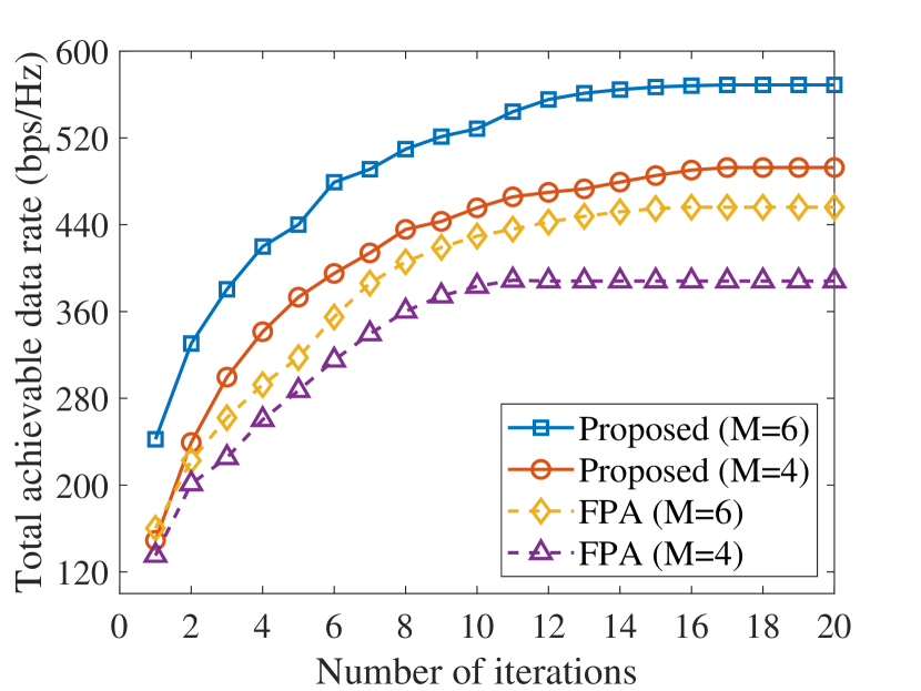
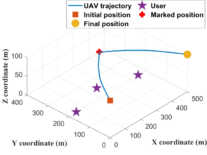
The convergence of the proposed MA array-based scheme and the fixed-position antenna array (FPA) scheme (only the beamforming and the trajectory are optimized) is illustrated in Fig. 2. The proposed AO-based algorithm is observed to be efficient where all schemes can converge within iterations. The proposed scheme with achieves the highest total achievable data rate due to the fully optimized beamforming gain with more antennas. An example of optimized UAV trajectory is demonstrated in Fig. 2. We can observe that the UAV flies to the suitable positions between users to achieve better performance. Note that we analyse the beamforming gain in Fig. 6 and Fig. 6 at the marked position (the red marked in Fig. 2).
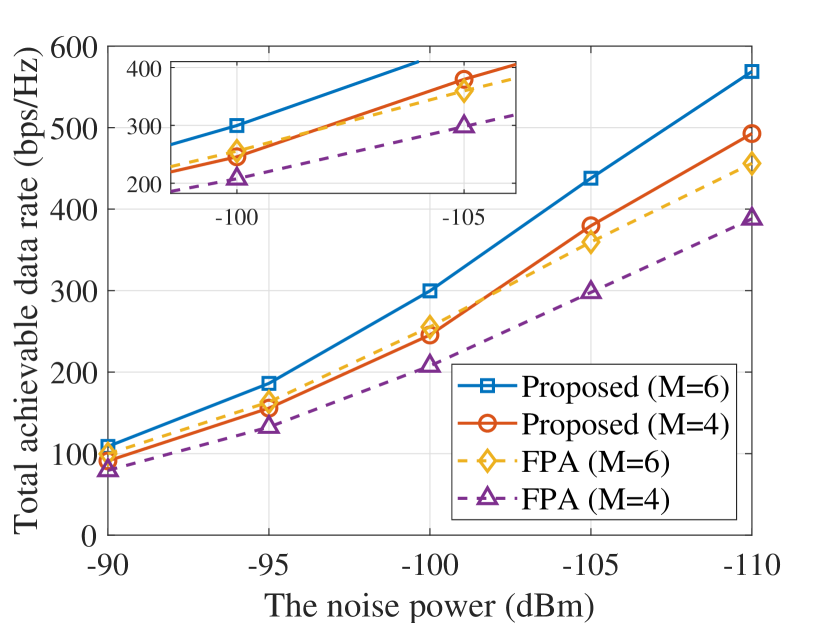
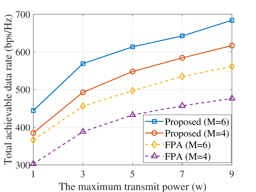
In Fig. 4, the total achievable data rate versus the noise power is presented. As we can observe, the proposed scheme with fewer antennas (the yellow curve where ) even achieves higher performance compared to the FPA scheme with a larger number of antennas (the red curve where ) under low noise power (), which verifies the performance gain benefited from the optimization of antenna positions via MA array. As shown in Fig. 4, the total achievable data rate versus the maximum transmit power is illustrated. From Fig. 4, the performance gap between the proposed scheme and the FPA scheme with same number of antennas increases with the maximum transmit power, which demonstrates the effectiveness of beamforming gain from the optimization of antenna positions via MA array.
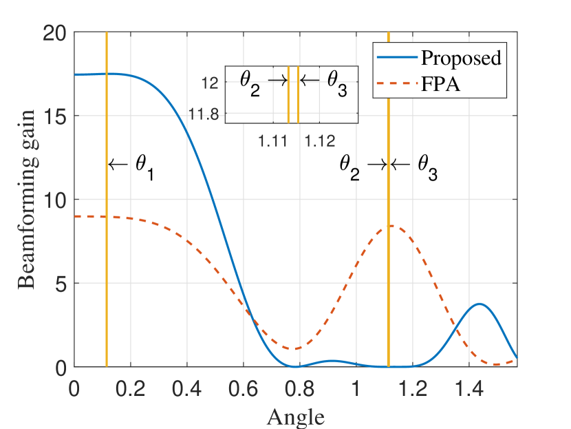
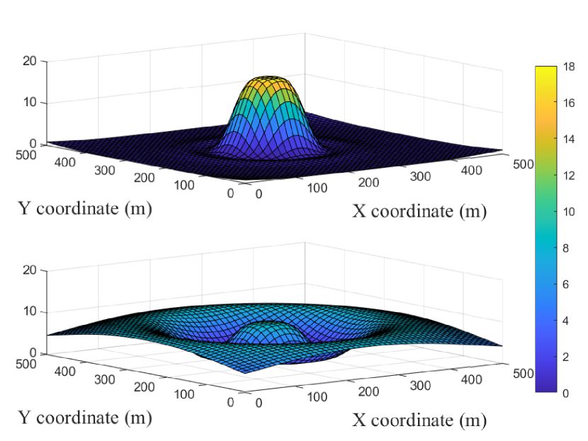
Fig. 6 and Fig. 6 show the beamforming gain of the proposed scheme and the FPA scheme at the angle , where . The UAV is flying at the marked position denoted in Fig. 2. We can observe that the FPA scheme only achieves around % beamforming gain at the angle () towards the central user compared with the proposed MA scheme, while consumes the residual power at the other angle (), resulting in lower data rate. On the other hand, the proposed MA scheme is capable of adjusting the antenna position dynamically according to the positions of the UAV and the users. Therefore, higher performance is guaranteed.
V Conclusion
This letter explores the total achievable data rate maximization problem in a novel UAV-enabled MU-MISO systems enhanced by MA array. The transmit beamforming, the UAV trajectory, and the antenna positions of MA array are jointly optimized by an AO-based algorithm. Numerical results verify the effective performance gain obtained by MA array, compared with fixed-position antenna array scenario.
References
- [1] Y. Zeng, Q. Wu, and R. Zhang, “Accessing from the sky: A tutorial on UAV communications for 5G and beyond,” Proc. IEEE, vol. 107, no. 12, Dec. 2019.
- [2] Q. Wu, J. Xu, Y. Zeng, D. W. K. Ng, N. Al-Dhahir, R. Schober, and A. L. Swindlehurst, “A comprehensive overview on 5G-and-beyond networks with UAVs: From communications to sensing and intelligence,” IEEE J. Sel. Areas Commun., vol. 39, no. 10, pp. 2912–2945, Oct. 2021.
- [3] L. Zhu, W. Ma, and R. Zhang, “Movable antennas for wireless communication: Opportunities and challenges,” IEEE Commun. Mag., pp. 1–7, to appear in 2024.
- [4] J. Zheng, J. Zhang, H. Du, D. Niyato, S. Sun, B. Ai, and K. B. Letaief, “Flexible-position MIMO for wireless communications: Fundamentals, challenges, and future directions,” IEEE Wireless Commun., pp. 1–9, to appear in 2024.
- [5] W. Ma, L. Zhu, and R. Zhang, “Compressed sensing based channel estimation for movable antenna communications,” IEEE Commun. Lett., vol. 27, no. 10, pp. 2747–2751, Oct. 2023.
- [6] L. Zhu, W. Ma, and R. Zhang, “Movable-antenna array enhanced beamforming: Achieving full array gain with null steering,” IEEE Commun. Lett., vol. 27, no. 12, pp. 3340–3344, Dec. 2023.
- [7] G. Hu, Q. Wu, K. Xu, J. Si, and N. Al-Dhahir, “Secure wireless communication via movable-antenna array,” IEEE Signal Process. Lett., vol. 31, pp. 516–520, Feb. 2024.
- [8] W. Ma, L. Zhu, and R. Zhang, “Mimo capacity characterization for movable antenna systems,” IEEE Trans. Wireless Commun., vol. 23, no. 4, pp. 3392–3407, Apr. 2024.
- [9] L. Zhu, W. Ma, B. Ning, and R. Zhang, “Movable-antenna enhanced multiuser communication via antenna position optimization,” IEEE Trans. Wireless Commun., pp. 1–1, to appear in 2024.
- [10] Y. Zeng, J. Xu, and R. Zhang, “Energy minimization for wireless communication with rotary-wing UAV,” IEEE Trans. Wireless Commun., vol. 18, no. 4, pp. 2329–2345, Apr. 2019.
- [11] W. Luo, Y. Shen, B. Yang, S. Wang, and X. Guan, “Joint 3-D trajectory and resource optimization in multi-UAV-enabled IoT networks with wireless power transfer,” IEEE Internet Things J., vol. 8, no. 10, pp. 7833–7848, May 2021.
- [12] G. Chen, C. Cheng, X. Xu, and Y. Zeng, “Minimizing the age of information for data collection by cellular-connected UAV,” IEEE Trans. Veh. Technol., vol. 72, no. 7, pp. 9631–9635, Jul. 2023.
- [13] Z. Liu, J. Qi, Y. Shen, K. Ma, and X. Guan, “Maximizing energy efficiency in UAV-assisted NOMA–MEC networks,” IEEE Internet Things J., vol. 10, no. 24, pp. 22 208–22 222, Dec. 2023.
- [14] Z. Lyu, G. Zhu, and J. Xu, “Joint maneuver and beamforming design for uav-enabled integrated sensing and communication,” IEEE Trans. Wireless Commun., vol. 22, no. 4, pp. 2424–2440, Apr. 2023.
- [15] W. Ma, L. Zhu, and R. Zhang, “Multi-beam forming with movable-antenna array,” IEEE Commun. Lett., vol. 28, no. 3, pp. 697–701, Mar. 2024.