Layered Chirp Spread Spectrum Modulations for LPWANs

Ali Waqar Azim, Ahmad Bazzi, Roberto Bomfin, Raed Shubair, Marwa Chafii Ali Waqar Azim is with Department of Telecommunication Engineering, University of Engineering and Technology, Taxila, Pakistan (email: aliwaqarazim@gmail.com).Ahmad Bazzi, Roberto Bomfin and Raed Shubair and Marwa Chafii are with the Engineering Division, New York University (NYU) Abu Dhabi, 129188, UAE (email: ahmad.bazzi,raed.shubair, marwa.chafii@nyu.edu). Marwa Chafii is also with NYU WIRELESS, NYU Tandon School of Engineering, Brooklyn, 11201, NY, USA .
Abstract

This article examines two chirp spread spectrum techniques specifically devised for low-power wide-area networks (LPWANs) to optimize energy and spectral efficiency (SE). These methods referred to as layered CSS (LCSS) and layered dual-mode CSS (LDMCSS), involves utilizing multiple layers for multiplexing symbols with varying chirp rates. These waveform designs exemplify a high degree of SE compared to existing schemes. Additionally, LDMCSS necessitates a lesser number of layers than LCSS to attain comparable SE, thereby reducing computational complexity. These proposed techniques can employ coherent and non-coherent detection and can be adjusted to achieve various spectral efficiencies by altering the number of multiplexed layers. Unlike our proposed LCSS and LDMCSS, other CSS alternatives for LPWANs cannot provide the same level of flexibility and SE. The performance of these techniques is evaluated in terms of bit error rate under different channel conditions, as well as with phase and frequency offsets.

Index Terms:
LoRa, chirp spread spectrum, IoT.

I Introduction

Low-power wide-area networks (LPWANs) are crucial for Internet-of-Things (IoT), as they enable communication between battery-powered devices while consuming minimal power. One such LPWAN technology is Long Range (LoRa)-WAN, which uses a proprietary waveform, LoRa as a physical layer modulation. LoRa is a simple form of chirp spread spectrum (CSS) and can balance sensitivity and data rates for fixed channel bandwidths by using different spreading factors (SF) as described in [1, 2]. Semtech corporation, which holds the LoRa patent, has never published the details of the modulation’s signal structure design. However, Vangelista in [3], M. Chiani, and A. Elzanaty in [4] have explained the waveform design, spectral properties, detection principles, etc. LoRa symbols are defined using M𝑀M cyclic time shifts of the chirp, which are used as the information-bearing elements. These cyclic time shifts correspond to frequency shifts (FSs) of the complex conjugate of the chirp signal, i.e., down-chirp signal; thus, LoRa can be considered FS chirp modulation. The scalable parameter that allows for different spectral efficiencies and energy efficiencies for LoRa is the SF, i.e., Ξ»=log2⁑(M)πœ†subscript2𝑀\lambda=\log_{2}(M), where Ξ»=⟦7,12βŸ§πœ†712\lambda=\llbracket 7,12\rrbracket. Ξ»πœ†\lambda is equivalent to the number of bits a LoRa symbol can transmit in a symbol duration of Tssubscript𝑇sT_{\mathrm{s}}.

LoRa is widely adopted but has a relatively low achievable spectral efficiency (SE) across the bands it operates in. As a result, alternatives that are more spectrally efficient such as CSS schemes like [5, 6, 7, 8, 9, 10, 11, 12, 13, 14, 15, 16, 17, 18, 19] have been explored. The waveform design of these CSS variants has been studied in-depth in [20], which include some schemes that use FSs in both the in-phase and quadrature components, like [6, 10, 13]. In contrast, others employ phase shifts (PSs) like in [7, 15]. Some also use the index modulation, for example, [12, 13]. While these variants generally have better spectral efficiencies than LoRa, they also have limitations.

The most spectral-efficient schemes among those listed are the in-phase and quadrature time-domain multiplexed (IQ-TDM)-CSS [17] and the dual-mode (DM)-TDM-CSS [19]. IQ-TDM-CSS offers four times higher SE relative to the classical LoRa while being more energy-efficient than it. However, due to the use of both the in-phase and the quadrature domains, non-coherent detection is not possible. Moreover, IQ-TDM-CSS is also very sensitive to phase and frequency offsets making it less practical. In contrast, DM-TDM-CSS rectifies the limitation of IQ-TDM-CSS by permitting forthright non-coherent, coherent detection processes while being resilient to the phase and frequency offsets. Nonetheless, for both approaches, the alphabet cardinality, M𝑀M is the only tunable parameter to attain different spectral or energy efficiencies. To be more precise, IQ-TDM-CSS and DM-TDM-CSS can transmit 4​λ4πœ†4\lambda and 4β€‹Ξ»βˆ’44πœ†44\lambda-4 bits per Tssubscript𝑇sT_{\mathrm{s}}. Thus, for Ξ»=⟦7,12βŸ§πœ†712\lambda=\llbracket 7,12\rrbracket, a limited number of points are available on the SE versus energy (EE) performance curve. This indicates the achievability of a limited number of spectral efficiencies, where the maximum achievable SE for IQ-TDM-CSS and DM-TDM-CSS is 4​λ/M4πœ†π‘€\nicefrac{{4\lambda}}{{M}} bits/s/Hz and 4β€‹Ξ»βˆ’4/M4πœ†4𝑀\nicefrac{{4\lambda-4}}{{M}} bits/s/Hz, respectively. Some approaches like slope-shift keying interleaved chirp spreading (SSK-ICS)-LoRa, DM-CSS, and discrete chirp rate keying (DCRK)-CSS are also more efficient than classical LoRa; however, their maximum achievable SE is considerably less than IQ-TDM-CSS and DM-TDM-CSS. Since this work aims to propose approaches capable of achieving high SE that are also adaptable in terms of achieving different spectral and energy efficiencies; therefore, we consider IQ-TDM-CSS and DM-TDM-CSS for comparison. We also consider TDM-CSS [17] for comparison because, like the proposed approaches, it also classifies as TDM modulation. The SE of TDM-CSS is 2​λ/M2πœ†π‘€\nicefrac{{2\lambda}}{{M}} bits/s/Hz, which is twice that of LoRa.

The article proposes layered CSS (LCSS) and layered DMCSS (LDMCSS), that enhance the performance of TDM-CSS and DM-TDM-CSS, respectively, by utilizing time-domain multiplexing to combine symbols with different chirp rates. LCSS multiplexes symbols with varying chirp rates from LoRa, while LDMCSS multiplexes symbols with varying chirp rates from a modified version of DM-CSS that does not incorporate the PSs. Unlike LDMCSS, which uses one even and one odd FS for the un-chirped symbol in each layer, LCSS employs only one activated FS per un-chirped symbol in each layer. This results in LDMCSS requiring half the number of layers compared to LCSS to achieve similar SE, reducing the transceiver complexity by half. The proposed waveform design combines the time-domain multiplexing design with the existing schemes to develop a layered signal structure. But at the same time, the proposed approaches demonstrate remarkable adaptability to obtain varying spectral and energy efficiency, allowing for customization according to specific application requirements. They differ from existing waveform designs due to their degree of flexibility. It is highlighted that the the layered CSS schemes offer an extra degree of freedom that LoRa does not have, which is beneficial when a more diverse set of SE is desired. Therefore, these schemes have a lot of potential as workable alternatives to established waveform designs for LPWANs.

In the subsequent sections of this article, we will comprehensively depict the waveform design of LCSS and LDMCSS schemes. Following the study of the transmission characteristics, we will furnish the coherent and non-coherent detection mechanisms. Furthermore, we will analyze the interference that arises due to the layered signal structure of the proposed schemes. The layered signal structure of the proposed schemes engenders inter-layer interference that can diminish the performance of the schemes. Additionally, we will analyze the orthogonality of the proposed schemes. We will also present simulation and numerical results to demonstrate the performance of the proposed schemes. The results demonstrate that the proposed schemes surpass the classical approaches while providing substantially higher SE and improved EE. Additionally, we will illustrate that the proposed schemes can be adjusted to provide various spectral and energy efficiencies by adding or removing layers in the signal structure at the cost of increased or reduced computational complexity.

Against the given background, the contributions of this work are as follows:

  1. 1.

    We propose LCSS and LDMCSS schemes as alternatives to state-of-the-art CSS schemes (including LoRa) for LPWANs. We demonstrate that the layered signal structures result in energy and spectral-efficient schemes, that are robust against frequency and phase offsets.

  2. 2.

    We thoroughly elucidate the transceiver architecture of LCSS and LDMCSS by providing a detailed description of the waveform generation process and the coherent and non-coherent detection mechanisms. This includes a clear explanation of the steps involved in the generation and detection processes and the design choices made for each scheme.

  3. 3.

    We analytically examine the interference that transpires due to the superposition of time-domain multiplexed symbols in LCSS and LDMCSS. The analysis indicates that interference increases with the number of layers. The orthogonality analysis, on the other hand, illustrates that the symbols lose their orthogonality due to the layered structure. These analysis proffers an understanding of the manner in which the interference impacts the quality of the signal and the efficacy of the detection mechanisms.

  4. 4.

    We provide theoretical BER expressions for the proposed LCSS and LDMCSS schemes.

  5. 5.

    The article conducts an assessment and comparison of the performance of the proposed LCSS and LDMCSS with benchmark schemes by utilizing a set of performance metrics, specifically: (i) SE versus required signal-to-noise ratio (SNR) per bit for a target bit error rate (BER) of 10βˆ’3superscript10310^{-3}; (ii) BER performance in an additive white Gaussian noise (AWGN) and a frequency-selective fading channel; and (iii) BER performance considering phase and frequency offsets.

The remainder of the article is organized as follows: In Section II presents a comprehensive elucidation of the system model and the transceiver architecture pertaining to the LCSS and LDMCSS. Section III conducts a scrutiny of the orthogonality of the schemes proposed. Subsequently, in Section IV, an examination of the interference arising from the layered signal configuration within the proposed schemes. The theoretical BER expressions for the proposed schemes are provided in Section V for non-coherent detection and upper-bound BER expressions are developed for coherent detection. The outcomes of simulated results are presented in Section VI, and finally, in Section VII, conclusions are drawn based upon the results gleaned in Section VI.

II Proposed Layered CSS Modulation Schemes

In this section, we first provide a system model. After that, we present the transmission and detection mechanisms of LCSS and LDMCSS. To design the transceiver architecture, our approach simply extends the well-known methodologies of the receiver design to the new transmission scheme in order to keep the complexity low, given that the maximum likelihood implementation of the layered CSS schemes would have considerably higher complexity.

II-A System Model

We consider a chirped CSS symbol is composed of two primary elements: (i) an un-chirped symbol, g​(n)𝑔𝑛g(n), where n=⟦0,Mβˆ’1βŸ§π‘›0𝑀1n=\llbracket 0,M-1\rrbracket; and (ii) a spreading symbol, c​(n)𝑐𝑛c(n) that spreads the information in the bandwidth, B=M/Ts𝐡𝑀subscript𝑇sB=\nicefrac{{M}}{{T_{\mathrm{s}}}}, where Tssubscript𝑇sT_{\mathrm{s}} is the symbol period. The un-chirped symbol can have one (as in LoRa), or multiple (as in DM-CSS) activated FSs. Spreading results in an injective mapping of FSs to cyclic time shifts. It is noteworthy that spreading on an un-chirped symbol can have different slope/chirp rates [9, 11]. Here, by different chirp rates, we mean the normalized chirp rate over the bandwidth. Specifically, LoRa chirp rate is defined as a=B/Tsπ‘Žπ΅subscript𝑇sa=\nicefrac{{B}}{{T_{\mathrm{s}}}} Hz/s, such that in Tssubscript𝑇sT_{\mathrm{s}} seconds the signal spans B𝐡B Hz. In our case, we generalize the chirp rate to be a=l​B/Tsπ‘Žπ‘™π΅subscript𝑇sa=\nicefrac{{lB}}{{T_{\mathrm{s}}}}. Notice that this does not imply that our signal spans l​B𝑙𝐡lB Hz in Tssubscript𝑇sT_{\mathrm{s}} seconds because the signal is wrapped around the limits [βˆ’B/2,B/2]𝐡2𝐡2\left[-\nicefrac{{B}}{{2}},\nicefrac{{B}}{{2}}\right]. Basically, we can increase the number of bits/s/Hz if we have multiple signals with different chirp rates in the same bandwidth, which is not possible in the typical single-user LoRa transmission.

In the discrete time, the CSS symbol consists of M𝑀M samples and is given as s​(n)=g​(n)​c​(n)𝑠𝑛𝑔𝑛𝑐𝑛s(n)=g(n)c(n). Then, the discrete-time baseband received symbol assuming perfect time and frequency synchronization for simplicity111The numerical evaluation of these schemes consider phase and frequency offsets. is given as:

y​(n)=h​s​(n)+w​(n),π‘¦π‘›β„Žπ‘ π‘›π‘€π‘›y(n)=hs(n)+w(n), (1)

where hβ„Žh is the complex channel gain, and w​(n)𝑀𝑛w(n) corresponds to AWGN samples. We are considering AWGN and its characterization in terms of its single-sided noise power spectral density, N0subscript𝑁0N_{0}, and noise variance, Οƒn2=N0​BsuperscriptsubscriptπœŽπ‘›2subscript𝑁0𝐡\sigma_{n}^{2}=N_{0}B. In LPWANs, CSS symbols maintain a narrow bandwidth of 500500500 kHz or smaller; therefore, a flat fading channel can have constant attenuation over the entire B𝐡B.

II-B Layered Chirp Spread Spectrum

Refer to caption
Figure 1: LCSS transmitter architecture.
Refer to caption
Figure 2: LCSS coherent receiver architecture.

II-B1 Transmission

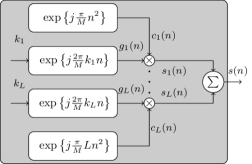
Fig. 1 shows the generalized transmitter architecture of LCSS. LCSS uses Mcsubscript𝑀cM_{\mathrm{c}} (positive) chirp rates, and the number of layers is L=Mc𝐿subscript𝑀cL=M_{\mathrm{c}} (which is assumed to be a multiple of two for simplicity). The un-chirped symbol of the l𝑙lth layer with one activated FS is gl​(n)=exp⁑{j​πM​2​kl​n}subscriptπ‘”π‘™π‘›π‘—πœ‹π‘€2subscriptπ‘˜π‘™π‘›g_{l}(n)=\exp\left\{j\frac{\pi}{M}2k_{l}n\right\}, where l=⟦1,LβŸ§π‘™1𝐿l=\llbracket 1,L\rrbracket, kl∈[0,Mβˆ’1]subscriptπ‘˜π‘™0𝑀1k_{l}\in\left[0,M-1\right] and n=⟦0,Mβˆ’1βŸ§π‘›0𝑀1n=\llbracket 0,M-1\rrbracket. Note that the klsubscriptπ‘˜π‘™k_{l} is attained after the binary-to-decimal conversion of Ξ»l=log2⁑(M)subscriptπœ†π‘™subscript2𝑀\lambda_{l}=\log_{2}(M) bits. The spreading symbol of the l𝑙lth layer, cl​(n)=exp⁑{j​πM​l​n2}subscriptπ‘π‘™π‘›π‘—πœ‹π‘€π‘™superscript𝑛2c_{l}(n)=\exp\left\{j\frac{\pi}{M}ln^{2}\right\} is then used to attain the l𝑙lth layer chirped symbol, i.e.,:

sl​(n)=gl​(n)​cl​(n)=exp⁑{j​πM​(2​kl​n+l​n2)}.subscript𝑠𝑙𝑛subscript𝑔𝑙𝑛subscriptπ‘π‘™π‘›π‘—πœ‹π‘€2subscriptπ‘˜π‘™π‘›π‘™superscript𝑛2s_{l}(n)=g_{l}(n)c_{l}(n)=\exp\left\{j\frac{\pi}{M}\left(2k_{l}n+ln^{2}\right)\right\}. (2)

Subsequently, the L𝐿L chirped symbols are added to attain a composite signal s​(n)𝑠𝑛s(n) as:

s​(n)=βˆ‘l=1Lsl​(n)=βˆ‘l=1Lexp⁑{j​πM​(2​kl​n+l​n2)}.𝑠𝑛superscriptsubscript𝑙1𝐿subscript𝑠𝑙𝑛superscriptsubscript𝑙1πΏπ‘—πœ‹π‘€2subscriptπ‘˜π‘™π‘›π‘™superscript𝑛2s(n)=\sum_{l=1}^{L}s_{l}(n)=\sum_{l=1}^{L}\exp\left\{j\frac{\pi}{M}\left(2k_{l}n+ln^{2}\right)\right\}. (3)

The symbol energy of s​(n)𝑠𝑛s(n) is equal to Es=𝔼​{|s​(n)|2}=βˆ‘n=0Mβˆ’1𝔼​{|s​(n)|2}subscript𝐸s𝔼superscript𝑠𝑛2superscriptsubscript𝑛0𝑀1𝔼superscript𝑠𝑛2E_{\mathrm{s}}=\mathbb{E}\{|s(n)|^{2}\}=\sum_{n=0}^{M-1}\mathbb{E}\{|s(n)|^{2}\}, and the number of bits it transmits is λ¯=βˆ‘l=1LΞ»l=Lβ€‹Ξ»Β―πœ†superscriptsubscript𝑙1𝐿subscriptπœ†π‘™πΏπœ†\overline{\lambda}=\sum_{l=1}^{L}\lambda_{l}=L\lambda. Here, 𝔼​{β‹…}𝔼⋅\mathbb{E}\{\cdot\} denotes the expectation operator.

II-B2 Detection

For clarity of exposition, we consider the following vectorial representations, π’š=[y​(0),y​(1),β‹―,y​(Mβˆ’1)]Tπ’šsuperscript𝑦0𝑦1⋯𝑦𝑀1T\boldsymbol{y}=\left[y(0),y(1),\cdots,y(M-1)\right]^{\mathrm{T}}, and 𝒔=[s​(0),s​(1),β‹―,s​(Mβˆ’1)]T𝒔superscript𝑠0𝑠1⋯𝑠𝑀1T\boldsymbol{s}=\left[s(0),s(1),\cdots,s(M-1)\right]^{\mathrm{T}}, where [β‹…]Tsuperscriptdelimited-[]β‹…T[\cdot]^{\mathrm{T}} is the transpose operator.

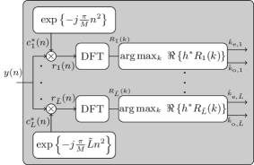
The coherent detector for LCSS is depicted in Fig. 2. Considering that channel state information (CSI), hβ„Žh is available at the receiver and the transmit symbols are equiprobable, the coherent detection dictates maximizing the probability of receiving π’šπ’š\boldsymbol{y} when 𝒔𝒔\boldsymbol{s} was sent given hβ„Žh, i.e., prob​(π’š|𝒔,h)probconditionalπ’šπ’”β„Ž\mathrm{prob}\left(\boldsymbol{y}|\boldsymbol{s},h\right). Then, the coherent detection problem given as:

{k^l}l=1L=arg​maxkl⁑prob​(π’š|𝒔,h)=arg​maxklβ‘β„œβ‘{βŸ¨π’š,hβ€‹π’”βŸ©}.superscriptsubscriptsubscript^π‘˜π‘™π‘™1𝐿argsubscriptsubscriptπ‘˜π‘™probconditionalπ’šπ’”β„Žargsubscriptsubscriptπ‘˜π‘™π’šβ„Žπ’”\begin{split}\left\{\hat{k}_{l}\right\}_{l=1}^{L}=\mathrm{arg}\max_{k_{l}}~{}\mathrm{prob}\left(\boldsymbol{y}|\boldsymbol{s},h\right)=\mathrm{arg}\max_{k_{l}}~{}\Re\left\{\langle\boldsymbol{y},h\boldsymbol{s}\rangle\right\}.\end{split} (4)

Considering that (β‹…)βˆ—superscriptβ‹…βˆ—(\cdot)^{\ast} evaluates the complex conjugate, βŸ¨π’š,hβ€‹π’”βŸ©π’šβ„Žπ’”\langle\boldsymbol{y},h\boldsymbol{s}\rangle is simplified as:

βŸ¨π’š,hβ€‹π’”βŸ©=hβˆ—β€‹βˆ‘n=0Mβˆ’1βˆ‘l=1Ly​(n)​slβˆ—β€‹(n)=hβˆ—β€‹βˆ‘n=0Mβˆ’1βˆ‘l=1Ly​(n)​glβˆ—β€‹(n)​clβˆ—β€‹(n)=hβˆ—β€‹βˆ‘n=0Mβˆ’1βˆ‘l=1Lrl​(n)​glβˆ—β€‹(n)=hβˆ—β€‹βˆ‘l=1LRl​(k),π’šβ„Žπ’”superscriptβ„Žβˆ—superscriptsubscript𝑛0𝑀1superscriptsubscript𝑙1𝐿𝑦𝑛superscriptsubscriptπ‘ π‘™βˆ—π‘›superscriptβ„Žβˆ—superscriptsubscript𝑛0𝑀1superscriptsubscript𝑙1𝐿𝑦𝑛superscriptsubscriptπ‘”π‘™βˆ—π‘›superscriptsubscriptπ‘π‘™βˆ—π‘›superscriptβ„Žβˆ—superscriptsubscript𝑛0𝑀1superscriptsubscript𝑙1𝐿subscriptπ‘Ÿπ‘™π‘›superscriptsubscriptπ‘”π‘™βˆ—π‘›superscriptβ„Žβˆ—superscriptsubscript𝑙1𝐿subscriptπ‘…π‘™π‘˜\begin{split}\langle\boldsymbol{y},h\boldsymbol{s}\rangle&={h}^{\ast}\sum_{n=0}^{M-1}\sum_{l=1}^{L}y(n){s}_{l}^{\ast}(n)={h}^{\ast}\sum_{n=0}^{M-1}\sum_{l=1}^{L}y(n)g_{l}^{\ast}(n)c_{l}^{\ast}(n)\\ &={h}^{\ast}\sum_{n=0}^{M-1}\sum_{l=1}^{L}r_{l}(n)g_{l}^{\ast}(n)={h}^{\ast}\sum_{l=1}^{L}R_{l}(k),\end{split} (5)

for k=⟦0,Mβˆ’1βŸ§π‘˜0𝑀1k=\llbracket 0,M-1\rrbracket, where rl​(n)=y​(n)​clβˆ—β€‹(n)subscriptπ‘Ÿπ‘™π‘›π‘¦π‘›superscriptsubscriptπ‘π‘™βˆ—π‘›r_{l}(n)=y(n)c_{l}^{\ast}(n). Rl​(k)subscriptπ‘…π‘™π‘˜R_{l}(k) is the discrete Fourier transform (DFT) of rl​(n)subscriptπ‘Ÿπ‘™π‘›r_{l}(n). The simplification of βŸ¨π’š,hβ€‹π’”βŸ©π’šβ„Žπ’”\langle\boldsymbol{y},h\boldsymbol{s}\rangle in (5), leads to:

{k^l}l=1L=arg​maxklβ‘β„œβ‘{hβˆ—β€‹βˆ‘l=1LRl​(k)}.superscriptsubscriptsubscript^π‘˜π‘™π‘™1𝐿argsubscriptsubscriptπ‘˜π‘™superscriptβ„Žβˆ—superscriptsubscript𝑙1𝐿subscriptπ‘…π‘™π‘˜\begin{split}\left\{\hat{k}_{l}\right\}_{l=1}^{L}=\mathrm{arg}\max_{k_{l}}~{}\Re\left\{{h}^{\ast}\sum_{l=1}^{L}R_{l}(k)\right\}.\end{split} (6)

The FSs can also be dis-jointly identified as:

k^l=arg​maxklβ‘β„œβ‘{hβˆ—β€‹Rl​(k)}.subscript^π‘˜π‘™argsubscriptsubscriptπ‘˜π‘™superscriptβ„Žβˆ—subscriptπ‘…π‘™π‘˜\begin{split}\hat{k}_{l}=\mathrm{arg}\max_{k_{l}}~{}\Re\left\{{h}^{\ast}R_{l}(k)\right\}.\end{split} (7)

For coherent detection, the DFT of the un-chirped symbol is first computed using the chirp rate respective to each layer, i.e., Rl​(k)subscriptπ‘…π‘™π‘˜R_{l}(k). Then, the FS of the same layer is identified by evaluating the maximum argument of β„œβ‘{Rl​(k)}subscriptπ‘…π‘™π‘˜\Re\{R_{l}(k)\} multiplied by the conjugate of hβ„Žh.

Refer to caption
Figure 3: LCSS non-coherent receiver architecture.

When CSI, hβ„Žh is unavailable, the non-coherent detection mechanism is generally employed. The computational complexity of the non-coherent detector is notably less than that of coherent detection, resulting in low-power consumption and low-cost LPWAN components. The non-coherent detector for LCSS is illustrated in Fig. 3. For non-coherent detection, the FSs of the l𝑙lth layer are identified dis-jointly as:

k^l=arg​maxkl⁑|Rl​(k)|.subscript^π‘˜π‘™argsubscriptsubscriptπ‘˜π‘™subscriptπ‘…π‘™π‘˜\begin{split}\hat{k}_{l}=\mathrm{arg}\max_{k_{l}}~{}\left|R_{l}(k)\right|.\end{split} (8)

Note that (8) follows (5) as the non-coherent detector evaluates the maximum argument of |βˆ‘n=0Mβˆ’1y​(n)​sβˆ—β€‹(n)|superscriptsubscript𝑛0𝑀1𝑦𝑛superscriptπ‘ βˆ—π‘›\left|\sum_{n=0}^{M-1}y(n){s}^{\ast}(n)\right|. The DFT of rl​(n)subscriptπ‘Ÿπ‘™π‘›r_{l}(n) is evaluated, which yields Rl​(k)subscriptπ‘…π‘™π‘˜R_{l}(k). Then, the FS of the l𝑙lth layer is identified by determining the maximum argument of |Rl​(k)|subscriptπ‘…π‘™π‘˜|R_{l}(k)| as in (8).

II-C Layered Dual-Mode Chirp Spread Spectrum

Refer to caption
Figure 4: LDMCSS transmitter architecture.

II-C1 Transmission

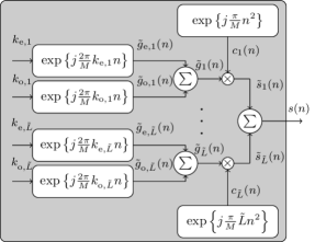
Unlike LCSS, where only one FS was activated, in LDMCSS, each layer activates two FSs, one even and one odd, as in the DM-CSS, thus halving the number of layers relative to LCSS to attain almost the same SE. Let L~~𝐿\tilde{L} be the number of layers for LDMCSS; then, we have L~=L/2~𝐿𝐿2\tilde{L}=\nicefrac{{L}}{{2}}. Fig. 4 illustrates the transmitter architecture of LDMCSS. For the un-chirped symbol at each layer, a total of M𝑀M FSs are available; half are even, and half are odd. For the l~~𝑙\tilde{l}th layer, where l~=⟦1,L~⟧~𝑙1~𝐿\tilde{l}=\llbracket 1,\tilde{L}\rrbracket, the even and the odd activated FSs, ke,l~subscriptπ‘˜e~𝑙k_{\mathrm{e},\tilde{l}} and ko,l~subscriptπ‘˜o~𝑙k_{\mathrm{o},\tilde{l}}, are attained after binary-to-decimal conversion of Ξ»~e,l~=log2⁑(M/2)subscript~πœ†e~𝑙subscript2𝑀2\tilde{\lambda}_{\mathrm{e},\tilde{l}}=\log_{2}(\nicefrac{{M}}{{2}}) and Ξ»~o,l~=log2⁑(M/2)subscript~πœ†o~𝑙subscript2𝑀2\tilde{\lambda}_{\mathrm{o},\tilde{l}}=\log_{2}(\nicefrac{{M}}{{2}}) bits, where ke,l~∈[0,M/2βˆ’1]subscriptπ‘˜e~𝑙0𝑀21k_{\mathrm{e},\tilde{l}}\in\left[0,\nicefrac{{M}}{{2}}-1\right] and ko,l~∈[0,M/2βˆ’1]subscriptπ‘˜o~𝑙0𝑀21k_{\mathrm{o},\tilde{l}}\in\left[0,\nicefrac{{M}}{{2}}-1\right]. Since the number of layers in LDMCSS are half relative to LCSS, the number of chirp rates needed is also half in LDMCSS compared to LCSS, i.e., M~c=Mc/2subscript~𝑀csubscript𝑀c2\tilde{M}_{\mathrm{c}}=\nicefrac{{M_{\mathrm{c}}}}{{2}}. The un-chirped symbol for the l~~𝑙\tilde{l}th layer in LDMCSS is g~l~​(n)=g~e,l~​(n)+g~o,l~​(n)=exp⁑{j​πM​2​ke,l~​n}+exp⁑{j​πM​2​ko,l~​n}subscript~𝑔~𝑙𝑛subscript~𝑔e~𝑙𝑛subscript~𝑔o~π‘™π‘›π‘—πœ‹π‘€2subscriptπ‘˜e~π‘™π‘›π‘—πœ‹π‘€2subscriptπ‘˜o~𝑙𝑛\tilde{g}_{\tilde{l}}(n)=\tilde{g}_{\mathrm{e},\tilde{l}}(n)+\tilde{g}_{\mathrm{o},\tilde{l}}(n)=\exp\left\{j\frac{\pi}{M}2k_{\mathrm{e},\tilde{l}}~{}n\right\}+\exp\left\{j\frac{\pi}{M}2k_{\mathrm{o},\tilde{l}}~{}n\right\}. Then using the spreading symbol for the l~​t​h~π‘™π‘‘β„Ž\tilde{l}th layer, cl~​(n)=exp⁑{j​πM​l~​n2}subscript𝑐~π‘™π‘›π‘—πœ‹π‘€~𝑙superscript𝑛2{c}_{\tilde{l}}(n)=\exp\left\{j\frac{\pi}{M}\tilde{l}~{}n^{2}\right\}, the chirped symbol for the l~~𝑙\tilde{l}th layer is as follows:

s~l​(n)=g~l~​(n)​cl~​(n)=exp⁑{j​πM​(2​ke,l~​n+l~​n2)}+exp⁑{j​πM​(2​ko,l~​n+l~​n2)}.subscript~𝑠𝑙𝑛subscript~𝑔~𝑙𝑛subscript𝑐~π‘™π‘›π‘—πœ‹π‘€2subscriptπ‘˜e~𝑙𝑛~𝑙superscript𝑛2π‘—πœ‹π‘€2subscriptπ‘˜o~𝑙𝑛~𝑙superscript𝑛2\begin{split}\tilde{s}_{l}(n)=\tilde{g}_{\tilde{l}}(n)c_{\tilde{l}}(n)&=\exp\left\{j\frac{\pi}{M}\left(2k_{\mathrm{e},\tilde{l}}~{}n+\tilde{l}n^{2}\right)\right\}\\ &~{}+\exp\left\{j\frac{\pi}{M}\left(2k_{\mathrm{o},\tilde{l}}~{}n+\tilde{l}n^{2}\right)\right\}.\end{split} (9)

The composite chirped symbol of L~~𝐿\tilde{L} layers is attained as:

s​(n)=βˆ‘l~=0L~s~l~​(n)=βˆ‘l~=0L~exp⁑{j​πM​(2​ke,l~​n+l~​n2)}+βˆ‘l~=0L~exp⁑{j​πM​(2​ko,l~​n+l~​n2)}.𝑠𝑛superscriptsubscript~𝑙0~𝐿subscript~𝑠~𝑙𝑛superscriptsubscript~𝑙0~πΏπ‘—πœ‹π‘€2subscriptπ‘˜e~𝑙𝑛~𝑙superscript𝑛2superscriptsubscript~𝑙0~πΏπ‘—πœ‹π‘€2subscriptπ‘˜o~𝑙𝑛~𝑙superscript𝑛2\begin{split}s(n)=\sum_{\tilde{l}=0}^{\tilde{L}}\tilde{s}_{\tilde{l}}(n)&=\sum_{\tilde{l}=0}^{\tilde{L}}\exp\left\{j\frac{\pi}{M}\left(2k_{\mathrm{e},\tilde{l}}~{}n+\tilde{l}n^{2}\right)\right\}\\ &~{}+\sum_{\tilde{l}=0}^{\tilde{L}}\exp\left\{j\frac{\pi}{M}\left(2k_{\mathrm{o},\tilde{l}}~{}n+\tilde{l}n^{2}\right)\right\}.\end{split} (10)

The symbol energy of the LDMCSS transmit symbol, s​(n)𝑠𝑛s(n) is Es=𝔼​{|s​(n)|2}=βˆ‘n=0Mβˆ’1𝔼​{|s​(n)|2}subscript𝐸s𝔼superscript𝑠𝑛2superscriptsubscript𝑛0𝑀1𝔼superscript𝑠𝑛2E_{\mathrm{s}}=\mathbb{E}\{|s(n)|^{2}\}=\sum_{n=0}^{M-1}\mathbb{E}\{|s(n)|^{2}\}, and the total number of bits transmitted per symbol is Ξ»~=βˆ‘l~=1L~(Ξ»~e,l~+Ξ»~o,l~)=L~​(2β€‹Ξ»βˆ’2)~πœ†superscriptsubscript~𝑙1~𝐿subscript~πœ†e~𝑙subscript~πœ†o~𝑙~𝐿2πœ†2\tilde{\lambda}=\sum_{\tilde{l}=1}^{\tilde{L}}\left(\tilde{\lambda}_{\mathrm{e},\tilde{l}}+\tilde{\lambda}_{\mathrm{o},\tilde{l}}\right)=\tilde{L}(2\lambda-2). Note that the number of bits transmitted per symbol in LDMCSS is marginally less than those in LCSS. For example, if we consider SF of Ξ»πœ†\lambda, then for L=4𝐿4L=4 and L~=2~𝐿2\tilde{L}=2, the number of bits transmitted per symbol in LCSS and LDMCSS is λ¯=4β€‹Ξ»Β―πœ†4πœ†\overline{\lambda}=4\lambda and Ξ»~=4β€‹Ξ»βˆ’4~πœ†4πœ†4\tilde{\lambda}=4\lambda-4, respectively.

II-C2 Detection

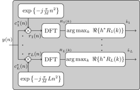
The coherent detector for LDMCSS is illustrated in Fig. 5. The coherent detection problem for LDMCSS is given as:

{k^e,l~,k^o,l~}l=1L=arg​maxke,ko⁑prob​(π’š|𝒔,h)=arg​maxke,koβ‘β„œβ‘{βŸ¨π’š,hβ€‹π’”βŸ©},superscriptsubscriptsubscript^π‘˜e~𝑙subscript^π‘˜o~𝑙𝑙1𝐿argsubscriptsubscriptπ‘˜esubscriptπ‘˜oprobconditionalπ’šπ’”β„Žargsubscriptsubscriptπ‘˜esubscriptπ‘˜oπ’šβ„Žπ’”\begin{split}\left\{\hat{k}_{\mathrm{e},\tilde{l}},\hat{k}_{\mathrm{o},\tilde{l}}\right\}_{l=1}^{L}&=\mathrm{arg}\max_{k_{\mathrm{e}},k_{\mathrm{o}}}~{}\mathrm{prob}\left(\boldsymbol{y}|\boldsymbol{s},h\right)=\mathrm{arg}\max_{k_{\mathrm{e}},k_{\mathrm{o}}}~{}\Re\left\{\langle\boldsymbol{y},h\boldsymbol{s}\rangle\right\},\end{split} (11)

where kesubscriptπ‘˜ek_{\mathrm{e}} and kosubscriptπ‘˜ok_{\mathrm{o}} are the even and the odd FSs. βŸ¨π’š,hβ€‹π’”βŸ©π’šβ„Žπ’”\langle\boldsymbol{y},h\boldsymbol{s}\rangle in (11) simplifies to:

βŸ¨π’š,hβ€‹π’”βŸ©=hβˆ—β€‹βˆ‘n=0Mβˆ’1βˆ‘l~=1L~y​(n)​s~l~βˆ—β€‹(n)=hβˆ—β€‹(βˆ‘n=0Mβˆ’1βˆ‘l~=1L~rl~​(n)​ge,l~βˆ—β€‹(n)+βˆ‘n=0Mβˆ’1βˆ‘l~=1L~rl~​(n)​go,l~βˆ—β€‹(n))=hβˆ—β€‹βˆ‘l~=1L~(Rl~​(ke)+Rl~​(ko)).π’šβ„Žπ’”superscriptβ„Žβˆ—superscriptsubscript𝑛0𝑀1superscriptsubscript~𝑙1~𝐿𝑦𝑛superscriptsubscript~𝑠~π‘™βˆ—π‘›superscriptβ„Žβˆ—superscriptsubscript𝑛0𝑀1superscriptsubscript~𝑙1~𝐿subscriptπ‘Ÿ~𝑙𝑛superscriptsubscript𝑔e~π‘™βˆ—π‘›superscriptsubscript𝑛0𝑀1superscriptsubscript~𝑙1~𝐿subscriptπ‘Ÿ~𝑙𝑛superscriptsubscript𝑔o~π‘™βˆ—π‘›superscriptβ„Žβˆ—superscriptsubscript~𝑙1~𝐿subscript𝑅~𝑙subscriptπ‘˜esubscript𝑅~𝑙subscriptπ‘˜o\begin{split}\langle\boldsymbol{y},h\boldsymbol{s}\rangle&={h}^{\ast}\sum_{n=0}^{M-1}\sum_{\tilde{l}=1}^{\tilde{L}}y(n)\tilde{s}_{\tilde{l}}^{\ast}(n)\\ &={h}^{\ast}\left(\sum_{n=0}^{M-1}\sum_{\tilde{l}=1}^{\tilde{L}}r_{\tilde{l}}(n)g_{\mathrm{e},\tilde{l}}^{\ast}(n)+\sum_{n=0}^{M-1}\sum_{\tilde{l}=1}^{\tilde{L}}r_{\tilde{l}}(n)g_{\mathrm{o},\tilde{l}}^{\ast}(n)\right)\\ &={h}^{\ast}\sum_{\tilde{l}=1}^{\tilde{L}}\biggl{(}R_{\tilde{l}}(k_{\mathrm{e}})+R_{\tilde{l}}(k_{\mathrm{o}})\biggr{)}.\end{split} (12)

Using (12), the coherent detection problem in (11) becomes:

{k^e,l~,k^o,l~}l=1L=arg​maxke,koβ‘β„œβ‘{hβˆ—β€‹βˆ‘l~=1L~(Rl~​(ke)+Rl~​(ko))}.superscriptsubscriptsubscript^π‘˜e~𝑙subscript^π‘˜o~𝑙𝑙1𝐿argsubscriptsubscriptπ‘˜esubscriptπ‘˜osuperscriptβ„Žβˆ—superscriptsubscript~𝑙1~𝐿subscript𝑅~𝑙subscriptπ‘˜esubscript𝑅~𝑙subscriptπ‘˜o\begin{split}\left\{\hat{k}_{\mathrm{e},\tilde{l}},\hat{k}_{\mathrm{o},\tilde{l}}\right\}_{l=1}^{L}&=\mathrm{arg}\max_{k_{\mathrm{e}},k_{\mathrm{o}}}~{}\Re\left\{{h}^{\ast}\sum_{\tilde{l}=1}^{\tilde{L}}\biggl{(}R_{\tilde{l}}(k_{\mathrm{e}})+R_{\tilde{l}}(k_{\mathrm{o}})\biggr{)}\right\}.\end{split} (13)

The even and the odd FSs of the l~~𝑙\tilde{l}th layer are attained in a dis-joint manner as:

k^e,l~=arg​maxkeβ‘β„œβ‘{hβˆ—β€‹Rl~​(k)},subscript^π‘˜e~𝑙argsubscriptsubscriptπ‘˜esuperscriptβ„Žβˆ—subscript𝑅~π‘™π‘˜\begin{split}\hat{k}_{\mathrm{e},\tilde{l}}=\mathrm{arg}\max_{k_{\mathrm{e}}}~{}\Re\left\{{h}^{\ast}R_{\tilde{l}}(k)\right\},\end{split} (14)

and

k^o,l~=arg​maxkoβ‘β„œβ‘{hβˆ—β€‹Rl~​(k)},subscript^π‘˜o~𝑙argsubscriptsubscriptπ‘˜osuperscriptβ„Žβˆ—subscript𝑅~π‘™π‘˜\begin{split}\hat{k}_{\mathrm{o},\tilde{l}}=\mathrm{arg}\max_{k_{\mathrm{o}}}~{}\Re\left\{{h}^{\ast}R_{\tilde{l}}(k)\right\},\end{split} (15)

respectively. We attain the even or odd FS by determining the real component of the DFT of rl~subscriptπ‘Ÿ~𝑙r_{\tilde{l}}, i.e., Rl~subscript𝑅~𝑙R_{\tilde{l}} multiplied by hβˆ—superscriptβ„Žβˆ—h^{\ast}.

Refer to caption
Figure 5: LDMCSS coherent receiver architecture.
Refer to caption
Figure 6: LDMCSS non-coherent receiver architecture.

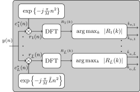
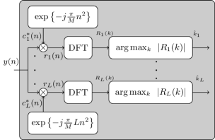
We obtain the non-coherent detector for LDMCSS by evaluating the maximum argument of |βˆ‘n=0Mβˆ’1y​(n)​sβˆ—β€‹(n)|superscriptsubscript𝑛0𝑀1𝑦𝑛superscriptπ‘ βˆ—π‘›\left|\sum_{n=0}^{M-1}y(n){s}^{\ast}(n)\right|, leading to the following dis-joint detection problem for the identification of even and odd FSs:

k^e,l~=arg​maxke⁑|Rl~​(k)|,subscript^π‘˜e~𝑙argsubscriptsubscriptπ‘˜esubscript𝑅~π‘™π‘˜\begin{split}\hat{k}_{\mathrm{e},\tilde{l}}=\mathrm{arg}\max_{k_{\mathrm{e}}}~{}\left|R_{\tilde{l}}(k)\right|,\end{split} (16)

and

k^o,l~=arg​maxko⁑|Rl~​(k)|,subscript^π‘˜o~𝑙argsubscriptsubscriptπ‘˜osubscript𝑅~π‘™π‘˜\begin{split}\hat{k}_{\mathrm{o},\tilde{l}}&=\mathrm{arg}\max_{k_{\mathrm{o}}}~{}\left|R_{\tilde{l}}(k)\right|,\end{split} (17)

respectively. LDMCSS non-coherent detector is illustrated in Fig. 6. To determine the even or the odd FS using the non-coherent detector, the maximum argument of the absolute of the DFT of rl~subscriptπ‘Ÿ~𝑙r_{\tilde{l}}, i.e., Rl~subscript𝑅~𝑙R_{\tilde{l}}.

III Orthogonality Analysis of the Proposed Schemes

In this section, we investigate the orthogonality of LCSS and LDMCSS symbols. To this end, we evaluate the inner product of 𝒔𝒔\boldsymbol{s} and 𝒔¯=[s¯​(0),s¯​(1),β‹―,s¯​(Mβˆ’1)]T¯𝒔superscript¯𝑠0¯𝑠1⋯¯𝑠𝑀1T\overline{\boldsymbol{s}}=\left[\overline{s}(0),\overline{s}(1),\cdots,\overline{s}(M-1)\right]^{\mathrm{T}} (the same symbol notations are considered for both LCSS and LDMCSS). The inner product is given as:

βŸ¨π’”,π’”Β―βŸ©=βˆ‘n=0Mβˆ’1s​(n)​sΒ―βˆ—β€‹(n).𝒔¯𝒔superscriptsubscript𝑛0𝑀1𝑠𝑛superscriptΒ―π‘ βˆ—π‘›\langle\boldsymbol{s},\overline{\boldsymbol{s}}\rangle=\sum_{n=0}^{M-1}s(n)\overline{s}^{\ast}(n). (18)

III-A Layered Chirp Spread Spectrum

For LCSS, we consider that the activated FS of a given layer in 𝒔𝒔\boldsymbol{s} and 𝒔¯¯𝒔\overline{\boldsymbol{s}} are klsubscriptπ‘˜π‘™k_{l} and kΒ―lΒ―subscriptΒ―π‘˜Β―π‘™\overline{k}_{\overline{l}}, respectively. 𝒔𝒔\boldsymbol{s} and 𝒔¯¯𝒔\overline{\boldsymbol{s}} have L𝐿L and LΒ―=L¯𝐿𝐿\overline{L}=L layers, respectively, with positive chirp rates of l𝑙l and l¯¯𝑙\overline{l}, where l=⟦1,LβŸ§π‘™1𝐿l=\llbracket 1,L\rrbracket and lΒ―=⟦1,LΒ―βŸ§Β―π‘™1¯𝐿\overline{l}=\llbracket 1,\overline{L}\rrbracket. To verify the orthogonality, the two symbols 𝒔𝒔\boldsymbol{s} and 𝒔¯¯𝒔\overline{\boldsymbol{s}} must have different activated FS, then, the inner product of 𝒔𝒔\boldsymbol{s} and 𝒔¯¯𝒔\overline{\boldsymbol{s}} yields:

βŸ¨π’”,π’”Β―βŸ©=βˆ‘l=1Lβˆ‘lΒ―=1LΒ―Ξ²(l,lΒ―),𝒔¯𝒔superscriptsubscript𝑙1𝐿superscriptsubscript¯𝑙1¯𝐿subscript𝛽𝑙¯𝑙\begin{split}&\langle\boldsymbol{s},\overline{\boldsymbol{s}}\rangle=\sum_{l=1}^{L}\sum_{\overline{l}=1}^{\overline{L}}\beta_{\left(l,\overline{l}\right)},\end{split} (19)

for lβ‰ l¯𝑙¯𝑙l\neq\overline{l}, with Ξ²(l,lΒ―)=βˆ‘n=0Mβˆ’1exp⁑{j​πM​(2​κ(l,lΒ―)​n+Ξ±(l,lΒ―)​n2)}subscript𝛽𝑙¯𝑙superscriptsubscript𝑛0𝑀1π‘—πœ‹π‘€2subscriptπœ…π‘™Β―π‘™π‘›subscript𝛼𝑙¯𝑙superscript𝑛2\beta_{\left(l,\overline{l}\right)}=\sum_{n=0}^{M-1}\exp\left\{j\frac{\pi}{M}\biggl{(}2\kappa_{\left(l,\overline{l}\right)}n+\alpha_{\left(l,\overline{l}\right)}n^{2}\biggr{)}\right\}, where ΞΊ(l,lΒ―)=klβˆ’kΒ―lΒ―subscriptπœ…π‘™Β―π‘™subscriptπ‘˜π‘™subscriptΒ―π‘˜Β―π‘™\kappa_{\left(l,\overline{l}\right)}=k_{l}-\overline{k}_{\overline{l}}, and Ξ±(l,lΒ―)=lβˆ’lΒ―subscript𝛼𝑙¯𝑙𝑙¯𝑙\alpha_{\left(l,\overline{l}\right)}=l-\overline{l}. Based on the layers, l𝑙l and l¯¯𝑙\overline{l}, Ξ±(l,lΒ―)subscript𝛼𝑙¯𝑙\alpha_{\left(l,\overline{l}\right)} ranges between βˆ’Mc+1≀α(l,lΒ―)≀Mc+1subscript𝑀c1subscript𝛼𝑙¯𝑙subscript𝑀c1-M_{\mathrm{c}}+1\leq\alpha_{\left(l,\overline{l}\right)}\leq M_{\mathrm{c}}+1. Since Ξ²(l,lΒ―)subscript𝛽𝑙¯𝑙\beta_{\left(l,\overline{l}\right)} in takes the form of generalized quadratic Gauss sum, therefore, we have Ξ²(l,lΒ―)=ΞΈ(l,lΒ―)​exp⁑{βˆ’j​2​πM​κ(l,lΒ―)2}​(1+Ξ³(l,lΒ―))subscript𝛽𝑙¯𝑙subscriptπœƒπ‘™Β―π‘™π‘—2πœ‹π‘€subscriptsuperscriptπœ…2𝑙¯𝑙1subscript𝛾𝑙¯𝑙\beta_{\left(l,\overline{l}\right)}=\theta_{\left(l,\overline{l}\right)}\exp\left\{-j\frac{2\pi}{M}\kappa^{2}_{\left(l,\overline{l}\right)}\right\}\left(1+\gamma_{\left(l,\overline{l}\right)}\right), where ΞΈ(l,lΒ―)=|MΞ±(l,lΒ―)|​exp⁑{j​π​|Ξ±(l,lΒ―)|4​α(l,lΒ―)}subscriptπœƒπ‘™Β―π‘™π‘€subscriptπ›Όπ‘™Β―π‘™π‘—πœ‹subscript𝛼𝑙¯𝑙4subscript𝛼𝑙¯𝑙\theta_{\left(l,\overline{l}\right)}=\sqrt{\left|\frac{M}{\alpha_{\left(l,\overline{l}\right)}}\right|}\exp\left\{j\frac{\pi|\alpha_{\left(l,\overline{l}\right)}|}{4\alpha_{\left(l,\overline{l}\right)}}\right\}. Moreover,

Ξ³(l,lΒ―)=βˆ‘n=0|Ξ±(l,lΒ―)|βˆ’1exp⁑{βˆ’j​πα(l,lΒ―)​(2​κ(l,lΒ―)​n+M​n2)}={1rem​(|ΞΊ(l,lΒ―)|,2)=0βˆ’1rem​(|ΞΊ(l,lΒ―)|,2)=1.subscript𝛾𝑙¯𝑙superscriptsubscript𝑛0subscript𝛼𝑙¯𝑙1π‘—πœ‹subscript𝛼𝑙¯𝑙2subscriptπœ…π‘™Β―π‘™π‘›π‘€superscript𝑛2cases1remsubscriptπœ…π‘™Β―π‘™201remsubscriptπœ…π‘™Β―π‘™21\begin{split}\gamma_{\left(l,\overline{l}\right)}&=\sum_{n=0}^{|\alpha_{\left(l,\overline{l}\right)}|-1}\exp\left\{-j\frac{\pi}{\alpha_{\left(l,\overline{l}\right)}}\left(2\kappa_{\left(l,\overline{l}\right)}n+Mn^{2}\right)\right\}\\ &=\begin{dcases}1&\quad\mathrm{rem}\left(|\kappa_{\left(l,\overline{l}\right)}|,2\right)=0\\ -1&\quad\mathrm{rem}\left(|\kappa_{\left(l,\overline{l}\right)}|,2\right)=1\\ \end{dcases}.\end{split} (20)

Depending on klsubscriptπ‘˜π‘™k_{l} and kΒ―lΒ―subscriptΒ―π‘˜Β―π‘™\overline{k}_{\overline{l}}, the value of Ξ³(l,lΒ―)subscript𝛾𝑙¯𝑙\gamma_{\left(l,\overline{l}\right)} is either 111 or βˆ’11-1. where rem​(x,y)remπ‘₯𝑦\mathrm{rem}\left(x,y\right) disseminates the remainder resulting from the division of xπ‘₯x from y𝑦y. In other words, if |ΞΊ(l,lΒ―)|subscriptπœ…π‘™Β―π‘™|\kappa_{\left(l,\overline{l}\right)}| is even, the value of Ξ³(l,lΒ―)subscript𝛾𝑙¯𝑙\gamma_{\left(l,\overline{l}\right)} is 111; otherwise, it is βˆ’11-1. Substituting Ξ²(l,lΒ―)subscript𝛽𝑙¯𝑙\beta_{\left(l,\overline{l}\right)} in (19), we attain:

βŸ¨π’”,π’”Β―βŸ©=βˆ‘l=1Lβˆ‘lΒ―=1LΒ―ΞΈ(l,lΒ―)​exp⁑{βˆ’j​2​πM​κ(l,lΒ―)2}​(1+Ξ³(l,lΒ―)),𝒔¯𝒔superscriptsubscript𝑙1𝐿superscriptsubscript¯𝑙1¯𝐿subscriptπœƒπ‘™Β―π‘™π‘—2πœ‹π‘€subscriptsuperscriptπœ…2𝑙¯𝑙1subscript𝛾𝑙¯𝑙\begin{split}\langle\boldsymbol{s},\overline{\boldsymbol{s}}\rangle&=\sum_{l=1}^{L}\sum_{\overline{l}=1}^{\overline{L}}\theta_{\left(l,\overline{l}\right)}\exp\left\{-j\frac{2\pi}{M}\kappa^{2}_{\left(l,\overline{l}\right)}\right\}\left(1+\gamma_{\left(l,\overline{l}\right)}\right),\end{split} (21)

for lβ‰ l¯𝑙¯𝑙l\neq\overline{l}. From (21), we observe that the LCSS symbols are not orthogonal because of the activation of different FSs in the layered structure. Even though the individual layers (with different activated FSs) may be orthogonal to each other; however, the composite symbol as a whole is not orthogonal to another LCSS symbol with different activated FSs. The two symbols can only be orthogonal if and only if all |ΞΊ(l,lΒ―)|subscriptπœ…π‘™Β―π‘™|\kappa_{\left(l,\overline{l}\right)}| is odd βˆ€{l,lΒ―}for-all𝑙¯𝑙\forall~{}\{l,\overline{l}\}, as it would result in Ξ³(l,lΒ―)=βˆ’1subscript𝛾𝑙¯𝑙1\gamma_{\left(l,\overline{l}\right)}=-1.

III-B Layered Dual-Mode Chirp Spread Spectrum

In LDMCSS, the even and the odd FSs of 𝒔𝒔\boldsymbol{s} are ke,l~subscriptπ‘˜e~𝑙k_{\mathrm{e},\tilde{l}} and ko,l~subscriptπ‘˜o~𝑙k_{\mathrm{o},\tilde{l}}, respectively. Similarly, for 𝒔¯¯𝒔\overline{\boldsymbol{s}}, the even and the odd FSs are kΒ―e,l~Β―subscriptΒ―π‘˜eΒ―~𝑙\overline{k}_{\mathrm{e},\overline{\tilde{l}}} and kΒ―o,l~Β―subscriptΒ―π‘˜oΒ―~𝑙\overline{k}_{\mathrm{o},\overline{\tilde{l}}}, respectively. We consider that both 𝒔𝒔\boldsymbol{s} and 𝒔¯¯𝒔\overline{\boldsymbol{s}} have L~~𝐿\tilde{L} and L~Β―Β―~𝐿\overline{\tilde{L}} layers, respectively, having positive chirp rates of l~~𝑙\tilde{l} and l~Β―Β―~𝑙\overline{\tilde{l}}, where l~=⟦1,L~⟧~𝑙1~𝐿\tilde{l}=\llbracket 1,\tilde{L}\rrbracket and l~Β―=⟦1,L~¯⟧¯~𝑙1Β―~𝐿\overline{\tilde{l}}=\llbracket 1,\overline{\tilde{L}}\rrbracket. The following conditions must hold to determine the orthogonality of LDMCSS symbols: (i) the even FS in the l𝑙lth layer of 𝒔𝒔\boldsymbol{s}, i.e., ke,l~subscriptπ‘˜e~𝑙k_{\mathrm{e},\tilde{l}} is different from the even FS of l¯¯𝑙\overline{l}th layer of 𝒔¯¯𝒔\overline{\boldsymbol{s}}, i.e., kΒ―e,l~Β―subscriptΒ―π‘˜eΒ―~𝑙\overline{k}_{\mathrm{e},\overline{\tilde{l}}}, where l~=l~Β―~𝑙¯~𝑙\tilde{l}=\overline{\tilde{l}}; and (ii) considering the same layer of 𝒔𝒔\boldsymbol{s} and 𝒔¯¯𝒔\overline{\boldsymbol{s}}, i.e., l~=l~Β―~𝑙¯~𝑙\tilde{l}=\overline{\tilde{l}}, the odd FS in 𝒔𝒔\boldsymbol{s}, ko,l~subscriptπ‘˜o~𝑙k_{\mathrm{o},\tilde{l}} should be different from the odd FS of 𝒔¯¯𝒔\overline{\boldsymbol{s}}, kΒ―o,l~Β―subscriptΒ―π‘˜oΒ―~𝑙\overline{k}_{\mathrm{o},\overline{\tilde{l}}}. The inner product of 𝒔𝒔\boldsymbol{s} and 𝒔¯¯𝒔\overline{\boldsymbol{s}} for LDMCSS is given as:

βŸ¨π’”,π’”Β―βŸ©=βˆ‘l=1Lβˆ‘lΒ―=1LΒ―(Ξ²e​(l~,l~Β―)+Ξ²o​(l~,l~Β―)),𝒔¯𝒔superscriptsubscript𝑙1𝐿superscriptsubscript¯𝑙1¯𝐿subscript𝛽e~𝑙¯~𝑙subscript𝛽o~𝑙¯~𝑙\begin{split}\langle\boldsymbol{s},\overline{\boldsymbol{s}}\rangle=\sum_{l=1}^{L}\sum_{\overline{l}=1}^{\overline{L}}\biggl{(}{\beta}_{\mathrm{e}\left(\tilde{l},\overline{\tilde{l}}\right)}+{\beta}_{\mathrm{o}\left(\tilde{l},\overline{\tilde{l}}\right)}\biggr{)},\end{split} (22)

for lβ‰ l¯𝑙¯𝑙l\neq\overline{l}, where Ξ²e​(l~,l~Β―)=βˆ‘n=0Mβˆ’1exp⁑{j​πM​(2​κe​(l~,l~Β―)​n+Ξ±~(l~,l~Β―)​n2)}subscript𝛽e~𝑙¯~𝑙superscriptsubscript𝑛0𝑀1π‘—πœ‹π‘€2subscriptπœ…e~𝑙¯~𝑙𝑛subscript~𝛼~𝑙¯~𝑙superscript𝑛2\small{{\beta}_{\mathrm{e}\left(\tilde{l},\overline{\tilde{l}}\right)}=\sum_{n=0}^{M-1}\exp\left\{j\frac{\pi}{M}\biggl{(}2\kappa_{\mathrm{e}\left(\tilde{l},\overline{\tilde{l}}\right)}n+\tilde{\alpha}_{\left(\tilde{l},\overline{\tilde{l}}\right)}n^{2}\biggr{)}\right\}}, and Ξ²o​(l~,l~Β―)=βˆ‘n=0Mβˆ’1exp⁑{j​πM​(2​κo​(l~,l~Β―)​n+Ξ±~(l~,l~Β―)​n2)}subscript𝛽o~𝑙¯~𝑙superscriptsubscript𝑛0𝑀1π‘—πœ‹π‘€2subscriptπœ…o~𝑙¯~𝑙𝑛subscript~𝛼~𝑙¯~𝑙superscript𝑛2\small{{\beta}_{\mathrm{o}\left(\tilde{l},\overline{\tilde{l}}\right)}=\sum_{n=0}^{M-1}\exp\left\{j\frac{\pi}{M}\biggl{(}2\kappa_{\mathrm{o}\left(\tilde{l},\overline{\tilde{l}}\right)}n+\tilde{\alpha}_{\left(\tilde{l},\overline{\tilde{l}}\right)}n^{2}\biggr{)}\right\}}, where ΞΊe​(l~,l~Β―)=ke,l~βˆ’kΒ―e,l~Β―subscriptπœ…e~𝑙¯~𝑙subscriptπ‘˜e~𝑙subscriptΒ―π‘˜eΒ―~𝑙\kappa_{\mathrm{e}\left(\tilde{l},\overline{\tilde{l}}\right)}=k_{\mathrm{e},\tilde{l}}-\overline{k}_{\mathrm{e},\overline{\tilde{l}}}, ΞΊo​(l~,l~Β―)=ko,l~βˆ’kΒ―o,l~Β―subscriptπœ…o~𝑙¯~𝑙subscriptπ‘˜o~𝑙subscriptΒ―π‘˜oΒ―~𝑙\kappa_{\mathrm{o}\left(\tilde{l},\overline{\tilde{l}}\right)}=k_{\mathrm{o},\tilde{l}}-\overline{k}_{\mathrm{o},\overline{\tilde{l}}}, and Ξ±~(l~,l~Β―)=l~βˆ’l~Β―subscript~𝛼~𝑙¯~𝑙~𝑙¯~𝑙\tilde{\alpha}_{\left(\tilde{l},\overline{\tilde{l}}\right)}=\tilde{l}-\overline{\tilde{l}}. Note that Ξ±~(l~,l~Β―)subscript~𝛼~𝑙¯~𝑙\tilde{\alpha}_{\left(\tilde{l},\overline{\tilde{l}}\right)} is bounded between βˆ’M~c+1≀α~(l~,l~Β―)≀M~cβˆ’1subscript~𝑀c1subscript~𝛼~𝑙¯~𝑙subscript~𝑀c1-\tilde{M}_{\mathrm{c}}+1\leq\tilde{\alpha}_{\left(\tilde{l},\overline{\tilde{l}}\right)}\leq\tilde{M}_{\mathrm{c}}-1. It is recalled that the number of chirp rates in LDMCSS is half relative to the chirp rates used in LCSS, i.e., Mc=M~c/2subscript𝑀csubscript~𝑀c2M_{\mathrm{c}}=\nicefrac{{\tilde{M}_{\mathrm{c}}}}{{2}}.

We can attain closed-form expressions for Ξ²e​(l~,l~Β―)subscript𝛽e~𝑙¯~𝑙{\beta}_{\mathrm{e}\left(\tilde{l},\overline{\tilde{l}}\right)} and Ξ²o​(l~,l~Β―)subscript𝛽o~𝑙¯~𝑙{\beta}_{\mathrm{o}\left(\tilde{l},\overline{\tilde{l}}\right)} using the generalized quadratic Gauss sum as Ξ²e​(l~,l~Β―)=ΞΈ~(l~,l~Β―)​exp⁑{βˆ’j​2​πM​κe2​(l~,l~Β―)}​(1+Ξ³e​(l,lΒ―))subscript𝛽e~𝑙¯~𝑙subscript~πœƒ~𝑙¯~𝑙𝑗2πœ‹π‘€subscriptπœ…superscripte2~𝑙¯~𝑙1subscript𝛾e𝑙¯𝑙\small{\beta_{\mathrm{e}\left(\tilde{l},\overline{\tilde{l}}\right)}=\tilde{\theta}_{\left(\tilde{l},\overline{\tilde{l}}\right)}\exp\left\{-j\frac{2\pi}{M}\kappa_{\mathrm{e}^{2}\left(\tilde{l},\overline{\tilde{l}}\right)}\right\}\left(1+\gamma_{\mathrm{e}\left(l,\overline{l}\right)}\right)}, and Ξ²o​(l~,l~Β―)=ΞΈ~(l~,l~Β―)​exp⁑{βˆ’j​2​πM​κo2​(l~,l~Β―)}​(1+Ξ³o​(l,lΒ―))subscript𝛽o~𝑙¯~𝑙subscript~πœƒ~𝑙¯~𝑙𝑗2πœ‹π‘€subscriptπœ…superscripto2~𝑙¯~𝑙1subscript𝛾o𝑙¯𝑙\small{\beta_{\mathrm{o}\left(\tilde{l},\overline{\tilde{l}}\right)}=\tilde{\theta}_{\left(\tilde{l},\overline{\tilde{l}}\right)}\exp\left\{-j\frac{2\pi}{M}\kappa_{\mathrm{o}^{2}\left(\tilde{l},\overline{\tilde{l}}\right)}\right\}\left(1+\gamma_{\mathrm{o}\left(l,\overline{l}\right)}\right)}, respectively, where ΞΈ~(l~,l~Β―)=|MΞ±~(l~,l~Β―)|​exp⁑{j​π​|Ξ±~(l~,l~Β―)|4​α~(l~,l~Β―)}subscript~πœƒ~𝑙¯~𝑙𝑀subscript~𝛼~𝑙¯~π‘™π‘—πœ‹subscript~𝛼~𝑙¯~𝑙4subscript~𝛼~𝑙¯~𝑙\tilde{\theta}_{\left(\tilde{l},\overline{\tilde{l}}\right)}=\sqrt{\left|\frac{M}{\tilde{\alpha}_{\left(\tilde{l},\overline{\tilde{l}}\right)}}\right|}\exp\left\{j\frac{\pi|\tilde{\alpha}_{\left(\tilde{l},\overline{\tilde{l}}\right)}|}{4\tilde{\alpha}_{\left(\tilde{l},\overline{\tilde{l}}\right)}}\right\}. Let us consider a parameter Ξ³(β‹…)​(l,lΒ―)subscript𝛾⋅𝑙¯𝑙\gamma_{(\cdot)\left(l,\overline{l}\right)}, which can be used for either Ξ³e​(l,lΒ―)subscript𝛾e𝑙¯𝑙\gamma_{\mathrm{e}\left(l,\overline{l}\right)} and Ξ³o​(l,lΒ―)subscript𝛾o𝑙¯𝑙\gamma_{\mathrm{o}\left(l,\overline{l}\right)}. Ξ³(β‹…)​(l,lΒ―)subscript𝛾⋅𝑙¯𝑙\gamma_{(\cdot)\left(l,\overline{l}\right)} is given as:

Ξ³(β‹…)​(l~,l~Β―)=βˆ‘n=0|Ξ±~(l~,l~Β―)|βˆ’1exp⁑{βˆ’j​πα~(l~,l~Β―)​(2​κ(β‹…)​(l~,l~Β―)​n+M​n2)}={1rem​(|ΞΊ(β‹…)​(l~,l~Β―)|,2)=0βˆ’1rem​(|ΞΊ(β‹…)​(l~,l~Β―)|,2)=1,subscript𝛾⋅~𝑙¯~𝑙superscriptsubscript𝑛0subscript~𝛼~𝑙¯~𝑙1π‘—πœ‹subscript~𝛼~𝑙¯~𝑙2subscriptπœ…β‹…~𝑙¯~𝑙𝑛𝑀superscript𝑛2cases1remsubscriptπœ…β‹…~𝑙¯~𝑙201remsubscriptπœ…β‹…~𝑙¯~𝑙21\begin{split}\gamma_{(\cdot)\left(\tilde{l},\overline{\tilde{l}}\right)}&=\sum_{n=0}^{|\tilde{\alpha}_{\left(\tilde{l},\overline{\tilde{l}}\right)}|-1}\exp\left\{-j\frac{\pi}{\tilde{\alpha}_{\left(\tilde{l},\overline{\tilde{l}}\right)}}\left(2\kappa_{(\cdot)\left(\tilde{l},\overline{\tilde{l}}\right)}n+Mn^{2}\right)\right\}\\ &=\begin{dcases}1&\quad\mathrm{rem}\left(|\kappa_{(\cdot)\left(\tilde{l},\overline{\tilde{l}}\right)}|,2\right)=0\\ -1&\quad\mathrm{rem}\left(|\kappa_{(\cdot)\left(\tilde{l},\overline{\tilde{l}}\right)}|,2\right)=1\\ \end{dcases},\end{split} (23)

Ξ³e​(l~,l~Β―)subscript𝛾e~𝑙¯~𝑙\gamma_{\mathrm{e}\left(\tilde{l},\overline{\tilde{l}}\right)} and Ξ³o​(l~,l~Β―)subscript𝛾o~𝑙¯~𝑙\gamma_{\mathrm{o}\left(\tilde{l},\overline{\tilde{l}}\right)} can be either 111 or βˆ’11-1 depending on ΞΊe​(l~,l~Β―)subscriptπœ…e~𝑙¯~𝑙\kappa_{\mathrm{e}\left(\tilde{l},\overline{\tilde{l}}\right)} and ΞΊo​(l~,l~Β―)subscriptπœ…o~𝑙¯~𝑙\kappa_{\mathrm{o}\left(\tilde{l},\overline{\tilde{l}}\right)}. Then, βŸ¨π’”,π’”Β―βŸ©π’”Β―π’”\langle\boldsymbol{s},\overline{\boldsymbol{s}}\rangle can be obtained as:

βŸ¨π’”,π’”Β―βŸ©=βˆ‘l=1Lβˆ‘lΒ―=1LΒ―ΞΈ~(l~,l~Β―)(exp{βˆ’j2​πMΞΊe2​(l~,l~Β―)}(1+Ξ³e​(l,lΒ―))+exp{βˆ’j2​πMΞΊo2​(l~,l~Β―)}(1+Ξ³o​(l,lΒ―))),𝒔¯𝒔superscriptsubscript𝑙1𝐿superscriptsubscript¯𝑙1¯𝐿subscript~πœƒ~𝑙¯~𝑙𝑗2πœ‹π‘€subscriptπœ…superscripte2~𝑙¯~𝑙1subscript𝛾e𝑙¯𝑙𝑗2πœ‹π‘€subscriptπœ…superscripto2~𝑙¯~𝑙1subscript𝛾o𝑙¯𝑙\begin{split}\langle\boldsymbol{s},\overline{\boldsymbol{s}}\rangle&=\sum_{l=1}^{L}\sum_{\overline{l}=1}^{\overline{L}}\tilde{\theta}_{\left(\tilde{l},\overline{\tilde{l}}\right)}\left(\exp\left\{-j\frac{2\pi}{M}\kappa_{\mathrm{e}^{2}\left(\tilde{l},\overline{\tilde{l}}\right)}\right\}\left(1+\gamma_{\mathrm{e}\left(l,\overline{l}\right)}\right)\right.\\ &~{}~{}~{}\left.+\exp\left\{-j\frac{2\pi}{M}\kappa_{\mathrm{o}^{2}\left(\tilde{l},\overline{\tilde{l}}\right)}\right\}\left(1+\gamma_{\mathrm{o}\left(l,\overline{l}\right)}\right)\right),\end{split} (24)

for l~β‰ l~Β―~𝑙¯~𝑙\tilde{l}\neq\overline{\tilde{l}}. From (24), we gather that, like LCSS, LDMCSS symbols are also not orthogonal even though the individual layers (with different activated even and odd FSs) are orthogonal to each other. This loss in orthogonality is due to the activation of multiple activated even and odd FSs.

IV Interference Analysis of the Proposed Schemes

In this section, we analytically evaluate the interference for LCSS, and LDMCSS caused due to their layered structure. The interference results from activating multiple FSs in the different layers. The analysis considers a simple AWGN channel without loss of generality. To this end, we consider that the received symbol after multiplication with a down-chirp symbol having a chirp rate of l¯¯𝑙\overline{l} is

rl¯​(n)=(s​(n)+w​(n))​clΒ―βˆ—β€‹(n)=s​(n)​clΒ―βˆ—β€‹(n)+w¯​(n),subscriptπ‘ŸΒ―π‘™π‘›π‘ π‘›π‘€π‘›superscriptsubscriptπ‘Β―π‘™βˆ—π‘›π‘ π‘›superscriptsubscriptπ‘Β―π‘™βˆ—π‘›Β―π‘€π‘›\begin{split}r_{\overline{l}}(n)&=\bigl{(}s(n)+w(n)\bigr{)}c_{\overline{l}}^{\ast}(n)=s(n)c_{\overline{l}}^{\ast}(n)+\overline{w}(n),\end{split} (25)

where w¯​(n)=w​(n)​clΒ―βˆ—β€‹(n)¯𝑀𝑛𝑀𝑛superscriptsubscriptπ‘Β―π‘™βˆ—π‘›\overline{w}(n)=w(n)c_{\overline{l}}^{\ast}(n) are the samples of AWGN multiplied with the down-chirp symbol.

In the sequel, we present the interference analysis of both LCSS and LDMCSS separately.

IV-A Layered Chirp Spread Spectrum

The down-chirped received symbol for LCSS is given as:

rl¯​(n)=βˆ‘l=1Lexp⁑{j​πM​(2​kl​n+Ξ±(l,lΒ―)​n2)}+w¯​(n).subscriptπ‘ŸΒ―π‘™π‘›superscriptsubscript𝑙1πΏπ‘—πœ‹π‘€2subscriptπ‘˜π‘™π‘›subscript𝛼𝑙¯𝑙superscript𝑛2¯𝑀𝑛\begin{split}r_{\overline{l}}(n)=\sum_{l=1}^{L}\exp\left\{j\frac{\pi}{M}\biggl{(}2k_{l}n+\alpha_{\left(l,\overline{l}\right)}n^{2}\biggr{)}\right\}+\overline{w}(n).\end{split} (26)

It is recalled that in the LCSS symbol, the activated FS at the l𝑙lth layer is klsubscriptπ‘˜π‘™k_{l} and is chirped at rate l𝑙l. When the chirp rate of the down-chirp symbol and the layer number match, i.e., lΒ―=l¯𝑙𝑙\overline{l}=l, then from (26), we have:

rl¯​(n)=exp⁑{j​2​πM​kl​n}+βˆ‘l=1lβ‰ lΒ―Lexp⁑{j​πM​(2​kl​n+Ξ±(l,lΒ―)​n2)}+w¯​(n).subscriptπ‘ŸΒ―π‘™π‘›π‘—2πœ‹π‘€subscriptπ‘˜π‘™π‘›superscriptsubscript𝑙1π‘™Β―π‘™πΏπ‘—πœ‹π‘€2subscriptπ‘˜π‘™π‘›subscript𝛼𝑙¯𝑙superscript𝑛2¯𝑀𝑛\begin{split}r_{\overline{l}}(n)=&\exp\left\{j\frac{2\pi}{M}k_{l}n\right\}+\sum_{\begin{subarray}{c}l=1\\ l\neq\overline{l}\end{subarray}}^{L}\exp\left\{j\frac{\pi}{M}\biggl{(}2k_{l}n+\alpha_{\left(l,\overline{l}\right)}n^{2}\biggr{)}\right\}\\ &~{}+\overline{w}(n).\end{split} (27)

The first term in (27) follows from the fact that l=l¯𝑙¯𝑙l=\overline{l}, whereas the second term incorporates interference caused by the remaining layers.

Performing M𝑀M-order DFT on rl¯​(n)subscriptπ‘ŸΒ―π‘™π‘›r_{\overline{l}}(n) in (27) results in:

Rl¯​(k)=βˆ‘n=0Mβˆ’1exp⁑{j​πM​(2​klβˆ’k)​n}+βˆ‘l=1lβ‰ lΒ―LΞ²1​(l,lΒ―)+W¯​(k),subscriptπ‘…Β―π‘™π‘˜superscriptsubscript𝑛0𝑀1π‘—πœ‹π‘€2subscriptπ‘˜π‘™π‘˜π‘›superscriptsubscript𝑙1𝑙¯𝑙𝐿subscript𝛽1π‘™Β―π‘™Β―π‘Šπ‘˜\begin{split}R_{\overline{l}}(k)&=\sum_{n=0}^{M-1}\exp\left\{j\frac{\pi}{M}\biggl{(}2k_{l}-k\biggr{)}n\right\}+\sum_{\begin{subarray}{c}l=1\\ l\neq\overline{l}\end{subarray}}^{L}\beta_{1\left(l,\overline{l}\right)}+\overline{W}(k),\end{split} (28)

where, Ξ²1​(l,lΒ―)=βˆ‘n=0Mβˆ’1exp⁑{j​πM​(2​κ1​(l)​n+Ξ±(l,lΒ―)​n2)}subscript𝛽1𝑙¯𝑙superscriptsubscript𝑛0𝑀1π‘—πœ‹π‘€2subscriptπœ…1𝑙𝑛subscript𝛼𝑙¯𝑙superscript𝑛2\beta_{1\left(l,\overline{l}\right)}=\sum_{n=0}^{M-1}\exp\left\{j\frac{\pi}{M}\biggl{(}2\kappa_{1\left(l\right)}n+\alpha_{\left(l,\overline{l}\right)}n^{2}\biggr{)}\right\} with ΞΊ1​(l)=klβˆ’ksubscriptπœ…1𝑙subscriptπ‘˜π‘™π‘˜\kappa_{1\left(l\right)}=k_{l}-k. When k=klπ‘˜subscriptπ‘˜π‘™k=k_{l}, then the first term in (28) equates to M𝑀M. Moreover, we can attain a closed-form expression for Ξ²1​(l,lΒ―)subscript𝛽1𝑙¯𝑙\beta_{1\left(l,\overline{l}\right)} using generalized quadratic Gauss sum as Ξ²1​(l,lΒ―)=ΞΈ(l,lΒ―)​exp⁑{j​2​πM​κ1​(l)2}​(1+Ξ³1​(l,lΒ―))subscript𝛽1𝑙¯𝑙subscriptπœƒπ‘™Β―π‘™π‘—2πœ‹π‘€subscriptsuperscriptπœ…21𝑙1subscript𝛾1𝑙¯𝑙\beta_{1\left(l,\overline{l}\right)}=\theta_{\left(l,\overline{l}\right)}\exp\left\{j\frac{2\pi}{M}\kappa^{2}_{1(l)}\right\}\bigl{(}1+\gamma_{1\left(l,\overline{l}\right)}\bigr{)} where

Ξ³1​(l,lΒ―)=βˆ‘n=0|Ξ±(l,lΒ―)|βˆ’1exp⁑{βˆ’j​πα(l,lΒ―)​(2​κ1​(l)​n+M​n2)}={1rem​(|ΞΊ1​(l)|,2)=0βˆ’1rem​(|ΞΊ1​(l)|,2)=1,subscript𝛾1𝑙¯𝑙superscriptsubscript𝑛0subscript𝛼𝑙¯𝑙1π‘—πœ‹subscript𝛼𝑙¯𝑙2subscriptπœ…1𝑙𝑛𝑀superscript𝑛2cases1remsubscriptπœ…1𝑙201remsubscriptπœ…1𝑙21\begin{split}\gamma_{1\left(l,\overline{l}\right)}&=\sum_{n=0}^{|\alpha_{\left(l,\overline{l}\right)}|-1}\exp\left\{-j\frac{\pi}{\alpha_{\left(l,\overline{l}\right)}}\left(2\kappa_{1\left(l\right)}n+Mn^{2}\right)\right\}\\ &=\begin{dcases}1&\quad\mathrm{rem}\left(|\kappa_{1\left(l\right)}|,2\right)=0\\ -1&\quad\mathrm{rem}\left(|\kappa_{1\left(l\right)}|,2\right)=1\\ \end{dcases},\end{split} (29)

Ξ³1​(l,lΒ―)subscript𝛾1𝑙¯𝑙\gamma_{1\left(l,\overline{l}\right)} is either 111 or βˆ’11-1, and its value depends on whether |ΞΊ1​(l)|subscriptπœ…1𝑙|\kappa_{1\left(l\right)}| is even or odd.

Finally, (28) can be re-written as:

Rl¯​(k)=M⏟Signal+βˆ‘l=1lβ‰ lΒ―LΞ²1​(l,lΒ―)⏟Interference+W¯​(k)⏟Noise,subscriptπ‘…Β―π‘™π‘˜subscriptβŸπ‘€Signalsubscript⏟superscriptsubscript𝑙1𝑙¯𝑙𝐿subscript𝛽1𝑙¯𝑙InterferencesubscriptβŸΒ―π‘Šπ‘˜Noise\begin{split}R_{\overline{l}}(k)&=\underbrace{M}_{\mathrm{Signal}}+\underbrace{\sum_{\begin{subarray}{c}l=1\\ l\neq\overline{l}\end{subarray}}^{L}\beta_{1\left(l,\overline{l}\right)}}_{\mathrm{Interference}}+\underbrace{\overline{W}(k)}_{\mathrm{Noise}},\end{split} (30)

We can gather from (30) that apart from the intended signal at a given layer, the FSs on the remaining layers contribute towards the interference. Moreover, (30) also implies that increasing M𝑀M would increase the signal-to-interference ratio for the same number of layers.

IV-B Layered Dual-Mode Chirp Spread Spectrum

The down-chirped LDMCSS received symbol is given as:

rl¯​(n)=βˆ‘l~=1Lexp⁑{j​πM​(2​ke,l~​n+Ξ±Β―(l~,lΒ―)​n2)}+βˆ‘l~=1Lexp⁑{j​πM​(2​ko,l~​n+Ξ±Β―(l~,lΒ―)​n2)}+w¯​(n),subscriptπ‘ŸΒ―π‘™π‘›superscriptsubscript~𝑙1πΏπ‘—πœ‹π‘€2subscriptπ‘˜e~𝑙𝑛subscript¯𝛼~𝑙¯𝑙superscript𝑛2superscriptsubscript~𝑙1πΏπ‘—πœ‹π‘€2subscriptπ‘˜o~𝑙𝑛subscript¯𝛼~𝑙¯𝑙superscript𝑛2¯𝑀𝑛\begin{split}r_{\overline{l}}(n)&=\sum_{\tilde{l}=1}^{L}\exp\left\{j\frac{\pi}{M}\biggl{(}2k_{\mathrm{e},\tilde{l}}n+\overline{\alpha}_{\left(\tilde{l},\overline{l}\right)}n^{2}\biggr{)}\right\}\\ &~{}+\sum_{\tilde{l}=1}^{L}\exp\left\{j\frac{\pi}{M}\biggl{(}2k_{\mathrm{o},\tilde{l}}n+\overline{\alpha}_{\left(\tilde{l},\overline{l}\right)}n^{2}\biggr{)}\right\}+\overline{w}(n),\end{split} (31)

where Ξ±Β―(l~,lΒ―)=l~βˆ’lΒ―subscript¯𝛼~𝑙¯𝑙~𝑙¯𝑙\overline{\alpha}_{\left(\tilde{l},\overline{l}\right)}=\tilde{l}-\overline{l}. LDMCSS symbols at l~~𝑙\tilde{l}th layer use a chirp rate of l~~𝑙\tilde{l}, and the even and odd FSs are ke,l~subscriptπ‘˜e~𝑙k_{\mathrm{e},\tilde{l}} and ko,l~subscriptπ‘˜o~𝑙k_{\mathrm{o},\tilde{l}}. When the chirp rate of down-chirp symbol matches the chirp rate used in the l~~𝑙\tilde{l}th layer, i.e., l~=lΒ―~𝑙¯𝑙\tilde{l}=\overline{l}, then (31) can be re-written as:

rl¯​(n)=exp⁑{j​2​πM​ke,l~}+exp⁑{j​2​πM​ko,l~}+βˆ‘l~=1l~β‰ lΒ―L~exp⁑{j​πM​(2​ke,l~​n+Ξ±Β―(l~,lΒ―)​n2)}+βˆ‘l~=1l~β‰ lΒ―L~exp⁑{j​πM​(2​ko,l~​n+Ξ±Β―(l~,lΒ―)​n2)}+w¯​(n).subscriptπ‘ŸΒ―π‘™π‘›π‘—2πœ‹π‘€subscriptπ‘˜e~𝑙𝑗2πœ‹π‘€subscriptπ‘˜o~𝑙superscriptsubscript~𝑙1~𝑙¯𝑙~πΏπ‘—πœ‹π‘€2subscriptπ‘˜e~𝑙𝑛subscript¯𝛼~𝑙¯𝑙superscript𝑛2superscriptsubscript~𝑙1~𝑙¯𝑙~πΏπ‘—πœ‹π‘€2subscriptπ‘˜o~𝑙𝑛subscript¯𝛼~𝑙¯𝑙superscript𝑛2¯𝑀𝑛\begin{split}r_{\overline{l}}(n)&=\exp\left\{j\frac{2\pi}{M}k_{\mathrm{e},\tilde{l}}\right\}+\exp\left\{j\frac{2\pi}{M}k_{\mathrm{o},\tilde{l}}\right\}\\ &~{}+\sum_{\begin{subarray}{c}\tilde{l}=1\\ \tilde{l}\neq\overline{l}\end{subarray}}^{\tilde{L}}\exp\left\{j\frac{\pi}{M}\biggl{(}2k_{\mathrm{e},\tilde{l}}n+\overline{\alpha}_{\left(\tilde{l},\overline{l}\right)}n^{2}\biggr{)}\right\}\\ &~{}+\sum_{\begin{subarray}{c}\tilde{l}=1\\ \tilde{l}\neq\overline{l}\end{subarray}}^{\tilde{L}}\exp\left\{j\frac{\pi}{M}\biggl{(}2k_{\mathrm{o},\tilde{l}}n+\overline{\alpha}_{\left(\tilde{l},\overline{l}\right)}n^{2}\biggr{)}\right\}+\overline{w}(n).\end{split} (32)

The second and third terms in (32) indicate the interference caused by the layered structure in LDMCSS. Performing M𝑀M-order DFT on rl¯​(n)subscriptπ‘ŸΒ―π‘™π‘›r_{\overline{l}}(n) in (32), we attain:

Rl¯​(k)=βˆ‘n=0Mβˆ’1exp⁑{j​πM​(2​ke,l~βˆ’k)​n}+βˆ‘n=0Mβˆ’1exp⁑{j​πM​(2​ko,l~βˆ’k)​n}+βˆ‘l~=1l~β‰ lΒ―L~(Ξ²Β―e​(l~,lΒ―)+Ξ²Β―o​(l~,lΒ―))+W¯​(k),subscriptπ‘…Β―π‘™π‘˜superscriptsubscript𝑛0𝑀1π‘—πœ‹π‘€2subscriptπ‘˜e~π‘™π‘˜π‘›superscriptsubscript𝑛0𝑀1π‘—πœ‹π‘€2subscriptπ‘˜o~π‘™π‘˜π‘›superscriptsubscript~𝑙1~𝑙¯𝑙~𝐿subscript¯𝛽e~𝑙¯𝑙subscript¯𝛽o~π‘™Β―π‘™Β―π‘Šπ‘˜\begin{split}R_{\overline{l}}(k)&=\sum_{n=0}^{M-1}\exp\left\{j\frac{\pi}{M}\biggl{(}2k_{\mathrm{e},\tilde{l}}-k\biggr{)}n\right\}+\\ &\sum_{n=0}^{M-1}\exp\left\{j\frac{\pi}{M}\biggl{(}2k_{\mathrm{o},\tilde{l}}-k\biggr{)}n\right\}\\ &~{}+\sum_{\begin{subarray}{c}\tilde{l}=1\\ \tilde{l}\neq\overline{l}\end{subarray}}^{\tilde{L}}\biggl{(}\overline{\beta}_{\mathrm{e}\left(\tilde{l},\overline{l}\right)}+\overline{\beta}_{\mathrm{o}\left(\tilde{l},\overline{l}\right)}\biggr{)}+\overline{W}(k),\end{split} (33)

where Ξ²Β―e​(l~,lΒ―)=βˆ‘n=0Mβˆ’1exp⁑{j​πM​(2​κ¯e​(l~)​n+Ξ±Β―(l~,lΒ―)​n2)}subscript¯𝛽e~𝑙¯𝑙superscriptsubscript𝑛0𝑀1π‘—πœ‹π‘€2subscriptΒ―πœ…e~𝑙𝑛subscript¯𝛼~𝑙¯𝑙superscript𝑛2\overline{\beta}_{\mathrm{e}\left(\tilde{l},\overline{l}\right)}=\sum_{n=0}^{M-1}\exp\left\{j\frac{\pi}{M}\biggl{(}2\overline{\kappa}_{\mathrm{e}\left(\tilde{l}\right)}n+\overline{\alpha}_{\left(\tilde{l},\overline{l}\right)}n^{2}\biggr{)}\right\}, and Ξ²Β―o​(l~,lΒ―)=βˆ‘n=0Mβˆ’1exp⁑{j​πM​(2​κ¯o​(l~)​n+Ξ±Β―(l~,lΒ―)​n2)}subscript¯𝛽o~𝑙¯𝑙superscriptsubscript𝑛0𝑀1π‘—πœ‹π‘€2subscriptΒ―πœ…o~𝑙𝑛subscript¯𝛼~𝑙¯𝑙superscript𝑛2\overline{\beta}_{\mathrm{o}\left(\tilde{l},\overline{l}\right)}=\sum_{n=0}^{M-1}\exp\left\{j\frac{\pi}{M}\biggl{(}2\overline{\kappa}_{\mathrm{o}\left(\tilde{l}\right)}n+\overline{\alpha}_{\left(\tilde{l},\overline{l}\right)}n^{2}\biggr{)}\right\}. ΞΊΒ―e​(l~)=ke,l~βˆ’ksubscriptΒ―πœ…e~𝑙subscriptπ‘˜e~π‘™π‘˜\overline{\kappa}_{\mathrm{e}\left(\tilde{l}\right)}=k_{\mathrm{e},\tilde{l}}-k, and ΞΊΒ―o​(l~)=ko,l~βˆ’ksubscriptΒ―πœ…o~𝑙subscriptπ‘˜o~π‘™π‘˜\overline{\kappa}_{\mathrm{o}\left(\tilde{l}\right)}=k_{\mathrm{o},\tilde{l}}-k. The closed-form expressions for Ξ²Β―e​(l~,lΒ―)subscript¯𝛽e~𝑙¯𝑙\overline{\beta}_{\mathrm{e}\left(\tilde{l},\overline{l}\right)} and Ξ²Β―o​(l~,lΒ―)subscript¯𝛽o~𝑙¯𝑙\overline{\beta}_{\mathrm{o}\left(\tilde{l},\overline{l}\right)} can be obtained by using generalized quadratic Gauss sum as Ξ²Β―e​(l~,lΒ―)=ΞΈΒ―(l~,lΒ―)​exp⁑{j​2​πM​κe​(l~)2}​(1+Ξ³Β―e​(l~,lΒ―))subscript¯𝛽e~𝑙¯𝑙subscriptΒ―πœƒ~𝑙¯𝑙𝑗2πœ‹π‘€subscriptsuperscriptπœ…2e~𝑙1subscript¯𝛾e~𝑙¯𝑙\overline{\beta}_{\mathrm{e}\left(\tilde{l},\overline{l}\right)}=\overline{\theta}_{\left(\tilde{l},\overline{l}\right)}\exp\left\{j\frac{2\pi}{M}\kappa^{2}_{\mathrm{e}(\tilde{l})}\right\}\biggl{(}1+\overline{\gamma}_{\mathrm{e}\left(\tilde{l},\overline{l}\right)}\biggr{)}, and Ξ²Β―o​(l~,lΒ―)=ΞΈΒ―(l~,lΒ―)​exp⁑{j​2​πM​κo​(l~)2}​(1+Ξ³Β―o​(l~,lΒ―))subscript¯𝛽o~𝑙¯𝑙subscriptΒ―πœƒ~𝑙¯𝑙𝑗2πœ‹π‘€subscriptsuperscriptπœ…2o~𝑙1subscript¯𝛾o~𝑙¯𝑙\overline{\beta}_{\mathrm{o}\left(\tilde{l},\overline{l}\right)}=\overline{\theta}_{\left(\tilde{l},\overline{l}\right)}\exp\left\{j\frac{2\pi}{M}\kappa^{2}_{\mathrm{o}(\tilde{l})}\right\}\biggl{(}1+\overline{\gamma}_{\mathrm{o}\left(\tilde{l},\overline{l}\right)}\biggr{)}, where ΞΈΒ―(l~,lΒ―)=|MΞ±Β―(l~,lΒ―)|​exp⁑{j​π​|Ξ±Β―(l~,lΒ―)|4​α¯(l~,lΒ―)}subscriptΒ―πœƒ~𝑙¯𝑙𝑀subscript¯𝛼~π‘™Β―π‘™π‘—πœ‹subscript¯𝛼~𝑙¯𝑙4subscript¯𝛼~𝑙¯𝑙\overline{\theta}_{\left(\tilde{l},\overline{l}\right)}=\sqrt{\left|\frac{M}{\overline{\alpha}_{\left(\tilde{l},\overline{l}\right)}}\right|}\exp\left\{j\frac{\pi|\overline{\alpha}_{\left(\tilde{l},\overline{l}\right)}|}{4\overline{\alpha}_{\left(\tilde{l},\overline{l}\right)}}\right\}. Let us define Ξ³Β―(β‹…)​(l~,lΒ―)subscript¯𝛾⋅~𝑙¯𝑙\overline{\gamma}_{(\cdot)\left(\tilde{l},\overline{l}\right)} to represent Ξ³Β―e​(l~,lΒ―)subscript¯𝛾e~𝑙¯𝑙\overline{\gamma}_{\mathrm{e}\left(\tilde{l},\overline{l}\right)} and Ξ³Β―o​(l~,lΒ―)subscript¯𝛾o~𝑙¯𝑙\overline{\gamma}_{\mathrm{o}\left(\tilde{l},\overline{l}\right)}. Ξ³Β―(β‹…)​(l~,lΒ―)subscript¯𝛾⋅~𝑙¯𝑙\overline{\gamma}_{(\cdot)\left(\tilde{l},\overline{l}\right)} is then given as:

Ξ³Β―(β‹…)​(l~,lΒ―)=βˆ‘n=0|Ξ±Β―(l~,lΒ―)|βˆ’1exp⁑{βˆ’j​πα¯(l~,lΒ―)​(2​κ(β‹…)​(l~)​n+M​n2)}={1rem​(|ΞΊ(β‹…)​(l~)|,2)=0βˆ’1rem​(|ΞΊ(β‹…)​(l~)|,2)=1,subscript¯𝛾⋅~𝑙¯𝑙superscriptsubscript𝑛0subscript¯𝛼~𝑙¯𝑙1π‘—πœ‹subscript¯𝛼~𝑙¯𝑙2subscriptπœ…β‹…~𝑙𝑛𝑀superscript𝑛2cases1remsubscriptπœ…β‹…~𝑙201remsubscriptπœ…β‹…~𝑙21\begin{split}\overline{\gamma}_{(\cdot)\left(\tilde{l},\overline{l}\right)}&=\sum_{n=0}^{|\overline{\alpha}_{\left(\tilde{l},\overline{l}\right)}|-1}\exp\left\{-j\frac{\pi}{\overline{\alpha}_{\left(\tilde{l},\overline{l}\right)}}\left(2\kappa_{(\cdot)\left(\tilde{l}\right)}n+Mn^{2}\right)\right\}\\ &=\begin{dcases}1&\quad\mathrm{rem}\left(|\kappa_{(\cdot)\left(\tilde{l}\right)}|,2\right)=0\\ -1&\quad\mathrm{rem}\left(|\kappa_{(\cdot)\left(\tilde{l}\right)}|,2\right)=1\\ \end{dcases},\end{split} (34)
Rl¯​(k)=M⏟Signal+βˆ‘l~=1l~β‰ lΒ―L~(Ξ²Β―e​(l~,lΒ―)+Ξ²Β―o​(l~,lΒ―))⏟Interference+W¯​(k)⏟Noise.subscriptπ‘…Β―π‘™π‘˜subscriptβŸπ‘€Signalsubscript⏟superscriptsubscript~𝑙1~𝑙¯𝑙~𝐿subscript¯𝛽e~𝑙¯𝑙subscript¯𝛽o~𝑙¯𝑙InterferencesubscriptβŸΒ―π‘Šπ‘˜Noise\begin{split}R_{\overline{l}}(k)=\underbrace{M}_{\mathrm{Signal}}+\underbrace{\sum_{\begin{subarray}{c}\tilde{l}=1\\ \tilde{l}\neq\overline{l}\end{subarray}}^{\tilde{L}}\biggl{(}\overline{\beta}_{\mathrm{e}\left(\tilde{l},\overline{l}\right)}+\overline{\beta}_{\mathrm{o}\left(\tilde{l},\overline{l}\right)}\biggr{)}}_{\mathrm{Interference}}+\underbrace{\overline{W}(k)}_{\mathrm{Noise}}.\end{split} (35)

The conclusions drawn from (35) are almost the same as those of (30). Apart from the intended signal, which includes the identification of even and odd FSs on a given layer, the even and the odd FSs of the remaining layers cause interference that may impact the performance significantly. Moreover, like LCSS, increasing M𝑀M would improve the signal-to-interference ratio for the same number of layers.

V Theoretical BER Analysis of Layered Schemes

In this section, we develop the theoretical BER closed-form expressions for LCSS and LDMCSS schemes considering both non-coherent and coherent detection mechanisms.

V-A Layered Chirp Spread Spectrum

V-A1 Non-Coherent Detection

For L=1𝐿1L=1 (classical LoRa case), according to [21], the symbol error rate (SER) of LoRa with non-coherent detection approximated by:

Psβ‰ˆQ​(Es/N0βˆ’(HMβˆ’12βˆ’Ο€2/12)14HMβˆ’1βˆ’(HMβˆ’12βˆ’Ο€2/12)12+1/2),subscript𝑃s𝑄subscript𝐸ssubscript𝑁0superscriptsuperscriptsubscript𝐻𝑀12superscriptπœ‹21214subscript𝐻𝑀1superscriptsuperscriptsubscript𝐻𝑀12superscriptπœ‹2121212P_{\rm s}\approx Q\left(\frac{\sqrt{\nicefrac{{E_{\rm s}}}{{N_{0}}}}-(H_{M-1}^{2}-\nicefrac{{\pi^{2}}}{{12}})^{\frac{1}{4}}}{\sqrt{H_{M-1}-(H_{M-1}^{2}-\nicefrac{{\pi^{2}}}{{12}})^{\frac{1}{2}}+\nicefrac{{1}}{{2}}}}\right), (36)

where Q​(z)=1/2β€‹Ο€β€‹βˆ«z∞exp⁑(βˆ’u2)​du𝑄𝑧12πœ‹superscriptsubscript𝑧superscript𝑒2differential-d𝑒Q(z)=\nicefrac{{1}}{{\sqrt{2\pi}}}\int_{z}^{\infty}\exp(-u^{2})\mathrm{d}u is the Q𝑄Q-function and Hm=βˆ‘i=1m1/isubscriptπ»π‘šsuperscriptsubscript𝑖1π‘š1𝑖H_{m}=\sum_{i=1}^{m}\nicefrac{{1}}{{i}} is the mπ‘šmth harmonic number. Being Ξ»=log2⁑(M)πœ†subscript2𝑀\lambda=\log_{2}(M), the conversion from SER to BER of M𝑀M-ary FSK modulation is given by [22]:

Pb=2Ξ»βˆ’1Mβˆ’1​Ps.subscript𝑃bsuperscript2πœ†1𝑀1subscript𝑃sP_{\rm b}=\frac{2^{\lambda}-1}{M-1}P_{\rm s}. (37)

For L>1𝐿1L>1, the chirps with different slopes interfere with each other. For an unitary energy transmission, i.e., Es=1subscript𝐸s1E_{\rm s}=1, the interference power on the l𝑙lth layer is referred to as I1subscript𝐼1I_{1} and can be extracted from eq. (28). Taking into account the increase in noise due to interference, assuming that the interference is the same for all l𝑙l, we can simply use I=Il𝐼subscript𝐼𝑙I=I_{l}. We now can define the energy per symbol per layer over noise and interference as Es/(L​(N0+Es​I))subscript𝐸s𝐿subscript𝑁0subscript𝐸s𝐼\nicefrac{{E_{\rm s}}}{{(L(N_{0}+E_{\rm s}I))}}, and plugging it into (36), and plug it into (36) and (37), we have the approximate BER for LCSS as:

Pbβ‰ˆ2Ξ»βˆ’1Mβˆ’1​Q​(Es/(L​(N0+Es​I))βˆ’(HMβˆ’12βˆ’Ο€2/12)14HMβˆ’1βˆ’(HMβˆ’12βˆ’Ο€2/12)12+1/2).subscript𝑃bsuperscript2πœ†1𝑀1𝑄subscript𝐸s𝐿subscript𝑁0subscript𝐸s𝐼superscriptsuperscriptsubscript𝐻𝑀12superscriptπœ‹21214subscript𝐻𝑀1superscriptsuperscriptsubscript𝐻𝑀12superscriptπœ‹2121212P_{\rm b}\approx\frac{2^{\lambda}-1}{M-1}Q\left(\frac{\sqrt{\nicefrac{{E_{\rm s}}}{{(L(N_{0}+E_{\rm s}I))}}}-(H_{M-1}^{2}-\nicefrac{{\pi^{2}}}{{12}})^{\frac{1}{4}}}{\sqrt{H_{M-1}-(H_{M-1}^{2}-\nicefrac{{\pi^{2}}}{{12}})^{\frac{1}{2}}+\nicefrac{{1}}{{2}}}}\right). (38)

V-A2 Coherent Detection

For coherent detection, no close form solution for the SER is known. So, we can resort to the upper bound assuming equiprobable symbols, which is tight for SER smaller than 10βˆ’3superscript10310^{-3} [22] when L=1𝐿1L=1. In general, considering the same assumptions as in the last section, the upper bound for any L𝐿L is given by:

Ps≀Q​(EsL​(N0+Es​I)),subscript𝑃s𝑄subscript𝐸s𝐿subscript𝑁0subscript𝐸s𝐼P_{\rm s}\leq Q\left(\sqrt{\frac{E_{\rm s}}{L(N_{0}+E_{\rm s}I)}}\right), (39)

where I=0𝐼0I=0 for L=1𝐿1L=1, recovering the original expression given in [22]. Analogously to (37), we have:

Pb≀2Ξ»βˆ’1Mβˆ’1​Q​(EsL​(N0+Es​I)).subscript𝑃bsuperscript2πœ†1𝑀1𝑄subscript𝐸s𝐿subscript𝑁0subscript𝐸s𝐼P_{\rm b}\leq\frac{2^{\lambda}-1}{M-1}Q\left(\sqrt{\frac{E_{\rm s}}{L(N_{0}+E_{\rm s}I)}}\right). (40)

V-B Layered Dual-Mode Chirp Spread Spectrum

Because LDMCSS performs the frequency shift on even and odd carriers, it is equivalent to LCSS with M/2𝑀2M/2.

V-B1 Non-Coherent Detection

The BER expression of LDMCSS for non-coherent detection is given as:

Pbβ‰ˆ2Ξ»~βˆ’1M/2βˆ’1​Q​(Es/(L​(N0+Es​I))βˆ’(HM/2βˆ’12βˆ’Ο€2/12)14HM/2βˆ’1βˆ’(HM/2βˆ’12βˆ’Ο€2/12)12+1/2),subscript𝑃bsuperscript2~πœ†1𝑀21𝑄subscript𝐸s𝐿subscript𝑁0subscript𝐸s𝐼superscriptsuperscriptsubscript𝐻𝑀212superscriptπœ‹21214subscript𝐻𝑀21superscriptsuperscriptsubscript𝐻𝑀212superscriptπœ‹2121212P_{\rm b}\approx\frac{2^{\tilde{\lambda}}-1}{\nicefrac{{M}}{{2}}-1}Q\left(\frac{\sqrt{\nicefrac{{E_{\rm s}}}{{(L(N_{0}+E_{\rm s}I))}}}-(H_{\nicefrac{{M}}{{2}}-1}^{2}-\nicefrac{{\pi^{2}}}{{12}})^{\frac{1}{4}}}{\sqrt{H_{\nicefrac{{M}}{{2}}-1}-(H_{\nicefrac{{M}}{{2}}-1}^{2}-\nicefrac{{\pi^{2}}}{{12}})^{\frac{1}{2}}+\nicefrac{{1}}{{2}}}}\right), (41)

where Ξ»~=log2⁑(M/2)~πœ†subscript2𝑀2\tilde{\lambda}=\log_{2}(\nicefrac{{M}}{{2}}).

V-B2 Coherent Detection

Similarly, the upper bound for the BER expression of coherent detection of LDMCSS is given as:

Pb≀2Ξ»~βˆ’1M/2βˆ’1​Q​(EsL​(N0+Es​I)).subscript𝑃bsuperscript2~πœ†1𝑀21𝑄subscript𝐸s𝐿subscript𝑁0subscript𝐸s𝐼P_{\rm b}\leq\frac{2^{\tilde{\lambda}}-1}{\nicefrac{{M}}{{2}}-1}Q\left(\sqrt{\frac{E_{\rm s}}{L(N_{0}+E_{\rm s}I)}}\right). (42)

VI Simulation Results and Discussions

In this section, we provide the performances of LCSS and LDMCSS and compare them with state-of-the-art schemes. It is recalled that both LCSS and LDMCSS permit both coherent and non-coherent detection; therefore, we shall illustrate their performances with different detection mechanisms separately. One of the primary characteristics of the schemes proposed is their SE; accordingly, the benchmarking methods that we consider are also capable of achieving high spectral efficiencies. Hence, we consider TDM-CSS, IQ-TDM-CSS, and DM-TDM-CSS. Apart from IQ-TDM-CSS, all the above schemes permit coherent and non-coherent detection. We also consider LoRa for benchmarking as it is a widely adopted scheme.

The performances of proposed schemes are compared in terms of (i) SE; (ii) SE vs. EE performance; (iii) BER performance in AWGN channel; (iv) BER performance in frequency-selective fading channel; (v) BER performance considering frequency offsets (FOs); and (vi) BER performance considering phase offsets (POs).

VI-A Spectral Efficiency

Unlike the classical CSS schemes, which provide flexibility in adjusting the SE only by altering M𝑀M, the proposed schemes are adaptive spectral efficiencies by tailoring M𝑀M, and L𝐿L or L~~𝐿\tilde{L}. Consider that a LoRa transmits Ξ»=log2⁑(M)πœ†subscript2𝑀\lambda=\log_{2}(M) bits per symbol. In LCSS, the symbol at each layer is equivalent to the LoRa symbol that transmits Ξ»πœ†\lambda bits. Therefore, we have Lβ€‹Ξ»πΏπœ†L\lambda transmitted bits when we have L𝐿L layers for LCSS. For a particular case, when we have L=2𝐿2L=2, the SE and other properties of LCSS are equivalent to the TDM-CSS scheme. On the other hand, in each LDMCSS symbol, even FS at each layer transmits Ξ»βˆ’1=log2⁑(M/2)πœ†1subscript2𝑀2\lambda-1=\log_{2}(\nicefrac{{M}}{{2}}) bits; the same is the case with the odd FSs, which also transmit Ξ»βˆ’1πœ†1\lambda-1 bits; therefore, a total of 2β€‹Ξ»βˆ’22πœ†22\lambda-2 bits are transmitted per layer. Hence, LDMCSS transmits L~​(2β€‹Ξ»βˆ’2)~𝐿2πœ†2\tilde{L}(2\lambda-2) bits per symbol for L~~𝐿\tilde{L} layers. Moreover, for L~=2~𝐿2\tilde{L}=2, LDMCSS is equivalent to DM-TDM-CSS, which transmits 4β€‹Ξ»βˆ’44πœ†44\lambda-4 bits per symbol, possibly changing the SE only with a change in M𝑀M. The spectral efficiencies of LCSS and LDMCSS schemes, along with the classical counterparts, are listed in the Table I. IQ-TDM-CSS effectively multiplexes two symbols, each transmitting Ξ»πœ†\lambda bits in the in-phase component and another Ξ»πœ†\lambda bits in the quadrature component. Thus, a total of 4​λ4πœ†4\lambda bits per IQ-TDM-CSS symbol.

It is evident that the proposed schemes provide higher SE than other alternatives and the flexibility of tailoring the SE by changing L𝐿L or L~~𝐿\tilde{L} and M𝑀M. Such flexibility does not exist for other alternative schemes.

TABLE I: Spectral efficiencies of different CSS schemes
CSS Scheme SE, Ξ·πœ‚\eta (bits/s/Hz)
LoRa Ξ»Mπœ†π‘€\frac{\lambda}{M}
TDM-CSS 2​λM2πœ†π‘€\frac{2\lambda}{M}
IQ-TDM-CSS 4​λM4πœ†π‘€\frac{4\lambda}{M}
DM-TDM-CSS 4β€‹Ξ»βˆ’4M4πœ†4𝑀\frac{4\lambda-4}{M}
LCSS L​λMπΏπœ†π‘€\frac{L\lambda}{M}
LDMCSS L~​(2β€‹Ξ»βˆ’2)M~𝐿2πœ†2𝑀\frac{\tilde{L}(2\lambda-2)}{M}

VI-B Spectral Efficiency vs Energy Efficiency Analysis

Refer to caption
Figure 7: SE versus EE performance for LCSS and LDMCSS considering coherent (a) and non-coherent (b) detection mechanisms for target BER of 10βˆ’3superscript10310^{-3} in AWGN channel.

This section evaluates and compares the SE versus EE performance of the proposed schemes with other state-of-the-art techniques. To assess the performance at a given SE, we attain the EE by evaluating Eb/N0=Esη​N0subscript𝐸bsubscript𝑁0subscript𝐸sπœ‚subscript𝑁0E_{\mathrm{b}}/N_{0}=\frac{E_{\mathrm{s}}}{\eta N_{0}} required to reach a BER of 10βˆ’3superscript10310^{-3}. Here Ξ·πœ‚\eta refers to the SE of any given scheme and changes by varying Ξ»=⟦7,12βŸ§πœ†712\lambda=\llbracket 7,12\rrbracket. Table I provides the relationship between Ξ·πœ‚\eta and Ξ»πœ†\lambda. The performance is evaluated for all the considered methods in an AWGN channel. We first illustrate the performance of the proposed schemes by changing the number of layers and then compare their performance with the classical counterparts.

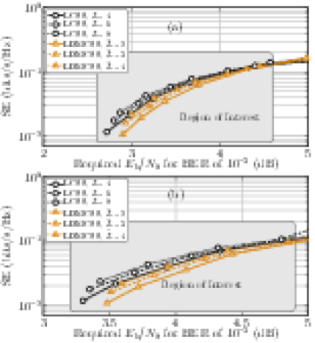
Fig. 7(a) and (b) illustrate the SE versus EE performance of the proposed schemes by modifying L𝐿L or L~~𝐿\tilde{L} and utilizing coherent and non-coherent detection mechanisms, respectively. Interestingly, we observe that with an increase in L𝐿L or L~~𝐿\tilde{L}, the SE increases considerably without imposing a significant penalty on the required Eb/N0subscript𝐸bsubscript𝑁0E_{\mathrm{b}}/N_{0} for the given BER. The increase in needed Eb/N0subscript𝐸bsubscript𝑁0E_{\mathrm{b}}/N_{0} is because more layers affects the sparsity of the un-chirped symbol. Since the un-chirped symbol would be more sparse for lesser number of layer, the required Eb/N0subscript𝐸bsubscript𝑁0E_{\mathrm{b}}/N_{0} would also be less. We also observe another trend, i.e., the achievable SE of LCSS is higher than that of LDMCSS. Moreover, for both LCSS and LDMCSS, the interference for low M𝑀M is higher. Therefore, the EE of both schemes is better for higher values of M𝑀M. Thus, we define a region of interest in which the interference is lower. This region of interest includes Ξ»=⟦8,12βŸ§πœ†812\lambda=\llbracket 8,12\rrbracket; however, it shrinks with an increase in L𝐿L or L~~𝐿\tilde{L}. Overall, for different layers, the performance of LCSS in terms of both EE and SE is marginally better than that of LDMCSS. We also gather from Fig. 7 that generally the coherent detector performs relatively better than the non-coherent detection in the AWGN channel.

Refer to caption
Figure 8: SE versus EE performance for LCSS (with L=4𝐿4L=4) and LDMCSS (with L~=2~𝐿2\tilde{L}=2) with other state-of-the-art schemes considering coherent (a) and non-coherent (b) detection mechanisms for target BER of 10βˆ’3superscript10310^{-3} in AWGN channel.

Next, we compare the performance of the LCSS and LDMCSS by varying the number of layers with other counterparts. For LCSS, we consider L={4,6,8}𝐿468L=\{4,6,8\}, and for LDMCSS, we consider L~={2,3,4}~𝐿234\tilde{L}=\{2,3,4\}. The result for {L,L~}={4,2}𝐿~𝐿42\{L,\tilde{L}\}=\{4,2\}, {L,L~}={6,3}𝐿~𝐿63\{L,\tilde{L}\}=\{6,3\} and {L,L~}={8,4}𝐿~𝐿84\{L,\tilde{L}\}=\{8,4\} are illustrated in Fig. 8, Fig. 9, and Fig. 10, respectively.

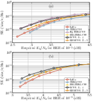
The SE of LCSS is the same as that of IQ-TDM-CSS when L=4𝐿4L=4. Moreover, the SE of DM-TDM-CSS is the same as that of LDMCSS with L=2𝐿2L=2. From Fig. 8 (a) and (b), considering coherent detection, IQ-TDM-CSS performs marginally better than LCSS for low values of Ξ»πœ†\lambda (cf. Fig. 8(a)). On the other hand, the LCSS performs best for non-coherent detection. It is highlighted that IQ-TDM-CSS cannot be detected non-coherently. The performances LCSS is significantly better than TDM-CSS and LoRa for both coherent and non-coherent detections. We also observe that for L~=2~𝐿2\tilde{L}=2, LDMCSS and DM-TDM-CSS have essentially the same signal structure, and so does the SE vs. EE performance considering both coherent and non-coherent detection mechanisms. For coherent detection, LDMCSS also performs better than both TDM-CSS and LoRa; however, for non-coherent detection, the performance of TDM-CSS is also similar to that of LDMCSS and DM-TDM-CSS.

Refer to caption
Figure 9: SE versus EE performance for LCSS (with L=6𝐿6L=6) and LDMCSS (with L~=3~𝐿3\tilde{L}=3) with other state-of-the-art schemes considering coherent (a) and non-coherent (b) detection mechanisms for target BER of 10βˆ’3superscript10310^{-3} in AWGN channel.

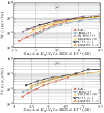
Fig. 9 illustrates that with an increase in L𝐿L and L~~𝐿\tilde{L}, the SE increases significantly, and so does the EE. We observe that now, for L=6𝐿6L=6, the performance of LCSS is markedly better than other counterparts for both the coherent and non-coherent detection (cf. Fig. 9(a) and (b)). On the other hand, considering coherent detection and L~=3~𝐿3\tilde{L}=3, we follow that LDMCSS performs better than DM-CSS, TDM-CSS, and LoRa; however, its performance is marginally worse than IQ-TDM-CSS. For non-coherent detection, LDMCSS performs better than all the other counterparts.

Refer to caption
Figure 10: SE versus EE performance for LCSS (with L=8𝐿8L=8) and LDMCSS (with L~=4~𝐿4\tilde{L}=4) with other state-of-the-art schemes considering coherent (a) and non-coherent (b) detection mechanisms for target BER of 10βˆ’3superscript10310^{-3} in AWGN channel.

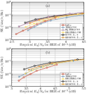
Fig 10 illustrates the SE vs. EE performance considering L=8𝐿8L=8 for LCSS and L~=4~𝐿4\tilde{L}=4 for LDMCSS. We observe that for both coherent and non-coherent detection, the performance of LCSS in terms of achievable SE and EE is superior to the other schemes. LDMCSS, on the other hand, performs marginally worse than LCSS for non-coherent detection, whereas, for coherent detection, IQ-TDM-CSS is marginally better than LDMCSS. It is reiterated that, unlike LDMCSS, IQ-TDM-CSS has some limitations, such as no possibility of non-coherent detection and high sensitivity to the phase and frequency offsets. The latter feature shall become evident in the sequel of the article.

VI-C BER Performance in AWGN Channel

This section compares the BER performance of LCSS and LDMCSS for L={4,6,8}𝐿468L=\{4,6,8\}, and L~={2,3,6}~𝐿236\tilde{L}=\{2,3,6\}. The results are then compared to other methods assuming M=1024𝑀1024M=1024. Note that when L=4𝐿4L=4, LCSS has a SE of 0.39060.39060.3906 bits/s/Hz. For L=6𝐿6L=6, the SE is 0.058590.058590.05859 bits/s/Hz, and L=8𝐿8L=8 results in an SE of 0.078130.078130.07813 bits/s/Hz. For LDMCSS, L~={2,3,4}~𝐿234\tilde{L}=\{2,3,4\} has SEs of 0.035160.035160.03516 bits/s/Hz, 0.052730.052730.05273 bits/s/Hz, and 0.070310.070310.07031 bits/s/Hz.

Refer to caption
Figure 11: BER performance comparison of LCSS and LDMCSS considering coherent (a) and non-coherent (b) detection mechanisms in AWGN channel for M=1024𝑀1024M=1024.

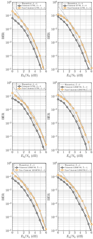
Fig. 11 compares the BER performance of LCSS and LDMCSS for different numbers of layers under both coherent and non-coherent detection. The numerical simulation results are compared with the closed-form BER expressions for the proposed schemes obtained for non-coherent detection. Moreover, for coherent detection, we provide the theoretical upper-bound on the BER for both schemes. It can be observed from Fig. 11, that the numerical results for the non-coherent detection match the theoretical results, whereas, for coherent detection the upper-bound of the BER expressions is tight when compared with the numerical simulations. It also demonstrates that LCSS have a slightly better performance. As the number of layers increases, the SE increases but the BER also increases slightly. For instance, when L𝐿L increases from 444 to 666 for LCSS, the SE increases by 50%percent5050\%, while the Eb/N0subscript𝐸bsubscript𝑁0E_{\mathrm{b}}/N_{0} required for a BER of 10βˆ’3superscript10310^{-3} increases by less than 0.40.40.4 dB for both coherent and non-coherent detection. Similar trends are seen for LDMCSS for both coherent and non-coherent detection mechanisms.

Refer to caption
Figure 12: BER performance comparison of LCSS (with L=8𝐿8L=8) and LDMCSS (with L~=4~𝐿4\tilde{L}=4) with other state-of-the-art schemes considering coherent (a) and non-coherent (b) detection mechanisms in AWGN channel.

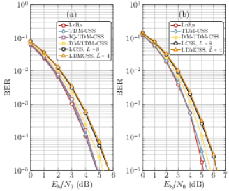
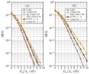
Fig. 12 compares the BER performance of LCSS and LDMCSS with TDM-CSS, DM-TDM-CSS, IQ-TDM-CSS, and LoRa, using M=1024𝑀1024M=1024. Fig. 12(a) shows the BER performance under coherent detection, and Fig. 12(b) illustrates the BER performance under non-coherent detection. For the given M𝑀M, the SE of TDM-CSS, DM-TDM-CSS, IQ-TDM-CSS, and LoRa is 0.019530.019530.01953 bits/s/Hz, 0.035160.035160.03516 bits/s/Hz, 0.039060.039060.03906 bits/s/Hz, and 0.00970.00970.0097 bits/s/Hz respectively. In the comparison, LCSS with L=8𝐿8L=8 and LDMCSS with L~=4~𝐿4\tilde{L}=4 are considered, which results in SE of 0.07810.07810.0781 bits/s/Hz and 0.07030.07030.0703 bits/s/Hz, respectively.

Figs. 12(a) and (b) show that LoRa and TDM-CSS have the best BER performance under coherent detection. IQ-TDM-CSS has slightly worse performance compared to LoRa and TDM-CSS. LCSS and LDMCSS have similar BER performance, which is higher than the other methods; however, it is worth noting that LCSS is 222 times more spectrally efficient than IQ-TDM-CSS, 2.222.222.22 times more than DM-TDM-CSS, 444 times more than TDM-CSS, and 888 times more than LoRa. Similarly, LDMCSS provides 1.81.81.8 times, 222 times, 3.63.63.6 times, and 7.27.27.2 times more SE than IQ-TDM-CSS, TDM-CSS, DM-TDM-CSS, and LoRa, respectively. Therefore, considering the improvement in SE, the increase in BER is only minimal. For example, to achieve the same BER under coherent detection, LCSS and LDMCSS require 0.50.50.5 dB, 0.70.70.7 dB, 0.40.40.4 dB, and 0.80.80.8 dB higher Eb/N0subscript𝐸bsubscript𝑁0E_{\mathrm{b}}/N_{0} than IQ-TDM-CSS, TDM-CSS, DM-TDM-CSS, and LoRa, respectively. Under non-coherent detection, LCSS needs 0.40.40.4 dB, 0.20.20.2 dB, and 0.40.40.4 dB higher Eb/N0subscript𝐸bsubscript𝑁0E_{\mathrm{b}}/N_{0} than TDM-CSS, DM-TDM-CSS, and LoRa, respectively. In contrast, non-coherent LDMCSS needs 0.420.420.42 dB, 0.220.220.22 dB, and 0.420.420.42 dB higher Eb/N0subscript𝐸bsubscript𝑁0E_{\mathrm{b}}/N_{0} than TDM-CSS, DM-TDM-CSS, and LoRa. Therefore, even though LCSS and LDMCSS have slightly higher BER than other methods, the difference is relatively small, considering the improvements in SE they provide.

VI-D BER Performance in Fading Channel

This section examines the performance of LCSS and LDMCSS over a frequency-selective 222-tap fading channel with impulse response of h​(n)=1βˆ’Οβ€‹Ξ΄β€‹(n​T)+ρ​δ​(n​Tβˆ’T)β„Žπ‘›1πœŒπ›Ώπ‘›π‘‡πœŒπ›Ώπ‘›π‘‡π‘‡h(n)=\sqrt{1-\rho}\delta(nT)+\sqrt{\rho}\delta(nT-T), where T𝑇T is the sampling duration, and 0≀ρ≀10𝜌10\leq\rho\leq 1. The results are presented in Fig. 13 for both coherent and non-coherent detection with a specific value of ρ=0.2𝜌0.2\rho=0.2.

Refer to caption
Figure 13: BER performance comparison of LCSS (with L=8𝐿8L=8) and LDMCSS (with L~=4~𝐿4\tilde{L}=4) with other state-of-the-art schemes considering coherent (a) and non-coherent (b) detection mechanisms in a frequency-selective fading channel.

When analyzing the BER performance of LCSS and LDMCSS under coherent detection, as shown in Fig. 13(a), we can see that LCSS performs better than IQ-TDM-CSS and LDMCSS. Additionally, the BER performance of LCSS indicates only a slight degradation compared to DM-TDM-CSS. LoRa has the best BER performance among all the methods. It is also notable that LDMCSS has the worst BER performance, primarily due to the signal structure, making it more susceptible to the frequency selective fading effects.

When analyzing the BER performance of LCSS and LDMCSS under non-coherent detection, as shown in Fig. 13(b), it can be seen that there is a slight increase in the BER of LCSS compared to DM-TDM-CSS. Moreover, the difference in the BER performance between LCSS and LDMCSS is now more noticeable.

Although LCSS and LDMCSS may not have the best BER performance, their higher SE and only slight deterioration make them noteworthy.

VI-E BER Performance considering Frequency Offset

In this section, we examine the effect of carrier frequency offset (FO) on BER performance. The FO causes a linear accumulation of phase rotations from one symbol to another. The equation represents the received symbol, including the FO impact is:

y​(n)=exp⁑{j​2​π​Δ​f​nM}​s​(n)+w​(n),𝑦𝑛𝑗2πœ‹Ξ”π‘“π‘›π‘€π‘ π‘›π‘€π‘›y(n)=\exp\left\{\frac{j2\pi\Delta fn}{M}\right\}s(n)+w(n), (43)

where Δ​fΔ𝑓\Delta f is the FO normalized to the frequency spacing and could be seen as residual FO because IoT modems, like Bluetooth usually have a carrier frequency offset compensator before demodulation; therefore, after compensation, Δ​fΔ𝑓\Delta f reflects the residual FO. To evaluate BER performance, we consider Δ​fΔ𝑓\Delta f of 0.20.20.2 and M=1024𝑀1024M=1024, and AWGN channel. Moreover, we employ both the coherent and non-coherent detection mechanisms.

Refer to caption
Figure 14: BER performance comparison of LCSS (with L=8𝐿8L=8) and LDMCSS (with L~=4~𝐿4\tilde{L}=4) with other state-of-the-art schemes considering coherent (a) and non-coherent (b) detection mechanisms with a FO of Δ​f=0.2Δ𝑓0.2\Delta f=0.2 Hz.

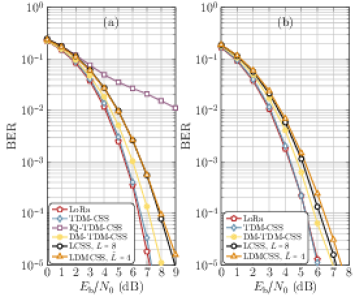
Fig. 14 shows the BER performance in the presence of FO for both coherent detection (Fig. 14(a)) and non-coherent detection (Fig. 14(b)). It can be seen that LCSS and LDMCSS have similar performance when using coherent detection. IQ-TDM-CSS has the worst performance due to its sensitivity to FO. The other schemes, such as LoRa and TDM-CSS have the best performance. Similarly, DM-TDM-CSS shows a slight improvement over LCSS and LDMCSS. For non-coherent detection, LoRa and TDM-CSS have similar performance. However, non-coherently detected LCSS performs better than non-coherently detected LDMCSS. The performance of DM-TDM-CSS falls between that of LCSS and LoRa/TDM-CSS. Another discernible trend is that the non-coherent detector performs relatively better than the coherent detector in the presence of frequency offsets.

VI-F BER Performance considering Phase Offset

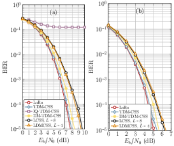
This section examines the performance of all the schemes in the presence of phase offset (PO) commonly found in low-cost devices. The received symbol corrupted by AWGN in the presence of PO is represented by the equation:

y​(n)=exp⁑{jβ€‹Οˆ}​s​(n)+w​(n),π‘¦π‘›π‘—πœ“π‘ π‘›π‘€π‘›y(n)=\exp\{j\psi\}s(n)+w(n), (44)

where Οˆπœ“\psi is the PO. We evaluate the performance of the considered schemes under both coherent and non-coherent detection, using a PO of ψ=Ο€/4πœ“πœ‹4\psi=\nicefrac{{\pi}}{{4}} radians and M=1024𝑀1024M=1024.

The BER performance of proposed schemes in the presence of POs is compared in Fig. 15(a) and (b) using both coherent and non-coherent detection, respectively. It is important to note that IQ-TDM-CSS is highly sensitive to POs as it carries information in both in-phase and quadrature components that drastically affect the integrity of the symbols. The results show that non-coherent detection performs better than coherent detection when POs are present. In coherent detection, LDMCSS performs slightly better than LCSS, requiring 0.10.10.1 dB less Eb/N0subscript𝐸bsubscript𝑁0E_{\mathrm{b}}/N_{0} to reach a BER of 10βˆ’3superscript10310^{-3}. However, this is reversed when using coherent detection, where LCSS requires 0.10.10.1 dB less Eb/N0subscript𝐸bsubscript𝑁0E_{\mathrm{b}}/N_{0} than LDMCSS. For coherent detection, LCSS needs 1.31.31.3 dB, 1.151.151.15 dB, and 0.80.80.8 dB higher Eb/N0subscript𝐸bsubscript𝑁0E_{\mathrm{b}}/N_{0} than LoRa, TDM-CSS, and DM-TDM-CSS, respectively, to reach a BER of 10βˆ’β€‹3superscript10310^{-}3. Meanwhile, LDMCSS requires 1.21.21.2 dB, 1.051.051.05 dB, and 0.70.70.7 dB higher Eb/N0subscript𝐸bsubscript𝑁0E_{\mathrm{b}}/N_{0} than LoRa, TDM-CSS, and DM-TDM-CSS, respectively, for the same target BER. When using non-coherent detection, LCSS requires 0.70.70.7 dB, 0.60.60.6 dB, and 0.30.30.3 dB higher Eb/N0subscript𝐸bsubscript𝑁0E_{\mathrm{b}}/N_{0} than LoRa, TDM-CSS, and DM-TDM-CSS, respectively, indicating that LCSS performs better than other schemes when non-coherent detection is used. Similarly, for non-coherent detection, LDMCSS requires 0.10.10.1 dB higher Eb/N0subscript𝐸bsubscript𝑁0E_{\mathrm{b}}/N_{0} than LCSS over other methods.

Refer to caption
Figure 15: BER performance comparison of LCSS (with L=8𝐿8L=8) and LDMCSS (with L~=4~𝐿4\tilde{L}=4) with other state-of-the-art schemes considering coherent (a) and non-coherent (b) detection mechanisms with a PO of ψ=Ο€/4πœ“πœ‹4\psi=\nicefrac{{\pi}}{{4}} radians.
Refer to caption
Figure 16: PAPR CCDFs for different schemes analyzed in this work. The CCDF curves are obtained for Ξ»=8πœ†8\lambda=8.

VI-G Merits and Limitations of Proposed Schemes

In this section, we first indicate some improvements that the proposed schemes offer relative to other counterparts. Then, we also list some of the limitations of the proposed LCSS and LDMCSS schemes. Some noticeable improvements of LCSS and LDMCSS are:

  1. 1.

    The proposed schemes offer significant improvements in flexibility and a wide range of spectral efficiencies compared to other counterparts. The proposed schemes offer an additional degrees of freedom through the number of layers, which enables a wider range of achievable SEs. In contrast, most state-of-the-art schemes are limited to a lower SE, which can be tuned only through M𝑀M.

  2. 2.

    The proposed schemes offer a higher SE than classical schemes.

  3. 3.

    The proposed schemes offer the flexibility of utilizing both coherent and non-coherent detection mechanisms, which is more suitable for low-cost devices commonly used in LPWANs. While some traditional schemes can also use both detection mechanisms, they do not offer the same level of SE as the proposed schemes, or they cannot use either of the detection mechanisms altogether. The ability to use non-coherent detection can be a key advantage for cost-effective devices with power constraints.

  4. 4.

    The proposed schemes have a broad range of applicability due to their adaptability to various types of communication. Their flexibility in terms of system efficiency allows them to be tailored to specific applications, considering factors such as data rate, range, and interference environment, making them more suitable than traditional methods.

On the other hand, some discernible limitations of the proposed schemes are:

  1. 1.

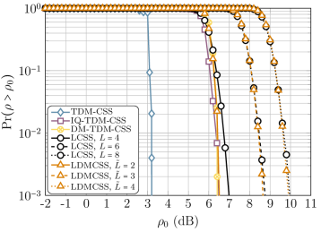
    The proposed schemes do not have a constant envelope, which can present challenges during their practical implementation. This would increase the peak-to-average power ratio (PAPR), making it susceptible to non-linear distortions in the system. However, it is worth noting that many other CSS schemes capable of achieving higher SE than the classical LoRa, also do not have a constant envelope. This is because these schemes either use PSs or additional FSs to attain higher SE. PAPR, ρ𝜌\rho is mathematically defined as:

    ρ=max⁑{|s​(n)|2}1Mβ€‹βˆ‘n=0Mβˆ’1|s​(n)|2.𝜌superscript𝑠𝑛21𝑀superscriptsubscript𝑛0𝑀1superscript𝑠𝑛2\rho=\frac{\max\left\{|s(n)|^{2}\right\}}{\frac{1}{M}\sum_{n=0}^{M-1}|s(n)|^{2}}. (45)

    To graphically illustrate PAPR, the complementary cumulative distribution function (CCDF) is used, which measures the probability that ρ𝜌\rho exceeds a specified threshold, ρ0subscript𝜌0\rho_{0}, i.e., Pr​(ρ>ρ0)Pr𝜌subscript𝜌0\mathrm{Pr}(\rho>\rho_{0}). Fig. 16 depicts the CCDFs for PAPR of various schemes considered in this study, all evaluated for Ξ»=8πœ†8\lambda=8. For LCSS, we consider L𝐿L equal to 4,6464,6 and 888, whereas for LDMCSS, we consider L~=2,3~𝐿23\tilde{L}=2,3 and 444. It can be observed that with an increase in the number of layers for both LCSS and LDMCSS, the PAPR also increases. However, we also notice that the other counterparts, which activate multiple FS, also have significantly higher PAPR. The results in Fig. 16 indicate that a trade-off is necessary regarding how many layers should be used, as the higher the number of layers, the higher will be the non-linear distortions. However, based on the component’s non-linear characteristics, the number of layers for the proposed schemes can be tuned to avoid these non-linear distortions. This flexibility is not possible with other existing schemes in the literature.

    The transceiver, especially the receiver for the proposed schemes, is more complex than other CSS-based counterparts, requiring more arithmetic operations to demodulate the signal. It can be noticed that the number of necessary DFTs to retrieve information from the received symbols is equal to L𝐿L and L~~𝐿\tilde{L} for LCSS and LDMCSS, respectively. Thus, increasing the number of layers would also increase the receiver complexity. On the other hand, DM-TDM-CSS, IQ-TDM-CSS, and TDM-CSS require the computation of two DFTs to demodulate the received symbol. However, it is important to notice that the increase in complexity is not significant compared to the improvement in the spectral and energy efficiency, e.g., LCSS with L=6𝐿6L=6 and LDMCSS with L~=3~𝐿3\tilde{L}=3 exhibit a spectral efficiency that is six times that of classical LoRa. However, LCSS requires five additional computations of DFTs, and LDMCSS requires two additional computations of DFTs. Thus, it is apparent that the proposed schemes reduce over-the-air transmission time compared to the classical counterparts. Assuming DFT is implemented via fast Fourier transform (FFT), the arithmetic operations needed for the studied schemes are summarized in Table II. This increase in receiver complexity would have minimal impact on the longevity of the battery-powered terminals, as it primarily depends on the transmit power. Since we have comprehensively established that the proposed schemes are more power efficient than other counterparts, we believe that the transmit power required would be significantly less, improving the longevity of the battery-powered devices in LPWANs. On the other hand, as far as an increase in power consumption related to an increase in receiver complexity is concerned, that would be minimal because the power consumption of computing additional FFT would be significantly less. Moreover, employing the proposed schemes, the battery-powered terminals would have to transmit less frequently, minimizing power consumption.

    TABLE II: Receiver complexities of different CSS schemes.
    CSS Scheme Arithmetic Operations
    LoRa 4​M​log2⁑(M)βˆ’6​M+84𝑀subscript2𝑀6𝑀84M\log_{2}(M)-6M+8
    TDM-CSS 8​M​log2⁑(M)βˆ’12​M+168𝑀subscript2𝑀12𝑀168M\log_{2}(M)-12M+16
    IQ-TDM-CSS 8​M​log2⁑(M)βˆ’12​M+168𝑀subscript2𝑀12𝑀168M\log_{2}(M)-12M+16
    DM-TDM-CSS 8​M​log2⁑(M)βˆ’12​M+168𝑀subscript2𝑀12𝑀168M\log_{2}(M)-12M+16
    LCSS 4​L​M​log2⁑(M)βˆ’6​L​M+8​L4𝐿𝑀subscript2𝑀6𝐿𝑀8𝐿4LM\log_{2}(M)-6LM+8L
    LDMCSS 4​L~​M​log2⁑(M)βˆ’6​L~​M+8​L~4~𝐿𝑀subscript2𝑀6~𝐿𝑀8~𝐿4\tilde{L}M\log_{2}(M)-6\tilde{L}M+8\tilde{L}
  2. 2.

    As L𝐿L increases, then so does the complexity and interference level of the LCSS and LDMCSS schemes. Because of this increase in interference, the energy efficiency starts to decrease, reducing the region of interest in SE for the proposed schemes.

VI-H Selecting Number of Layers

Selecting the number of layers for the proposed LCSS and LDMCSS is a critical aspect. On the one hand, increasing the number of layers increases the SE and EE; however, on the other hand, it also increases interference power, complexity, and PAPR. The improvement in SE and EE increases the transmission distances, and more information can be transmitted; therefore, the transmitter has to communicate less frequently, reducing power consumption. However, this also restricts using higher SF because of the increase in interference power for lower M𝑀M (i.e., lower SF). Moreover, the non-linear distortion may also increase due to higher PAPR. Selecting the number of layers depends primarily on the application requirements and the characteristics of the equipment in use. If the components have a narrow linear range, using less number of layers may be preferable to avoid non-linear distortions. Also, fewer layers can be used if lower data rates are needed at shorter distances. Considering all these characteristics, we believe using L={6,8}𝐿68L=\{6,8\} and L~={3,4}~𝐿34\tilde{L}=\{3,4\} could provide a good compromise between an increase in SE, improvement in EE, and the impact of an increase in interference power and non-linear distortions. Using these much number of layers improves the SE and EE significantly while not proving so harsh on the interference power and non-linear distortions.

VII Conclusions

The article introduces two novel waveform designs, LCSS and LDMCSS, as alternatives to the LPWAN technology, LoRa. These designs proffer greater adaptability in adjusting data rates for various applications and conditions and possess high achievable SE and EE compared to the current state-of-the-art options. Despite their similarities, LCSS and LDMCSS differ in the intricacies of their waveform design, with LDMCSS necessitating fewer layers, thus rendering it less complex. However, it must be noted that the layered structure of these designs can lead to interference among layers, particularly when lower alphabet cardinalities and more layers are involved. Despite certain limitations, such as the high receiver complexity, interference due to the layered structure, and the PAPR, the proposed schemes have exhibited a higher SE than other LPWAN alternatives. Furthermore, these schemes can employ both coherent and non-coherent detection mechanisms and are relatively robust against frequency and phase offsets that may occur in low-cost devices. While LCSS demonstrates slightly better performance than LDMCSS, it is computationally complex. We hope that these new CSS-based designs, presented herein, inspire further research aimed at enhancing their performance.

References

  • [1] LoRaWAN 1.1 Specification. Technical report, LoRa Alliance Tech. Committee, Fremont, CA, USA, 2017.
  • [2] LoRa modulation basics an1200.22. Technical report, Semtech Corporat., Camarillo, CA, USA, 2015.
  • [3] L.Β Vangelista. Frequency shift chirp modulation: The LoRa modulation. IEEE Sig. Process. Lett., 24(12):1818–1821, 2017.
  • [4] M.Β Chiani and A.Β Elzanaty. On the lora modulation for iot: Waveform properties and spectral analysis. IEEE Internet of Things Journal, 6(5):8463–8470, 2019.
  • [5] T.Β Elshabrawy and J.Β Robert. Interleaved chirp spreading lora-based modulation. IEEE Internet Things J., 6(2):3855–3863, 2019.
  • [6] T.Β Elshabrawy, P.Β Edward, M.Β Ashour, and J.Β Robert. On the different mathematical realizations for the digital synthesis of lora-based modulation. In 25th European Wireless Conference, pages 1–6. VDE, 2019.
  • [7] R.Β Bomfin, M.Β Chafii, and G.Β Fettweis. A novel modulation for IoT: PSK-LoRa. In IEEE Veh. Technol. Conf., pages 1–5. IEEE, 2019.
  • [8] L.Β Vangelista and A.Β Cattapan. A new LoRa-compatible modulation improving the LoRaWAN network level performance. In IEEE Latin-American Conf. Commun., pages 1–6, 2019.
  • [9] M.Β Hanif and H.Β H. Nguyen. Slope-Shift Keying LoRa-Based Modulation. IEEE Internet Things J., 8(1):211–221, 2020.
  • [10] I.Β B.Β F. deΒ Almeida, M.Β Chafii, A.Β Nimr, and G.Β Fettweis. In-phase and quadrature chirp spread spectrum for IoT communications. In IEEE Global Commun. Conf., pages 1–6. IEEE, 2020.
  • [11] I.Β B.Β F. deΒ Almeida, M.Β Chafii, A.Β Nimr, and G.Β Fettweis. Alternative chirp spread spectrum techniques for LPWANs. IEEE Trans. Green Commun. Netw., pages 1–1, 2021.
  • [12] M.Β Hanif and H.Β H. Nguyen. Frequency-shift chirp spread spectrum communications with index modulation. IEEE Internet Things J., 2021.
  • [13] G.Β Baruffa and L.Β Rugini. Performance of LoRa-based schemes and quadrature chirp index modulation. IEEE Internet Things J., 2021.
  • [14] A.Β Mondal, M.Β Hanif, and H.Β H. Nguyen. SSK-ICS LoRa: A LoRa-based modulation scheme with constant envelope and enhanced data rate. IEEE Commun. Lett., pages 1–1, 2022.
  • [15] A.Β W. Azim, J.Β L.Β G. Monsalve, and M.Β Chafii. Enhanced PSK-LoRa. IEEE Wire. Commun. Lett., 11(3):612–616, 2022.
  • [16] Q.Β Yu, H.Β Wang, Z.Β Lu, and S.Β An. Group-Based CSS Modulation: a novel enhancement to lora physical layer. IEEE Wire. Commun. Lett., 11(3):660–664, 2022.
  • [17] S.Β An, H.Β Wang, Y.Β Sun, Z.Β Lu, and Q.Β Yu. Time domain multiplexed lora modulation waveform design for IoT communication. IEEE Commun. Lett., 2022.
  • [18] W.Β Azim, A, A.Β Bazzi, R.Β Shubair, and M.Β Chafii. Dual-mode chirp spread spectrum modulation. IEEE Wireless Commun. Lett., pages 1–1, 2022.
  • [19] A.Β W. Azim, A.Β Bazzi, M.Β Fatima, R.Β Shubair, and M.Β Chafii. Dual-mode time domain multiplexed chirp spread spectrum. IEEE Transactions on Vehicular Technology, 2023.
  • [20] W.Β Azim, A, A.Β Bazzi, R.Β Shubair, and M.Β Chafii. Chirp spread spectrum-based waveform design and detection mechanisms for LPWAN-based IoT – a survey. arXiv preprint arXiv:2208.10274, 2022.
  • [21] T.Β Elshabrawy and J.Β Robert. Closed-form approximation of LoRa modulation BER performance. IEEE Commun. Lett., 22(9):1778–1781, 2018.
  • [22] F.Β Xiong. Digital modulation techniques. London, 2006.

Appendix A Orthogonality and Interference Analysis of Benchmark Schemes

It is highlighted that, like the proposed schemes, the benchmark schemes considered in this work, TDM-CSS, IQ-TDM-CSS, and DM-TDM-CSS, are also not orthogonal and result in interference due to time-domain multiplexing. This appendix briefly provides the orthogonality and interference analysis results for these benchmark schemes.

A-A TDM-CSS

The transmit symbol for TDM-CSS is given as:

s​(n)=exp⁑{j​πM​(2​k1​n+n2)}+exp⁑{j​πM​(2​k2​nβˆ’n2)}.π‘ π‘›π‘—πœ‹π‘€2subscriptπ‘˜1𝑛superscript𝑛2π‘—πœ‹π‘€2subscriptπ‘˜2𝑛superscript𝑛2\begin{split}s(n)=\exp\left\{j\frac{\pi}{M}\left(2k_{1}n+n^{2}\right)\right\}+\exp\left\{j\frac{\pi}{M}\left(2k_{2}n-n^{2}\right)\right\}.\end{split} (46)

To evaluate the orthogonality of TDM-CSS symbols, we consider the inner product of 𝒔𝒔\boldsymbol{s} and 𝒔¯¯𝒔\overline{\boldsymbol{s}}, i.e., βŸ¨π’”,π’”Β―βŸ©π’”Β―π’”\langle\boldsymbol{s},\overline{\boldsymbol{s}}\rangle where the activated FSs are kΒ―1subscriptΒ―π‘˜1\overline{k}_{1} and kΒ―2subscriptΒ―π‘˜2\overline{k}_{2}. Assuming that k1β‰ kΒ―1subscriptπ‘˜1subscriptΒ―π‘˜1k_{1}\neq\overline{k}_{1} and k2β‰ kΒ―2subscriptπ‘˜2subscriptΒ―π‘˜2k_{2}\neq\overline{k}_{2}, βŸ¨π’”,π’”Β―βŸ©π’”Β―π’”\langle\boldsymbol{s},\overline{\boldsymbol{s}}\rangle yields:

βŸ¨π’”,π’”Β―βŸ©=α​exp⁑{βˆ’j​π2​M​(k1βˆ’kΒ―2)2}+Ξ±βˆ—β€‹exp⁑{j​π2​M​(k2βˆ’kΒ―1)2},π’”Β―π’”π›Όπ‘—πœ‹2𝑀superscriptsubscriptπ‘˜1subscriptΒ―π‘˜22superscriptπ›Όβˆ—π‘—πœ‹2𝑀superscriptsubscriptπ‘˜2subscriptΒ―π‘˜12\begin{split}\langle\boldsymbol{s},\overline{\boldsymbol{s}}\rangle&=\alpha\exp\left\{-j\frac{\pi}{2M}\left(k_{1}-\overline{k}_{2}\right)^{2}\right\}\\ &~{}+\alpha^{\ast}\exp\left\{j\frac{\pi}{2M}\left(k_{2}-\overline{k}_{1}\right)^{2}\right\},\end{split} (47)

where Ξ±=M/2​exp⁑{j​π/4}𝛼𝑀2π‘—πœ‹4\alpha=\sqrt{\nicefrac{{M}}{{2}}}\exp\left\{j\nicefrac{{\pi}}{{4}}\right\}. It can be observed that TDM-CSS symbols are not orthogonal because as activated FSs of the two multiplexed symbols results interference.

As TDM-CSS multiplexes symbols with two different chirp rates; therefore, the received symbol, r​(n)π‘Ÿπ‘›r(n), is de-chirped by the down-chirp, cd​(n)=exp⁑{βˆ’j​πM​n2}subscript𝑐dπ‘›π‘—πœ‹π‘€superscript𝑛2c_{\mathrm{d}}(n)=\exp\left\{-j\frac{\pi}{M}n^{2}\right\}, and the up-chirp, cu​(n)=cuβˆ—β€‹(n)subscript𝑐u𝑛subscriptsuperscriptπ‘βˆ—u𝑛c_{\mathrm{u}}(n)=c^{\ast}_{\mathrm{u}}(n), resulting in r1​(n)=r​(n)​cd​(n)subscriptπ‘Ÿ1π‘›π‘Ÿπ‘›subscript𝑐d𝑛r_{1}(n)=r(n)c_{\mathrm{d}}(n) and r2​(n)=r​(n)​cu​(n)subscriptπ‘Ÿ2π‘›π‘Ÿπ‘›subscript𝑐u𝑛r_{2}(n)=r(n)c_{\mathrm{u}}(n), respectively. Considering that k~1=k1βˆ’ksubscript~π‘˜1subscriptπ‘˜1π‘˜\tilde{k}_{1}=k_{1}-k and k~2=k2βˆ’ksubscript~π‘˜2subscriptπ‘˜2π‘˜\tilde{k}_{2}=k_{2}-k, then the M𝑀M-order DFT of these de-chirped symbols, R1​(k)subscript𝑅1π‘˜R_{1}(k) and R2​(k)subscript𝑅2π‘˜R_{2}(k), are given as:

R1​(k)=M⏟Signal+Ξ±βˆ—β€‹exp⁑{j​π2​M​k~22}​β1⏟Interference+W1​(k)⏟Noise,subscript𝑅1π‘˜subscriptβŸπ‘€Signalsubscript⏟superscriptπ›Όβˆ—π‘—πœ‹2𝑀superscriptsubscript~π‘˜22subscript𝛽1Interferencesubscript⏟subscriptπ‘Š1π‘˜NoiseR_{1}(k)=\underbrace{M}_{\text{Signal}}+\underbrace{\alpha^{\ast}\exp\left\{j\frac{\pi}{2M}\tilde{k}_{2}^{2}\right\}\beta_{1}}_{\text{Interference}}+\underbrace{W_{1}(k)}_{\text{Noise}}, (48)

and

R2​(k)=M⏟Signal+α​exp⁑{βˆ’j​π2​M​k~12}​β2⏟Interference+W2​(k)⏟Noise,subscript𝑅2π‘˜subscriptβŸπ‘€SignalsubscriptβŸπ›Όπ‘—πœ‹2𝑀superscriptsubscript~π‘˜12subscript𝛽2Interferencesubscript⏟subscriptπ‘Š2π‘˜NoiseR_{2}(k)=\underbrace{M}_{\text{Signal}}+\underbrace{\alpha\exp\left\{-j\frac{\pi}{2M}\tilde{k}_{1}^{2}\right\}\beta_{2}}_{\text{Interference}}+\underbrace{W_{2}(k)}_{\text{Noise}}, (49)

respectively, where

Ξ²1=1+exp⁑{j​π2​(M+2​k~2)}={1rem​(|k~2|,2)=0βˆ’1rem​(|k~2|,2)=1,Ξ²2=1+exp⁑{βˆ’j​π2​(M+2​k~1)}={1rem​(|k~1|,2)=0βˆ’1rem​(|k~1|,2)=1.formulae-sequencesubscript𝛽11π‘—πœ‹2𝑀2subscript~π‘˜2cases1remsubscript~π‘˜2201remsubscript~π‘˜221subscript𝛽21π‘—πœ‹2𝑀2subscript~π‘˜1cases1remsubscript~π‘˜1201remsubscript~π‘˜121\begin{split}\beta_{1}&=1+\exp\left\{j\frac{\pi}{2}\left(M+2\tilde{k}_{2}\right)\right\}\\ &=\begin{dcases}1&\quad\mathrm{rem}\left(|\tilde{k}_{2}|,2\right)=0\\ -1&\quad\mathrm{rem}\left(|\tilde{k}_{2}|,2\right)=1\\ \end{dcases},\\ \beta_{2}&=1+\exp\left\{-j\frac{\pi}{2}\left(M+2\tilde{k}_{1}\right)\right\}\\ &=\begin{dcases}1&\quad\mathrm{rem}\left(|\tilde{k}_{1}|,2\right)=0\\ -1&\quad\mathrm{rem}\left(|\tilde{k}_{1}|,2\right)=1\\ \end{dcases}.\end{split} (50)

Moreover, W1​(k)subscriptπ‘Š1π‘˜W_{1}(k) and W2​(k)subscriptπ‘Š2π‘˜W_{2}(k) are the DFT outputs for w1​(n)=w​(n)​cd​(n)subscript𝑀1𝑛𝑀𝑛subscript𝑐d𝑛w_{1}(n)=w(n)c_{\mathrm{d}}(n) and w2​(n)=w​(n)​cu​(n)subscript𝑀2𝑛𝑀𝑛subscript𝑐u𝑛w_{2}(n)=w(n)c_{\mathrm{u}}(n), respectively. From (48) and (49), we gather that the activated FS of the two multiplexed symbols causes interference with each other.

A-B IQ-TDM-CSS

The transmit symbol for IQ-TDM-CSS is given as:

s​(n)=exp⁑{j​πM​(2​ki​n+n2)}+j​exp⁑{j​πM​(2​kq​n+n2)}+exp⁑{j​πM​(2​k~i​nβˆ’n2)}+j​exp⁑{j​πM​(2​k~q​nβˆ’n2)}.π‘ π‘›π‘—πœ‹π‘€2subscriptπ‘˜π‘–π‘›superscript𝑛2π‘—π‘—πœ‹π‘€2subscriptπ‘˜π‘žπ‘›superscript𝑛2π‘—πœ‹π‘€2subscript~π‘˜π‘–π‘›superscript𝑛2π‘—π‘—πœ‹π‘€2subscript~π‘˜π‘žπ‘›superscript𝑛2\begin{split}s(n)&=\exp\left\{j\frac{\pi}{M}\left(2k_{i}n+n^{2}\right)\right\}+j\exp\left\{j\frac{\pi}{M}\left(2k_{q}n+n^{2}\right)\right\}\\ &+\exp\left\{j\frac{\pi}{M}\left(2\tilde{k}_{i}n-n^{2}\right)\right\}\!+\!j\exp\left\{j\frac{\pi}{M}\left(2\tilde{k}_{q}n-n^{2}\right)\right\}.\end{split} (51)

The inner product of two IQ-TDM-CSS symbols, 𝒔𝒔\boldsymbol{s}, and 𝒔¯¯𝒔\overline{\boldsymbol{s}}, leads to:

βŸ¨π’”,π’”Β―βŸ©=Ξ±(exp{βˆ’jΟ€2​M(kiβˆ’kΒ―~i)2}βˆ’j​exp⁑{βˆ’j​π2​M​(kiβˆ’kΒ―~q)2}+j​exp⁑{βˆ’j​π2​M​(kqβˆ’kΒ―~i)2}+exp{βˆ’jΟ€2​M(kqβˆ’kΒ―~q)2})+Ξ±βˆ—(exp{jΟ€2​M(k~iβˆ’kΒ―i)2}βˆ’j​exp⁑{j​π2​M​(k~iβˆ’kΒ―q)2}+j​exp⁑{j​π2​M​(k~qβˆ’kΒ―i)2}+exp{jΟ€2​M(k~qβˆ’kΒ―q)2}).π’”Β―π’”π›Όπ‘—πœ‹2𝑀superscriptsubscriptπ‘˜π‘–subscript~Β―π‘˜π‘–2π‘—π‘—πœ‹2𝑀superscriptsubscriptπ‘˜π‘–subscript~Β―π‘˜π‘ž2π‘—π‘—πœ‹2𝑀superscriptsubscriptπ‘˜π‘žsubscript~Β―π‘˜π‘–2π‘—πœ‹2𝑀superscriptsubscriptπ‘˜π‘žsubscript~Β―π‘˜π‘ž2superscriptπ›Όβˆ—π‘—πœ‹2𝑀superscriptsubscript~π‘˜π‘–subscriptΒ―π‘˜π‘–2π‘—π‘—πœ‹2𝑀superscriptsubscript~π‘˜π‘–subscriptΒ―π‘˜π‘ž2π‘—π‘—πœ‹2𝑀superscriptsubscript~π‘˜π‘žsubscriptΒ―π‘˜π‘–2π‘—πœ‹2𝑀superscriptsubscript~π‘˜π‘žsubscriptΒ―π‘˜π‘ž2\begin{split}\langle\boldsymbol{s},\overline{\boldsymbol{s}}\rangle&=\alpha\left(\exp\left\{-j\frac{\pi}{2M}\left(k_{i}-\tilde{\overline{k}}_{i}\right)^{2}\right\}\right.\\ &\left.~{}-j\exp\left\{-j\frac{\pi}{2M}\left(k_{i}-\tilde{\overline{k}}_{q}\right)^{2}\right\}\right.\\ &\left.~{}+j\exp\left\{-j\frac{\pi}{2M}\left(k_{q}-\tilde{\overline{k}}_{i}\right)^{2}\right\}\right.\\ &\left.~{}+\exp\left\{-j\frac{\pi}{2M}\left(k_{q}-\tilde{\overline{k}}_{q}\right)^{2}\right\}\right)\\ &~{}+\alpha^{\ast}\left(\exp\left\{j\frac{\pi}{2M}\left(\tilde{k}_{i}-\overline{k}_{i}\right)^{2}\right\}\right.\\ &\left.~{}-j\exp\left\{j\frac{\pi}{2M}\left(\tilde{k}_{i}-\overline{k}_{q}\right)^{2}\right\}\right.\\ &\left.~{}+j\exp\left\{j\frac{\pi}{2M}\left(\tilde{k}_{q}-\overline{k}_{i}\right)^{2}\right\}\right.\\ &\left.~{}+\exp\left\{j\frac{\pi}{2M}\left(\tilde{k}_{q}-\overline{k}_{q}\right)^{2}\right\}\right).\end{split} (52)

To attain (52), we consider that the activated FSs in 𝒔¯¯𝒔\overline{\boldsymbol{s}} are kΒ―isubscriptΒ―π‘˜π‘–\overline{k}_{i}, kΒ―qsubscriptΒ―π‘˜π‘ž\overline{k}_{q}, kΒ―~isubscript~Β―π‘˜π‘–\tilde{\overline{k}}_{i}, and kΒ―~qsubscript~Β―π‘˜π‘ž\tilde{\overline{k}}_{q}. Moreover, it is also assumed that kΒ―~iβ‰ kisubscript~Β―π‘˜π‘–subscriptπ‘˜π‘–\tilde{\overline{k}}_{i}\neq k_{i}, kΒ―qβ‰ kqsubscriptΒ―π‘˜π‘žsubscriptπ‘˜π‘ž\overline{k}_{q}\neq k_{q}, kΒ―~iβ‰ k~isubscript~Β―π‘˜π‘–subscript~π‘˜π‘–\tilde{\overline{k}}_{i}\neq\tilde{k}_{i}, and kΒ―~qβ‰ k~qsubscript~Β―π‘˜π‘žsubscript~π‘˜π‘ž\tilde{\overline{k}}_{q}\neq\tilde{k}_{q}. It is apparent that the IQ-TDM-CSS symbols are not orthogonal because the in-phase activated FS of one IQ-TDM-CSS symbol causes interference within both the in-phase and quadrature components of the other IQ-TDM-CSS symbol. Similarly, the activated FS for the quadrature component of one IQ-TDM-CSS symbol causes interference within both the in-phase and quadrature components of the other IQ-TDM-CSS symbol.

In IQ-TDM-CSS, we again have two multiplexed symbols, both having activated FSs in the in-phase and quadrature components. Like TDM-CSS, the received symbol, r​(n)π‘Ÿπ‘›r(n), would be de-chirped using cd​(n)subscript𝑐d𝑛c_{\mathrm{d}}(n) and cu​(n)subscript𝑐u𝑛c_{\mathrm{u}}(n), as r1​(n)=r​(n)​cd​(n)subscriptπ‘Ÿ1π‘›π‘Ÿπ‘›subscript𝑐d𝑛r_{1}(n)=r(n)c_{\mathrm{d}}(n) and r2​(n)=r​(n)​cu​(n)subscriptπ‘Ÿ2π‘›π‘Ÿπ‘›subscript𝑐u𝑛r_{2}(n)=r(n)c_{\mathrm{u}}(n). Considering that ΞΊi=kiβˆ’ksubscriptπœ…π‘–subscriptπ‘˜π‘–π‘˜\kappa_{i}=k_{i}-k, ΞΊq=kqβˆ’ksubscriptπœ…π‘žsubscriptπ‘˜π‘žπ‘˜\kappa_{q}=k_{q}-k, ΞΊ~i=k~iβˆ’ksubscript~πœ…π‘–subscript~π‘˜π‘–π‘˜\tilde{\kappa}_{i}=\tilde{k}_{i}-k, and ΞΊ~q=k~qβˆ’ksubscript~πœ…π‘žsubscript~π‘˜π‘žπ‘˜\tilde{\kappa}_{q}=\tilde{k}_{q}-k, the DFT of r1​(n)subscriptπ‘Ÿ1𝑛r_{1}(n) and r2​(n)subscriptπ‘Ÿ2𝑛r_{2}(n) results in:

R1​(k)=2​M⏟Signal+Ξ±βˆ—β€‹(exp⁑{j​π2​M​κ~i2}​β1,i+exp⁑{j​π2​M​κ~q2}​β1,q)⏟Interference+W1​(k)⏟Noise,subscript𝑅1π‘˜subscript⏟2𝑀Signalsubscript⏟superscriptπ›Όβˆ—π‘—πœ‹2𝑀superscriptsubscript~πœ…π‘–2subscript𝛽1π‘–π‘—πœ‹2𝑀superscriptsubscript~πœ…π‘ž2subscript𝛽1π‘žInterferencesubscript⏟subscriptπ‘Š1π‘˜Noise\begin{split}R_{1}(k)&=\underbrace{2M}_{\text{Signal}}\\ &~{}+\underbrace{\alpha^{\ast}\left(\exp\left\{j\frac{\pi}{2M}\tilde{\kappa}_{i}^{2}\right\}\beta_{1,i}+\exp\left\{j\frac{\pi}{2M}\tilde{\kappa}_{q}^{2}\right\}\beta_{1,q}\right)}_{\text{Interference}}\\ &+\underbrace{W_{1}(k)}_{\text{Noise}},\end{split} (53)

and

R2​(k)=2​M⏟Signal+α​(exp⁑{βˆ’j​π2​M​κi2}​β2,i+exp⁑{βˆ’j​π2​M​κq2}​β2,q)⏟Interference+W2​(k)⏟Noise,subscript𝑅2π‘˜subscript⏟2𝑀SignalsubscriptβŸπ›Όπ‘—πœ‹2𝑀superscriptsubscriptπœ…π‘–2subscript𝛽2π‘–π‘—πœ‹2𝑀superscriptsubscriptπœ…π‘ž2subscript𝛽2π‘žInterferencesubscript⏟subscriptπ‘Š2π‘˜Noise\begin{split}R_{2}(k)&=\underbrace{2M}_{\text{Signal}}\\ &~{}+\underbrace{\alpha\left(\exp\left\{-j\frac{\pi}{2M}\kappa_{i}^{2}\right\}\beta_{2,i}+\exp\left\{-j\frac{\pi}{2M}\kappa_{q}^{2}\right\}\beta_{2,q}\right)}_{\text{Interference}}\\ &~{}+\underbrace{W_{2}(k)}_{\text{Noise}},\end{split} (54)

respectively, where

Ξ²1,(β‹…)=1+exp⁑{j​π2​(M+2​κ~(β‹…))}subscript𝛽1β‹…1π‘—πœ‹2𝑀2subscript~πœ…β‹…\beta_{1,(\cdot)}=1+\exp\left\{j\frac{\pi}{2}\left(M+2\tilde{\kappa}_{(\cdot)}\right)\right\} (55)

, and

Ξ²2,(β‹…)=1+exp⁑{βˆ’j​π2​(M+2​κ(β‹…))},subscript𝛽2β‹…1π‘—πœ‹2𝑀2subscriptπœ…β‹…\beta_{2,(\cdot)}=1+\exp\left\{-j\frac{\pi}{2}\left(M+2\kappa_{(\cdot)}\right)\right\}, (56)

where (β‹…)β‹…(\cdot) in the subscript is used to denote i𝑖i and qπ‘žq. As aforementioned, in IQ-TDM-CSS, two symbols are multiplexed, where each symbol has an activated in-phase and quadrature FS. The results indicate that one symbol’s activated in-phase and quadrature FS causes interference with the other.

A-C DM-TDM-CSS

he transmit symbol for DM-TDM-CSS is given as:

s​(n)=exp⁑{j​πM​(2​ke,1​n+n2)}+exp⁑{j​πM​(2​ko,1​n+n2)}+exp⁑{j​πM​(2​ke,2​nβˆ’n2)}+exp⁑{j​πM​(2​ko,2​nβˆ’n2)}.π‘ π‘›π‘—πœ‹π‘€2subscriptπ‘˜e1𝑛superscript𝑛2π‘—πœ‹π‘€2subscriptπ‘˜o1𝑛superscript𝑛2π‘—πœ‹π‘€2subscriptπ‘˜e2𝑛superscript𝑛2π‘—πœ‹π‘€2subscriptπ‘˜o2𝑛superscript𝑛2\begin{split}s(n)&=\exp\left\{j\frac{\pi}{M}\left(2k_{\mathrm{e},1}n\!+\!n^{2}\right)\right\}\!+\!\exp\left\{j\frac{\pi}{M}\left(2k_{\mathrm{o},1}n\!+\!n^{2}\right)\right\}\\ &~{}+\exp\left\{j\frac{\pi}{M}\left(2k_{\mathrm{e},2}n\!-\!n^{2}\right)\right\}\!+\!\exp\left\{j\frac{\pi}{M}\left(2k_{\mathrm{o},2}n\!-\!n^{2}\right)\right\}.\end{split} (57)

To evaluate the closed-form expressions for orthogonality between two DM-TDM-CSS symbols, we evaluate the inner product of 𝒔𝒔\boldsymbol{s} and 𝒔¯¯𝒔\overline{\boldsymbol{s}}, which yields:

βŸ¨π’”,π’”Β―βŸ©=Ξ±(exp{βˆ’jΟ€2​M(ke,1βˆ’kΒ―e,2)2}+exp{βˆ’jΟ€2​M(ko,1βˆ’kΒ―o,2)2})+Ξ±βˆ—(exp{jΟ€2​M(ke,2βˆ’kΒ―e,1)2}+exp{jΟ€2​M(ko,2βˆ’kΒ―o,1)2}).π’”Β―π’”π›Όπ‘—πœ‹2𝑀superscriptsubscriptπ‘˜e1subscriptΒ―π‘˜e22π‘—πœ‹2𝑀superscriptsubscriptπ‘˜o1subscriptΒ―π‘˜o22superscriptπ›Όβˆ—π‘—πœ‹2𝑀superscriptsubscriptπ‘˜e2subscriptΒ―π‘˜e12π‘—πœ‹2𝑀superscriptsubscriptπ‘˜o2subscriptΒ―π‘˜o12\begin{split}\langle\boldsymbol{s},\overline{\boldsymbol{s}}\rangle&=\alpha\left(\exp\left\{-j\frac{\pi}{2M}\left(k_{\mathrm{e},1}-\overline{k}_{\mathrm{e},2}\right)^{2}\right\}\right.\\ &\left.~{}+\exp\left\{-j\frac{\pi}{2M}\left(k_{\mathrm{o},1}-\overline{k}_{\mathrm{o},2}\right)^{2}\right\}\right)\\ &~{}+\alpha^{\ast}\left(\exp\left\{j\frac{\pi}{2M}\left(k_{\mathrm{e},2}-\overline{k}_{\mathrm{e},1}\right)^{2}\right\}\right.\\ &\left.~{}+\exp\left\{j\frac{\pi}{2M}\left(k_{\mathrm{o},2}-\overline{k}_{\mathrm{o},1}\right)^{2}\right\}\right).\end{split} (58)

It must be noticed that the activated even and odd FSs in 𝒔¯¯𝒔\overline{\boldsymbol{s}} are kΒ―e,1β‰ ke,1subscriptΒ―π‘˜e1subscriptπ‘˜e1\overline{k}_{\mathrm{e},1}\neq k_{\mathrm{e},1}, kΒ―e,2β‰ ke,2subscriptΒ―π‘˜e2subscriptπ‘˜e2\overline{k}_{\mathrm{e},2}\neq k_{\mathrm{e},2}, kΒ―o,1β‰ ko,1subscriptΒ―π‘˜o1subscriptπ‘˜o1\overline{k}_{\mathrm{o},1}\neq k_{\mathrm{o},1} and kΒ―o,2β‰ ko,2subscriptΒ―π‘˜o2subscriptπ‘˜o2\overline{k}_{\mathrm{o},2}\neq k_{\mathrm{o},2}.

We gather from the symbols structure of the DM-TDM-CSS symbol that two symbols with different chirp rates are multiplexed, where each symbol has an activated even FS and odd FS. Thus, there would be some interference in both the even frequencies and the odd frequencies. Moreover, like TDM-CSS and IQ-TDM-CSS, the received symbol, r​(n)π‘Ÿπ‘›r(n), is first de-chirped by multiplying cd​(n)subscript𝑐d𝑛c_{\mathrm{d}}(n) and cu​(n)subscript𝑐u𝑛c_{\mathrm{u}}(n), which results in r1​(n)subscriptπ‘Ÿ1𝑛r_{1}(n) and r2​(n)subscriptπ‘Ÿ2𝑛r_{2}(n). The DFT of r1​(n)subscriptπ‘Ÿ1𝑛r_{1}(n) and r2​(n)subscriptπ‘Ÿ2𝑛r_{2}(n) leads to R1​(k)subscript𝑅1π‘˜R_{1}(k) and R2​(k)subscript𝑅2π‘˜R_{2}(k), respectively. The even and odd frequencies of R1​(k)subscript𝑅1π‘˜R_{1}(k) are respectively given as:

R1​(ke,1)=M⏟Signal+2β€‹Ξ±βˆ—β€‹exp⁑{j​π2​M​k~e,22}⏟Interference+W1​(ke,1),subscript𝑅1subscriptπ‘˜e1subscriptβŸπ‘€Signalsubscript⏟2superscriptπ›Όβˆ—π‘—πœ‹2𝑀superscriptsubscript~π‘˜e22Interferencesubscriptπ‘Š1subscriptπ‘˜e1R_{1}(k_{\mathrm{e},1})=\underbrace{M}_{\mathrm{Signal}}+\underbrace{2\alpha^{\ast}\exp\left\{j\frac{\pi}{2M}\tilde{k}_{\mathrm{e},2}^{2}\right\}}_{\mathrm{Interference}}+W_{1}(k_{\mathrm{e},1}), (59)

and

R1​(ko,1)=M⏟Signal+2β€‹Ξ±βˆ—β€‹exp⁑{j​π2​M​k~o,22}⏟Interference+W1​(ko,1),subscript𝑅1subscriptπ‘˜o1subscriptβŸπ‘€Signalsubscript⏟2superscriptπ›Όβˆ—π‘—πœ‹2𝑀superscriptsubscript~π‘˜o22Interferencesubscriptπ‘Š1subscriptπ‘˜o1\begin{split}R_{1}(k_{\mathrm{o},1})=\underbrace{M}_{\mathrm{Signal}}+\underbrace{2\alpha^{\ast}\exp\left\{j\frac{\pi}{2M}\tilde{k}_{\mathrm{o},2}^{2}\right\}}_{\mathrm{Interference}}+W_{1}(k_{\mathrm{o},1}),\end{split} (60)

respectively, where k~e,2=ke,2βˆ’ke,1subscript~π‘˜e2subscriptπ‘˜e2subscriptπ‘˜e1\tilde{k}_{\mathrm{e},2}={k}_{\mathrm{e},2}-k_{\mathrm{e},1} and k~o,2=ko,2βˆ’k​o,1subscript~π‘˜o2subscriptπ‘˜o2π‘˜o1\tilde{k}_{\mathrm{o},2}={k}_{\mathrm{o},2}-k{\mathrm{o},1}. Similarly, the even and odd frequencies of R2​(k)subscript𝑅2π‘˜R_{2}(k) are given as:

R2​(ke,2)=M⏟Signal+2​α​exp⁑{βˆ’j​π2​M​k~e,12}⏟Interference+W2​(ke,2).subscript𝑅2subscriptπ‘˜e2subscriptβŸπ‘€Signalsubscript⏟2π›Όπ‘—πœ‹2𝑀superscriptsubscript~π‘˜e12Interferencesubscriptπ‘Š2subscriptπ‘˜e2R_{2}(k_{\mathrm{e},2})=\underbrace{M}_{\mathrm{Signal}}+\underbrace{2\alpha\exp\left\{-j\frac{\pi}{2M}\tilde{k}_{\mathrm{e},1}^{2}\right\}}_{\mathrm{Interference}}+W_{2}(k_{\mathrm{e},2}). (61)

and

R2​(ko,2)=M⏟Signal+2​α​exp⁑{βˆ’j​π2​M​k~o,12}⏟Interference+W2​(ko,2),subscript𝑅2subscriptπ‘˜o2subscriptβŸπ‘€Signalsubscript⏟2π›Όπ‘—πœ‹2𝑀superscriptsubscript~π‘˜o12Interferencesubscriptπ‘Š2subscriptπ‘˜o2R_{2}(k_{\mathrm{o},2})=\underbrace{M}_{\mathrm{Signal}}+\underbrace{2\alpha\exp\left\{-j\frac{\pi}{2M}\tilde{k}_{\mathrm{o},1}^{2}\right\}}_{\mathrm{Interference}}+W_{2}(k_{\mathrm{o},2}), (62)

respectively, where k~e,1=ke,1βˆ’ke,2subscript~π‘˜e1subscriptπ‘˜e1subscriptπ‘˜e2\tilde{k}_{\mathrm{e},1}={k}_{\mathrm{e},1}-k_{\mathrm{e},2} and k~o,1=ko,1βˆ’ko,2subscript~π‘˜o1subscriptπ‘˜o1subscriptπ‘˜o2\tilde{k}_{\mathrm{o},1}={k}_{\mathrm{o},1}-k_{\mathrm{o},2}. From (59) and (60), we can observe that the activated FSs of the second chirped symbol, i.e., ke,2subscriptπ‘˜e2k_{\mathrm{e},2} and ko,2subscriptπ‘˜o2k_{\mathrm{o},2}, cause interference when the activated FSs of the first chirp symbol, i.e., ke,1subscriptπ‘˜e1k_{\mathrm{e},1} and ko,1subscriptπ‘˜o1k_{\mathrm{o},1} are to be determined. We can draw similar conclusions from (61) and (62) that the FSs of the first chirped symbol, ke,1subscriptπ‘˜e1k_{\mathrm{e},1} and ko,1subscriptπ‘˜o1k_{\mathrm{o},1}, cause interference when we need to determine the FSs of the second chirped symbol, ke,2subscriptπ‘˜e2k_{\mathrm{e},2} and ko,2subscriptπ‘˜o2k_{\mathrm{o},2}.