Parametrically controlled chiral interface for superconducting quantum devices
Abstract
Nonreciprocal microwave routing plays a crucial role for measuring quantum circuits, and allows for realizing cascaded quantum systems for generating and stabilizing entanglement between non-interacting qubits. The most commonly used tools for implementing directionality are ferrite-based circulators. These devices are versatile, but suffer from excess loss, a large footprint, and fixed directionality. For utilizing nonreciprocity in scalable quantum circuits it is desirable to develop efficient integration of low-loss and in-situ controllable directional elements. Here, we report the design and experimental realization of a controllable directional interface that may be integrated directly with superconducting qubits. In the presented device, nonreciprocity is realized through a combination of interference and phase-controlled parametric pumping. We have achieved a maximum directionality of around 30 dB, and the performance of the device is predicted quantitatively from independent calibration measurements. Using the excellent agreement of model and experiment, we predict that the circuit will be useable as a chiral qubit interface with inefficiencies at the one-percent level or below. Our work provides a route toward isolator-free qubit readout schemes and high-fidelity entanglement generation in all-to-all connected networks of superconducting quantum devices.
Nonreciprocal signal routing is an essential ingredient for the practical operation of quantum devices as well as for the observation of a range of fundamental quantum phenomena. For one, nonreciprocity enables efficient yet noise-protected signal detection, which is a foundation of quantum-limited measurement in cryogenic quantum circuits [1, 2]. The ability to perform high-fidelity qubit readout with minimal back-action, in particular, will be crucial for fault-tolerant quantum computation [3, 4, 5]. Single-shot readout with fidelities above has been demonstrated for superconducting qubits using readout chains with commercial circulators [6, 7]. On the other hand, directional propagation of photons allows the realization of cascaded quantum systems [8, 9, 10, 11] that can enable the generation and autonomous stabilization of remote entanglement [12, 13], providing a route for modular scaling of quantum circuits. Using conventional microwave circulators, recent experiments with superconducting quantum circuits have already shown directional emission and absorption of quantum states in the form of temporally shaped microwaves [14, 15, 16]. Building such cascaded networks is therefore a highly promising route for realizing distributed quantum processors.
To achieve practical utility of nonreciprocity in large-scale quantum systems, it is highly desirable to integrate controllable circulator and isolator functionality directly with quantum devices on-chip. From a functionality perspective, tunable directionality can be used for on-demand quantum signal routing, allowing for controllable interconnects that enable highly connected networks of quantum devices [17]. Direct integration with quantum circuits could, moreover, remove the need for bulky stand-alone devices such as commercial circulators. Such a reduction in footprint would be beneficial for scaling. Finally, currently available stand-alone circulators suffer, beyond footprint and fixed directionality, from losses that have been shown to significantly limit quantum state transmission fidelity [14, 15, 16]. By minimizing lossy connections on- and off-chip, direct integration will minimize loss and inefficiency.
There are multiple possible avenues for realizing integrated nonreciprocity. One strategy is to introduce an appropriate material into the circuit and bias it with an external magnetic field to break symmetry [18, 19, 20, 21]. The need for applying an external field to a part of the circuit is, however, inherently at odds with preserving high coherence of superconducting qubits. Alternatively, it is possible to realize directionality using synthetic fields in Josephson circuits [22, 23, 24, 25, 26, 27, 28, 29]. This approach has the unique advantage of immediate compatibility with superconducting qubits, which is appealing for realizing efficient, integrated devices. A range of stand-alone and general-purpose microwave circulators and isolators have been demonstrated in recent years [30, 31, 2, 32, 33, 34, 35, 36]. Moreover, superconducting qubits that couple nonreciprocally to propagating microwaves in waveguide quantum electrodynamics (wQED) have been proposed and experimentally realized [17, 37, 38, 39, 40, 41, 42]. Operating on the principle of so-called ‘giant atoms’ [43], hallmarks of chiral wQED such as directional emission [40] and scattering [41] were observed.
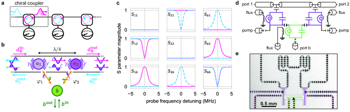
Here, we propose and experimentally demonstrate a general chiral interface — a ‘chiral coupler’ — that is suited for integration with (arbitrary) superconducting quantum devices. We approach the following discussion predominantly from a network perspective, where the goal is to route quantum states between qubits using directional emission and absorption (Fig. 1a); our circuit is, however, well-suited also for integrated noise isolation [31, 2, 34, 35, 36]. The central goals and features of our design are as follows: We target a three-port device, where two ports serve as main communication ports for propagating signals at a single communication frequency. The third port is meant to be directly coupled to a coherent quantum mode, such as a qubit; this envisioned use also motivates that we do not require a large bandwidth, but merely some degree of (static) frequency tuning capability. Our circuit is designed to be minimal, and easy to integrate with superconducting qubits of any type. Finally, the circuit supports isolation and gyration of arbitrary quantum states; in particular, we demand that the device operates linearly, and thus preserves the statistics of coherent states. The latter will allow for transmitting bosonic quantum error correction codewords for the construction of an error-correctable network [44, 45]. Linearity also allows the circuit to be used as a replacement for conventional circulators employed in established qubit measurement techniques using coherent states.
In an experimental realization of the proposed circuit we have achieved high directionality ( dB), determined through measurements of isolation and gyration. Importantly, our design consists only of a minimal set of ingredients required for demonstrating nonreciprocity [46]. As a result, we can model the device performance in quantitative agreement with a few independently calibrated circuit parameters. With the circuit parameters chosen in the device measured here, directional emission and absorption of arbitrary quantum states in a network could be achieved with an efficiency of 85%. Modest adjustment of circuit parameters will bring this efficiency to the 99%-level. The circuit presented thus provides a promising, flexible chiral interface for superconducting qubit devices for the realization of low-loss cascaded networks and for integrated noise-isolation.
Model
In a similar spirit to recently investigated giant atoms in waveguide QED [47, 48, 49, 43, 50], we realize directionality by phase-controlled interference between different emission paths. Our model consists of three modes, depicted in Fig. 1b. Two modes with identical frequency couple to a common waveguide with strength . They are spatially separated along the waveguide by a distance , where is the wavelength of the emitted radiation. Mode couples to both via parametrically controllable mode conversion, with rate and phase . A photon from may enter the waveguide via two paths: and . This setup enables phase control of the emission paths through external drives, and thus controllable interference between the paths, which is the origin of nonreciprocity here. We note that there are no special demands on the modes, besides the requirement that phase-controlled frequency conversion can be established between them. The chiral coupler could thus act as a general-purpose, narrow-band circulator that can be integrated with arbitrary memory modes.
We model the system as a three-port device, where , , are the input (output) field operators at each port (Fig. 1d). The equations of motions are
| (1) | ||||
| (2) | ||||
| (3) |
We assume for now that both and couple to the waveguide equally, i.e., , and is the coupling strength between and its port. and are the mode frequencies of and respectively. The terms in Eq. 1 and in Eq. 3 arise from a waveguide-mediated interaction between and . Crucially, this interaction must be fully eliminated for the chiral coupler to operate as a circulator [17] (Fig. 11). We can eliminate this interaction by cancelling it with a bus-mediated coupling [51, 52, 53, 54]: The terms in Eq. 1 and in Eq. 3 are the result of this coupling, arising from a static coupling between to , with
| (4) |
Here, is the static coupling between the undressed and modes, and . (and in particular, its sign) can be controlled through the detuning between the and (see Methods for details).
If the cancellation condition is met, i.e., , circulation can be seen directly from the S-matrix, which is plotted as function of probe frequency detuning at each port in Fig. 1c. We have derived the S-parameters by combining the equations of motion with the input-output relations, which are given by
| (5) | ||||
| (6) | ||||
| (7) |
Full expressions for the S-matrix as well as details of the derivation are given in the Methods section.
Circuit realization and characterization
Our model can be realized with the superconducting circuit shown in Fig. 1d,e. It consists of three modes, each containing a Superconducting Nonlinear Asymmetric Inductive eLement (SNAIL) [55] and a common transmission line. The SNAILs provide a third-order nonlinearity that we use to realize parametric frequency conversion between the modes; its frequency-dependence on external flux is used to tune mode frequencies to the operation point. This minimal circuit can be understood quantitatively with a small set of parameters. In the following, we first describe how the device parameters shown in Table 1 are extracted from experiment. Further below, we show that these parameters are sufficient to predict the circulator performance of the device in quantitative agreement with experiment.
| Qty. | Value | Description |
|---|---|---|
| \qty4.875\giga | resonant frequency of | |
| \qty4.875\giga | resonant frequency of | |
| \qty6.270\giga | resonant frequency of | |
| \qty215\kilo | internal damping of | |
| 2 | \qty1.46\mega | waveguide coupling of |
| \qty294\kilo | internal damping of | |
| 2 | \qty1.43\mega | waveguide coupling of |
| \qty588\kilo | internal damping of | |
| \qty2.51\mega | waveguide coupling of | |
| \qty1.04 | coupling cancellation ratio | |
| \qty0.70\mega | parametric coupling strength |
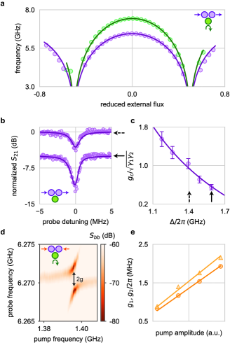
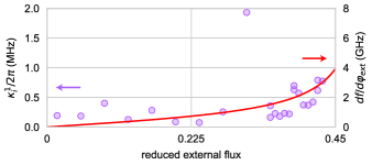
We have performed basic mode characterization at 10 mK using a vector network analyzer (VNA). In Fig. 2a we show the mode frequencies as function of external flux. We have obtained resonant frequencies, external coupling and internal damping by standard fitting of the VNA trace for each flux bias point. At the targeted operation point, and is chosen such that . Waveguide-mediated coupling is reflected in the waveguide transmission , allowing us to find the cancellation condition. For perfect cancellation and without internal damping,
| (8) |
where is the detuning of the probe signal from the mode frequency. Minimal waveguide-induced coupling corresponds to highest transmission at . To find the best operation point, we have thus measured as function of , controlled by external flux, while keeping fixed. was inferred from a fit to (see Eq. 67). Two representative VNA traces and corresponding fits are shown in Fig. 2b. We note that ideally one can expect unit transmission for perfect cancellation; finite internal damping or dephasing, however, results in residual insertion loss at . We note that in practice we cannot expect an exact matching of external coupling rates (), and the cancellation condition slightly changes: (Methods). In Fig. 2c, we show the inferred cancellation ratio as a function of , following the expected dependence. The operation point in what follows is at , where we found the best cancellation.
Next, we turn to the realization of parametric frequency conversion between modes and . By applying external pump tones at frequency we can enable effective ‘beam splitter’ Hamiltonians [56, 57, 58],
| (9) |
where the effective coupling strengths and phases are controlled by the pumps. To determine , we probe the reflection off while applying a pump with frequency ; a representative response signal is shown in Fig. 2d. At the resonance condition, , we observe an anti-crossing with a mode separation of . Coupling strengths determined in this way are shown as a function of pump amplitude in Fig. 2e. Coupling strength increases linearly with pump amplitude, in agreement with our expectation for a parametrically driven three-wave mixing element [57, 58].
Isolation and Gyration
At the operation point, applying both conversion pumps simultaneously results in interference in the loop formed by , , and the transmission line. Consequently, we expect phase-tuneable transmissions and reflections when injecting signals into a port, and monitoring emissions. In principle, this would allow measuring the full S-matrix similar to the simulated one in Figure 1c. Here, due to constraints in the wiring, we focus on and , which would directly correspond to using the device as an isolator or controllable absorber. The phase-control of these quantities is confirmation that the directionality of the device can indeed be fully controlled.
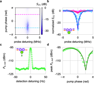
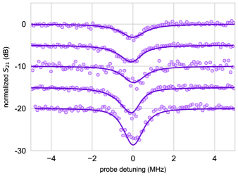
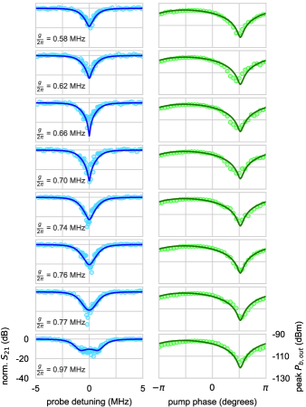
To evaluate the isolation performance of the device, we have performed measurements using a VNA, while sweeping the relative phase between the two pumps. Pump powers are set such that the conversion rates are matched, . The normalized as a function of both pump phase and probe frequency, for , is shown in Fig. 3a. changes dramatically from low to high insertion loss at zero detuning, demonstrating clearly the parametrically tuneable directionality of the chiral coupler. In Fig. 3b, we show line cuts at the “pass” and “isolation” phase settings, revealing a narrow-band isolation of at the isolation setting. We also observe a finite insertion loss of at the pass setting; this non-ideal behavior can be explained by internal decoherence, which we believe originates from flux noise (Fig. 9). We expect that this detrimental effect can be largely eliminated by a moderate adjustment of the circuit parameters (see next section for a detailed discussion). We emphasize that the isolation performance is predicted in quantitative agreement (blue and red lines in Fig. 3b) using the same parameters we have extracted from our calibration data shown in the previous section. We have repeated this measurement over a wider range of , with each measurement showing a similar level of agreement between data and theoretical prediction. The data shown in Fig. 3 were taken at the value for the best peak isolation, in agreement with theory and limited by damping. The model is presented in the Methods, and additional data are shown in Figure 13.
To directly evaluate gyration in the device, we have measured not only insertion loss between ports 1 and 2, but also the power emitted at port , , which is proportional to . The data were taken simultaneously with , using a spectrum analyzer. In this measurement, the signal emitted at port occurs at the converted frequency . Figure 3c shows detected power against detection frequency, taken at the ‘isolation’ setting indicated in Fig. 3a. The fact that a prominent peak is visible at is an indicator that isolation in corresponds to transmission in , i.e., that gyration occurs. Peak power as a function of phase is shown in Fig. 3d. The maximum emitted power coincides with the phase for the best isolation in (at ), and similarly the minimum peak matches the best transmission (at ), providing strong evidence for gyration. As with isolation, the gyration behavior is captured quantitatively, up to RF output line calibrations, by our model using the same set of parameters. Data for additional values of are presented in Fig. 13.
Parameter-dependence of performance
The above described data and model confirm that our circuit is capable of achieving very good directional performance, and that it is highly predictable. In the following, we use these insights as guide for predicting the performance of integrated devices that may be used for isolation and quantum signal routing. Specifically, we are interested in how circuit parameters can be used to tailor insertion loss and isolation, as well as the efficiency with which the chiral coupler could be used to directionally emit and absorb quantum states when integrated with a qubit, as initially envisioned in Figure 1a.
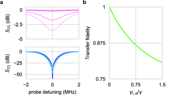
First, isolation and insertion loss are useful metrics to assess the utility of the chiral coupler as a circulator, whether stand-alone or integrated with quantum devices on a chip. We have observed that the internal damping of the SNAIL modes causes a degradation of the device performance, resulting in finite isolation as well as non-zero insertion loss as shown in Fig. 3b. The parameter governing this degradation is the ratio between internal and external damping, . Here, we assume all the modes have the same external and internal damping rate. In Fig. 4a, we show the calculated isolation and insertion loss as a function of , with device parameters similar to those used in the experiment presented above. As expected, in the limit of no internal damping the device approaches ideal behavior, i.e., perfect isolation on resonance, and no insertion loss.
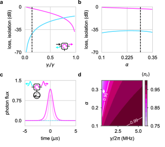
A smaller ratio can be achieved either by increasing the external coupling strength of the modes, or by reducing the internal damping rate. Increasing the external coupling by moving the modes closer to the transmission line is straight-forward. Regarding the internal damping, we have observed that measured linewidths increase significantly as frequencies are tuned away from the flux insensitive point. This observation indicates that flux noise is a key limitation of coherence (see Fig. 9). Assuming that we cannot find an effective route to reduce this noise, we are left with the option to reduce flux sensitivity and tunability; this can be achieved by reducing the SNAIL parameter [55] (see Methods). In Fig. 4b, we show the predicted isolation and insertion loss as a function of . For the calculation we have assumed that the flux noise is the only source of internal broadening of the modes, and we model this as a loss rate that depends on frequency sensitivity, . We note that flux noise can typically be expected to result in dephasing rather than energy dissipation; an explicit distinction is beyond the scope of our current work. It is worth noting that reducing will also lead to a decrease in the third order non-linearity of the SNAIL, thus lowering the parametric coupling strength for the frequency conversion process; this can be compensated by stronger drives. In summary, we predict that a modest change of design parameters and should be able to yield a dramatic improvement in both insertion loss and isolation.
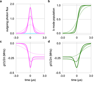
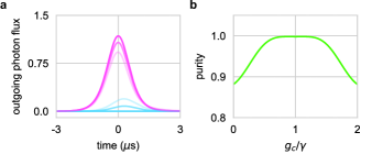
Finally, we return to our originally envisioned use case for the device, namely to act as an interface for directionally controllable emission and absorption of arbitrary quantum states encoded in traveling wavepackets. Based on our model above, we compute the predicted efficiency of on-demand, directional photon emission from . We assume that is initialized with 1 photon, and by applying temporally shaped pumps with and appropriately chosen phase difference, the photon leaves as a shaped wavepacket in the desired direction. For specifically chosen pump setting, the emitted photon flux as a function of time is shown in Fig. 4c. While the directionality of emission is near-perfect using our experimentally established parameters, efficiency is suppressed due to internal loss and dephasing. Similar to the case of insertion loss discussed above, however, we predict that high emission efficiency can be achieved by tailoring circuit parameters. In Fig. 4d we show the calculated emitted number of photons as a function of and external coupling strength , where we assume the photons are emitted from an ideal mode without decoherence. Smaller and larger result in dramatically reduced photon loss in the device. With moderate adjustment of these parameters ( MHz and ), we predict that directional photon emission and absorption with efficiencies of 99 is achievable.
Conclusions and outlook
We have demonstrated a versatile directional interface for integration with superconducting quantum circuits. In this chiral coupler, parametrically controlled interference breaks time-reversal symmetry and realizes nonreciprocity with in-situ control. The experimentally realized device displays a high degree of directionality, and we have verified its performance in both isolation and gyration measurements. Our circuit design consists of a minimal number of modes, and can be described by a simple model. With only few system parameters that can be calibrated independently, our model successfully captures the measured device performance quantitatively and without free fit parameters. Based on this model, we predict that sub-percent inefficiency is within reach when using the chiral coupler as a qubit-integrated circulator or quantum signal router, without need for significant improvement in device quality. Looking forward, directly integrating our chiral coupler with qubits on-chip will be a stepping stone for harnessing nonreciprocity for scalable quantum processors. Integration into readout circuitry, the coupler may enable an isolator-free qubit readout scheme [31, 2, 34, 35, 36]. On the other hand, using the coupler as a quantum signal routing element, it can enable driven-dissipative remote entanglement [13, 59, 60], and the transfer of arbitrary quantum states in all-to-all connected quantum networks [14, 15, 16, 61].
Acknowledgements
We acknowledge funding from the NSF Quantum Leap Challenge Institute for Hybrid Quantum Architectures and Networks (Award 2016136) and from the IBM-Illinois Discovery Accelerator Institute. Measurements were performed on a device fabricated by the Superconducting Qubits at Lincoln Laboratory (SQUILL) Foundry at MIT Lincoln Laboratory, with funding from the Laboratory for Physical Sciences (LPS) Qubit Collaboratory. We thank R. McDermott, S. Chakram and B. Du for advice on flux lines; S. Mandal, A. Baptista, S. Cross, and S. Rani for experimental assistance; and S. Shankar and A. Kou for critical reading of the manuscript.
Author contributions
X.C. designed the device, developed the theory model, conducted the experiment, and analysed the data. A.I. designed the on-chip flux line. M.M. contributed to the model for absorption and emission. K.S. contributed to measurement and data analysis. The paper was written by X.C. and W.P., with comments from all authors. The work was conceived and supervised by W.P.
Methods
Model
Here we give a detailed derivation of our model for the chiral coupler. We first treat the chiral coupler as a three-port device and derive the input-output relations for each port. Then the full S-matrix of the device is derived using these input-output relations. We then discuss the waveguide-mediated coupling and how to cancel it with a bus-mediated coupling. Finally, we discuss the model for quantum state transfer in a cascaded system of two chiral emitters/absorbers implemented with our chiral coupler. The symbols used in the following sections are summarized in Table 2.
| Sym. | Desc. |
|---|---|
| frq. of and at operation point | |
| frq. of at operation point | |
| ladder operators for | |
| ladder operators for | |
| pump frq. for the conversion process | |
| rate of conversion between and | |
| phase of conversion between and | |
| ladder ops. for right (left) propagating modes in the common transmission line | |
| ladder ops. for the propagating mode in the semi-infinite transmission line on ’s port | |
| external coupling of to left and right propagating modes | |
| external coupling of both modes if they are equal | |
| internal damping of mode | |
| internal damping of both modes if equal | |
| external coupling of | |
| internal coupling of | |
| position of along the common transmission line | |
| speed of light in the transmission line |
Input-output relations
We first assume that there is no internal damping in the device. We treat the chiral coupler as a three-port device, as shown in Fig. 1b,d. The full Hamiltonian can be written as:
| (10) |
describes the system Hamiltonian for the chiral coupler. Here, describes the and modes:
| (11) |
describes the parametric frequency conversion process:
| (12) |
and describes the bus-mediated coupling between and mode:
| (13) |
For clarity we write as a separate term, rather than absorbing it into the system Hamiltonian. It is used to cancel the waveguide-mediated coupling; its origin and how cancellation is achieved is discussed further below.
The second term on the left-hand side of Eq. 10 is the bath Hamiltonian:
| (14) |
The transmission line mode operators satisfy commutation relations , where . The system-bath interaction is given by:
| (15) |
Here we use the first Markov approximation, that is, the coupling strength is independent of frequency.
The input-output relation for the port can be obtained in the usual way [8]:
| (16) |
and the dynamics for are described by:
| (17) |
The equations of motion for mode and and input-output relation of the transmission line modes can be obtained in a similar way. We first set and define for simplicity (without loss of generality). The equation of motion for () is given by:
| (18) |
The solution is:
| (19) |
where is the initial value for at frequency . Similarly, the equation of motion for is given by:
| (20) |
To solve the equation for , we need the last two terms in Eq. 20, which follow from Eq. 19. For , for example, we obtain:
| (21) |
For simplicity, we set . We write the input field modes propagating in the L(R) direction as:
| (22) |
Then Eq. 21 can be simplified to:
| (23) |
where if , and vice versa. is the Heaviside step-function. We have used the -function representation
| (24) |
in the above derivation. The integral for can be obtained in the same way:
| (25) |
We use the free-evolution approximation, . This approximation is valid when the delay time for photons from to is much shorter than the time scale of the evolution of the system. The operator equation for can then be written as:
| (26) |
The term corresponds to the waveguide-mediated coupling . In order to derive the input-output relation for the propagating mode in the transmission line, we note that the solution to Eq. 18 can be written differently if we choose to integrate from a time :
| (27) |
Consider the integral :
| (28) |
and we write the output modes as:
| (29) |
We then arrive at the input-output relation for the leftward propagating modes:
| (30) |
Similarly, we obtain for the rightward propagating modes:
| (31) |
The spatial separation between and mode is , and we can set . By applying this condition into Eq. 16, Eq. 17, Eq. 26, Eq. 30, Eq. 31 and using the expression for , , , we recover the input output relation and equation of motion discussed in the Model section of the main text.
S-matrix
The S-matrix of the chiral coupler can be obtained by solving the input-output relation and operator equations together in the frequency domain. We start from Eq. 1, Eq. 2, and Eq. 3. Taking the Fourier transform on both sides, we obtain:
| (32) | ||||
| (33) | ||||
| (34) |
where and are probe frequencies for the and modes; these are frequencies close to the resonant frequencies and , in practice. The parametric conversion process requires the frequency matching condition ; we define a frequency detuning . Then we obtain:
| (35) | ||||
| (36) | ||||
| (37) |
We omit the frequency dependent for the operators for simplicity, as now they are all measured at their corresponding probing frequencies. These equations together with input output relations yield the S-matrix of the chiral coupler. The S parameters are given by (here, for simplicity, let , , and ):
| (38) |
where we have introduced , , , , , and . Each S parameter is obtained with other input signals set to 0 and the above result is used to generate the S-matrix in Fig. 1c with . For the more realistic case where , a similar solution can be obtained by choosing .
Cancellation of waveguide-mediated coupling
As explained previously, there is a waveguide-mediated coupling between the and modes that needs to be cancelled. The coupling term arises from the second term on the right hand side of Eq. 20, which is due to the interaction between and bath (the common transmission line) modes. This term reads:
| (39) |
which can be effectively written as
| (40) |
Specifically for our case, where and assuming , we have:
| (41) |
Therefore this term acts as an effective interaction term between and , which may be absorbed into the system Hamiltonian as an extra coupling term: . In the derivation of this interaction, we only assume a general system-bath interaction, as given in Eq. 15. As shown explicitly in Fig. 11, this extra coupling is detrimental to the directionality of the chiral coupler, and needs to be eliminated.
The cancellation is realized by exploiting a ‘quantum bus’ coupling [51, 52, 53, 54] between the and modes through the mode. To understand the origin of this interaction, let us consider the three modes , and , with coupling between each other. The Hamiltonian can be written as:
| (42) |
where for simplicity we assume that the modes have the same frequency () and the same coupling () to the mode. We also assume a dispersive coupling regime, i.e., , where is the frequency detuning between the modes. We can then apply a Schrieffer-Wolff transformation. The transfer matrix is given by:
| (43) |
The Hamiltonian transforms as
| (44) |
and we use the Baker-Campbell-Haussdorf formula:
| (45) |
Since , we can treat the mode couplings as a perturbation, and write the Hamiltonian as:
| (46) |
where and . Up to the first order in , the transformed Hamiltonian in the dressed basis is now:
| (47) |
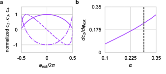
where , and are the new mode frequencies in the dressed basis. Note that we have already worked in this dressed basis in the main text and derivations in previous sections, with the ′ omitted. This extra coupling between the two modes, is generated because both and modes are coupled to the mode. Together with the original coupling between the two modes, we reach the “cancellation coupling”, , in the main text:
| (48) |
Its frequency tunable nature allows us to reach the desired coupling strength by biasing to the right frequency. Equation Eq. 48 is used for fitting the cancellation ratio data shown in Fig. 2c.
On-demand directional photon emission and absorption
To investigate quantum signal routing, we consider the case of on-demand photon emission and absorption: is initialized with one excitation, and we aim to release this excitation coherently as traveling photon, with directional control. Vice versa, we want the ability to absorb traveling wavepackets into excitations in . In general, this requires a tunable coupling between the mode and its bath [12]. These tasks can be realized with the chiral coupler by parametrically controlling the couplings between the mode and two modes.
Here, we provide a semi-classical time-domain solution to this question by solving the input-output relations and equations of motion for the mode operators. The target wave packet is chosen to have the form
| (49) |
where is the full width at half maximum for the wave packet in the time domain. The form is chosen because it provides an analytic solution for the shape of the parametric pumps [17]; other shapes may be solved for numerically. For the on-demand directional photon emission, we first initialize the mode in a coherent state with one photon on average, i.e., . In in the equations of motion and input-output relations, we set all inputs to 0, and solve with initial condition . The analytically obtained form of the magnitude of the parametric pump is given by:
| (50) |
The solutions for the pumps and emitted field as a function of time, for the case of a rightward emitted wavepacket, are shown in Fig. 5a,c. Directionality is achieved by controlling the relative phases between the two pumps.
On-demand photon absorption can be calculated in a similar way. Because the incoming wave packet is time-symmetric, the absorption process is the time-inverse of the emission. Absorption can thus be achieved by setting . When solving the equations of motion, we set , keep all other inputs 0, and initial conditions are . Example solutions for photon absorption are shown in Fig. 5b,d.
These calculations provide semi-classical evidence for directional emission and absorption capability of the chiral coupler. To discuss its performance (e.g., transfer fidelity) when routing quantum signals, we present a quantum description below.
Quantum state transfer
We begin by deriving the quantum master equation for a single chiral coupler. Similar to Eq. 20, we now consider the equation for an operator :
| (51) |
The second term on the RHS yields
| (52) |
where we used Eq. 23 and Eq. 25, and a similar result for from input-output theory. Now consider the expectation value of this operator in the Schrodinger picture. We use the cyclic invariance of the trace operation and we also assume the initial state of the propagating mode to be the vacuum state, thus setting , , and :
| (53) |
Because the operator is an arbitrary local operator of the chiral coupler, its expectation value can be obtained independently of the partial trace of the propagating modes. Thus, the reduced master equation for the chiral coupler can be written as:
| (54) |
where is the density matrix of the chiral coupler, is the partial trace with respect to the propagating modes and corresponds to the waveguide-mediated coupling between the modes. When the physical separation between the modes is and , the Hamiltonian will lead to the equations we used in the main text.
Next, we can derive from this the full quantum master equation of two chiral couplers that share the same transmission line. The bath Hamiltonian for this case is:
| (55) |
and the system-bath interaction Hamiltonian is:
| (56) |
where is the ladder operator for the propagating mode in the semi- infinite transmission line on b’s port of the th chiral coupler, and is the external coupling of the corresponding mode. The input-output relations for the modes remain the same as the single coupler case. The solution for the propagating mode in the transmission line is given by:
| (57) |
Then, for an arbitrary local operator of the chiral coupler, we can obtain:
| (58) |
Then consider the same expectation value and set all the initial state of the propagating mode to be the vacuum state:
| (59) |
This reduces to a master equation for the two connected chiral couplers:
| (60) |
where is the waveguide-mediated coupling between the modes.
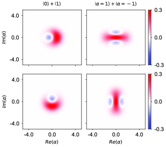
Using the master equation Eq. 60 we can now compute numerically state transfer fidelities. To illustrate this here, we consider an ideal situation (no experimental imperfections), and two different types of initial states: Fock state superpositions, and cat states (i.e., coherent state superpositions). At the , the mode in the first chiral coupler is initialized with the chosen initial state. The parametric pumps for both chiral coupler are then activated, with a phase setting such that the first device emits the state to the right, while the second one absorbs radiation coming from left. The amplitude of the pumps are set according to Eq. 50, with and for emission and absorption processes respectively. The calculated Wigner functions for the states sent and received by the two chiral couplers are shown in Fig. 6. As the model only requires linear modes with parametric interactions, the chiral coupler is not limited within the basis of and , but allows us to work with different encoding schemes, which shows its potential to route complex quantum states throughout a network.
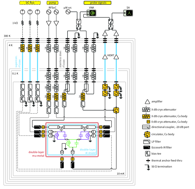
Experimental setup
The circuit was fabricated by the Superconducting Qubits at Lincoln Laboratory (SQUILL) Foundry at MIT Lincoln Laboratory. The designed SNAIL junction parameters are: nH ( value for one junction on the three-junction arm) and for and ; nH and for .
Performance analysis and imperfections
We have already established the model for the chiral coupler in the ideal case. We now go one step further and discuss performance limits imposed by non-ideal parameters. We first discuss impact of internal damping rate, and how the performance can be improved by using a SNAIL with smaller . We then discuss the effect of imperfect cancellation of waveguide-mediated coupling.
Effect of damping
Including the effect from finite internal damping, the relevant equations of motion become:
| (61) | ||||
| (62) | ||||
| (63) |
where are the internal damping rates of , respectively. The behavior of the chiral coupler with a finite internal Q can then be calculated by solving this set of equations together with the input-output relations. Predictions for with finite internal damping rates are shown in Fig. 8a. The result shown in Fig. 4a is obtained by finding the minimum of over a larger range of the ratio. The increase of the internal damping rate of the SNAIL mode thus clearly results in a decrease of both insertion loss and isolation of the chiral coupler.
This internal loss also impacts state transfer fidelity in a cascaded system. We consider an example where the initial state is transferred from the first chiral coupler to the second, and the process is simulated using the full quantum model developed in the previous section. The transfer fidelity as a function of is shown in Fig. 8b.
Flux noise
Lowering damping of the internal modes of the chiral coupler would immediately result in improved performance. As shown in Fig. 9, the damping rate measured on mode displays a trend that qualitatively matches its flux sensitvity. Because there is an obvious difference ( factor of 3) in the SNAIL internal Q between the flux insensitive point and the operation point, we believe that flux noise is a major reason for internal damping rates, and thus of lowered performance. One promising approach to reduce the impact of the flux noise is to use a SNAIL with a smaller .
The SNAIL is designed to be a dipole circuit element with third order nonlinearity and minimal fourth order nonlinearity [55]. A typical SNAIL is a superconducting loop of 3 Josephson junctions and a single smaller junction shunted by a large capacitor. The whole loop is threaded with magnetic flux . The Hamiltonian for the SNAIL is:
| (64) |
where is the charging energy of the SNAIL mode, is the charge operator, is the Josephson energy is of the small junction and is the ratio between Josephson energy between the large and small junctions, is the phase over the small junction and is the reduced external flux. We an expand the inductive part of this Hamiltonian near the energy minimum point ():
| (65) |
where the coefficients for each order are functions of and , . As an example, normalized SNAIL coefficients as a function of external flux calulated with the design values of are shown in Fig. 10a.
Ideally, the SNAIL is operated near the flux point where the fourth order nonlinearity is cancelled. Given the coefficients above, the SNAIL mode can then be quantized, with the resonant frequency . The dephasing rate of the SNAIL is a function of the flux noise power spectrum, :
| (66) |
Here we assume the flux noise is the same across the frequency tuning range. Then, the dephasing rate is set by the frequency sensitivity to the external flux, which is proportional to the derivative of SNAIL coefficient with respect to the external flux. This derivative is shown in Fig. 10b as a function of . In Fig. 4d of the main text, the impact of is estimated by setting the internal damping rate proportional to the value at according to the calculated derivative value. We note that by choosing a SNAIL with , we could already see an improvement of factor of 3 from our current device.
Effect of imperfect waveguide-mediated coupling cancellation
Another important factor that affects the performance of the chiral coupler is the imperfect cancellation of the waveguide-mediated coupling, i.e., . The effect of this case be seen, for example, in imperfect directional emission of shaped wavepackets. In Fig. 11a we show the calculated outgoing photon flux as a function of time after is initialized with one photon, and drives are applied to emit the state. The ‘pitched’ photon is partially emitted into the wrong direction as the coupling cancellation deviates from the ideal case. This leads to decoherence in a network: The purity of the state received by a second party (when attempting to transfer ) as function of the ratio is shown in Fig. 11b.
Calibrating waveguide-mediate coupling cancellation
The degree of the cancellation is inferred by measuring the trace when both modes are biased at operation point without applying pumps. Ideally, unit transmission is achieved at the cancellation point, and a dip will emerge as we deviate from it. The depth of the dip reflects the degree of the cancellation. In practice, we still see an finite dip near the perfect cancellation point, due to the internal damping rate of the SNAIL mode. With finite and , at becomes
| (67) |
It is easy to verify that with , , this turns back into the ideal case Eq. 38.
Isolation and gyration performance
By taking into account all parameters and models discussed above, our theory shows good quantitative agreement with measured isolation and gyration data across a wide range of pump powers. In Fig. 13, we show both isolation and gyration data obtained at different pump powers. The theory curves are obtained with parameters independently calibrated as discussed in the main text. was obtained by extrapolation of the data shown in Fig. 2e. We stress that a single set of circuit parameters (Table 1 in the main text) was used for predicting all data in Fig. 13.
References
- Boissonneault et al. [2009] M. Boissonneault, J. M. Gambetta, and A. Blais, Dispersive regime of circuit QED: Photon-dependent qubit dephasing and relaxation rates, Phys. Rev. A 79, 013819 (2009).
- Abdo et al. [2019] B. Abdo, N. T. Bronn, O. Jinka, S. Olivadese, A. D. Córcoles, V. P. Adiga, M. Brink, R. E. Lake, X. Wu, D. P. Pappas, and J. M. Chow, Active protection of a superconducting qubit with an interferometric Josephson isolator, Nat Commun 10, 3154 (2019).
- DiVincenzo [2009] D. P. DiVincenzo, Fault-tolerant architectures for superconducting qubits, Phys. Scr. T137, 014020 (2009).
- Fowler et al. [2012] A. G. Fowler, M. Mariantoni, J. M. Martinis, and A. N. Cleland, Surface codes: Towards practical large-scale quantum computation, Phys. Rev. A 86, 032324 (2012).
- Devoret and Schoelkopf [2013] M. H. Devoret and R. J. Schoelkopf, Superconducting Circuits for Quantum Information: An Outlook, Science 339, 1169 (2013).
- Walter et al. [2017] T. Walter, P. Kurpiers, S. Gasparinetti, P. Magnard, A. Potočnik, Y. Salathé, M. Pechal, M. Mondal, M. Oppliger, C. Eichler, and A. Wallraff, Rapid High-Fidelity Single-Shot Dispersive Readout of Superconducting Qubits, Phys. Rev. Appl. 7, 054020 (2017).
- Sunada et al. [2022] Y. Sunada, S. Kono, J. Ilves, S. Tamate, T. Sugiyama, Y. Tabuchi, and Y. Nakamura, Fast Readout and Reset of a Superconducting Qubit Coupled to a Resonator with an Intrinsic Purcell Filter, Phys. Rev. Appl. 17, 044016 (2022).
- Gardiner and Collett [1985] C. W. Gardiner and M. J. Collett, Input and output in damped quantum systems: Quantum stochastic differential equations and the master equation, Phys. Rev. A 31, 3761 (1985).
- Gardiner [1993] C. W. Gardiner, Driving a quantum system with the output field from another driven quantum system, Phys. Rev. Lett. 70, 2269 (1993).
- Carmichael [1993] H. J. Carmichael, Quantum trajectory theory for cascaded open systems, Phys. Rev. Lett. 70, 2273 (1993).
- Lodahl et al. [2017] P. Lodahl, S. Mahmoodian, S. Stobbe, A. Rauschenbeutel, P. Schneeweiss, J. Volz, H. Pichler, and P. Zoller, Chiral quantum optics, Nature 541, 473 (2017).
- Cirac et al. [1997] J. I. Cirac, P. Zoller, H. J. Kimble, and H. Mabuchi, Quantum State Transfer and Entanglement Distribution among Distant Nodes in a Quantum Network, Phys. Rev. Lett. 78, 3221 (1997).
- Stannigel et al. [2012] K. Stannigel, P. Rabl, and P. Zoller, Driven-dissipative preparation of entangled states in cascaded quantum-optical networks, New J. Phys. 14, 063014 (2012).
- Axline et al. [2018] C. J. Axline, L. D. Burkhart, W. Pfaff, M. Zhang, K. Chou, P. Campagne-Ibarcq, P. Reinhold, L. Frunzio, S. M. Girvin, L. Jiang, M. H. Devoret, and R. J. Schoelkopf, On-demand quantum state transfer and entanglement between remote microwave cavity memories, Nature Phys 14, 705 (2018).
- Campagne-Ibarcq et al. [2018] P. Campagne-Ibarcq, E. Zalys-Geller, A. Narla, S. Shankar, P. Reinhold, L. Burkhart, C. Axline, W. Pfaff, L. Frunzio, R. J. Schoelkopf, and M. H. Devoret, Deterministic Remote Entanglement of Superconducting Circuits through Microwave Two-Photon Transitions, Phys. Rev. Lett. 120, 200501 (2018).
- Kurpiers et al. [2018] P. Kurpiers, P. Magnard, T. Walter, B. Royer, M. Pechal, J. Heinsoo, Y. Salathé, A. Akin, S. Storz, J.-C. Besse, S. Gasparinetti, A. Blais, and A. Wallraff, Deterministic quantum state transfer and remote entanglement using microwave photons, Nature 558, 264 (2018).
- Gheeraert et al. [2020] N. Gheeraert, S. Kono, and Y. Nakamura, Programmable directional emitter and receiver of itinerant microwave photons in a waveguide, Phys. Rev. A 102, 053720 (2020).
- Mahoney et al. [2017] A. C. Mahoney, J. I. Colless, S. J. Pauka, J. M. Hornibrook, J. D. Watson, G. C. Gardner, M. J. Manfra, A. C. Doherty, and D. J. Reilly, On-Chip Microwave Quantum Hall Circulator, Phys. Rev. X 7, 011007 (2017).
- Wang et al. [2021] Y.-Y. Wang, S. van Geldern, T. Connolly, Y.-X. Wang, A. Shilcusky, A. McDonald, A. A. Clerk, and C. Wang, Low-Loss Ferrite Circulator as a Tunable Chiral Quantum System, Phys. Rev. Appl. 16, 064066 (2021).
- Wang et al. [2024] Y.-Y. Wang, Y.-X. Wang, S. van Geldern, T. Connolly, A. A. Clerk, and C. Wang, Dispersive nonreciprocity between a qubit and a cavity, Science Advances 10, eadj8796 (2024).
- Owens et al. [2022] J. C. Owens, M. G. Panetta, B. Saxberg, G. Roberts, S. Chakram, R. Ma, A. Vrajitoarea, J. Simon, and D. I. Schuster, Chiral cavity quantum electrodynamics, Nat. Phys. 18, 1048 (2022).
- Koch et al. [2010] J. Koch, A. A. Houck, K. L. Hur, and S. M. Girvin, Time-reversal-symmetry breaking in circuit-QED-based photon lattices, Phys. Rev. A 82, 043811 (2010).
- Metelmann and Clerk [2015] A. Metelmann and A. A. Clerk, Nonreciprocal Photon Transmission and Amplification via Reservoir Engineering, Phys. Rev. X 5, 021025 (2015).
- Kerckhoff et al. [2015] J. Kerckhoff, K. Lalumière, B. J. Chapman, A. Blais, and K. W. Lehnert, On-Chip Superconducting Microwave Circulator from Synthetic Rotation, Phys. Rev. Applied 4, 034002 (2015).
- Kamal and Metelmann [2017] A. Kamal and A. Metelmann, Minimal Models for Nonreciprocal Amplification Using Biharmonic Drives, Phys. Rev. Appl. 7, 034031 (2017).
- Lecocq et al. [2017] F. Lecocq, L. Ranzani, G. A. Peterson, K. Cicak, R. W. Simmonds, J. D. Teufel, and J. Aumentado, Nonreciprocal Microwave Signal Processing with a Field-Programmable Josephson Amplifier, Phys. Rev. Applied 7, 024028 (2017).
- Müller et al. [2018] C. Müller, S. Guan, N. Vogt, J. H. Cole, and T. M. Stace, Passive On-Chip Superconducting Circulator Using a Ring of Tunnel Junctions, Phys. Rev. Lett. 120, 213602 (2018).
- [28] M. Naghiloo, K. Peng, Y. Ye, G. Cunningham, and K. P. O’Brien, Broadband Microwave Isolation with Adiabatic Mode Conversion in Coupled Superconducting Transmission Lines, arxiv:2103.07793 .
- [29] Y. Zhuang, C. Gaikwad, D. Kowsari, K. Murch, and A. Nagulu, Superconducting Non-Reciprocity Based on Time-Modulated Coupled-Resonator Systems, arxiv:2307.01853 .
- Sliwa et al. [2015] K. M. Sliwa, M. Hatridge, A. Narla, S. Shankar, L. Frunzio, R. J. Schoelkopf, and M. H. Devoret, Reconfigurable Josephson Circulator/Directional Amplifier, Phys. Rev. X 5, 041020 (2015).
- Chapman et al. [2017] B. J. Chapman, E. I. Rosenthal, J. Kerckhoff, B. A. Moores, L. R. Vale, J. A. B. Mates, G. C. Hilton, K. Lalumière, A. Blais, and K. W. Lehnert, Widely Tunable On-Chip Microwave Circulator for Superconducting Quantum Circuits, Phys. Rev. X 7, 041043 (2017).
- Ranzani and Aumentado [2019] L. Ranzani and J. Aumentado, Circulators at the Quantum Limit: Recent Realizations of Quantum-Limited Superconducting Circulators and Related Approaches, IEEE Microwave 20, 112 (2019).
- Huang et al. [2022] R. Huang, X. Geng, G. Dai, L. Yang, J. Liu, and W. Chen, Design and fabrication of integrated superconducting isolator-circulator-isolator chip, Microelectronic Engineering 263, 111844 (2022).
- Beck et al. [2023] M. Beck, M. Selvanayagam, A. Carniol, S. Cairns, and C. Mancini, Wideband Josephson Parametric Isolator, Phys. Rev. Appl. 20, 034054 (2023).
- Kwende et al. [2023] R. Kwende, T. White, and O. Naaman, Josephson parametric circulator with same-frequency signal ports, 200 MHz bandwidth, and high dynamic range, Applied Physics Letters 122, 224001 (2023).
- Navarathna et al. [2023] R. Navarathna, D. T. Le, A. R. Hamann, H. D. Nguyen, T. M. Stace, and A. Fedorov, Passive Superconducting Circulator on a Chip, Phys. Rev. Lett. 130, 037001 (2023).
- Guimond et al. [2020] P.-O. Guimond, B. Vermersch, M. L. Juan, A. Sharafiev, G. Kirchmair, and P. Zoller, A unidirectional on-chip photonic interface for superconducting circuits, npj Quantum Inf 6, 1 (2020).
- Zhang et al. [2021] Y.-X. Zhang, C. R. i Carceller, M. Kjaergaard, and A. S. Sørensen, Charge-Noise Insensitive Chiral Photonic Interface for Waveguide Circuit QED, Phys. Rev. Lett. 127, 233601 (2021).
- Redchenko et al. [2023] E. S. Redchenko, A. V. Poshakinskiy, R. Sett, M. Žemlička, A. N. Poddubny, and J. M. Fink, Tunable directional photon scattering from a pair of superconducting qubits, Nat Commun 14, 2998 (2023).
- Kannan et al. [2023] B. Kannan, A. Almanakly, Y. Sung, A. Di Paolo, D. A. Rower, J. Braumüller, A. Melville, B. M. Niedzielski, A. Karamlou, K. Serniak, A. Vepsäläinen, M. E. Schwartz, J. L. Yoder, R. Winik, J. I.-J. Wang, T. P. Orlando, S. Gustavsson, J. A. Grover, and W. D. Oliver, On-demand directional microwave photon emission using waveguide quantum electrodynamics, Nat. Phys. 19, 394 (2023).
- Joshi et al. [2023] C. Joshi, F. Yang, and M. Mirhosseini, Resonance Fluorescence of a Chiral Artificial Atom, Phys. Rev. X 13, 021039 (2023).
- [42] A. Yen, Y. Ye, K. Peng, J. Wang, G. Cunningham, M. Gingras, B. M. Niedzielski, H. Stickler, K. Serniak, M. E. Schwartz, and K. P. O’Brien, All-Pass Readout for Robust and Scalable Quantum Measurement, arxiv:2403.01375 .
- Kannan et al. [2020] B. Kannan, M. J. Ruckriegel, D. L. Campbell, A. Frisk Kockum, J. Braumüller, D. K. Kim, M. Kjaergaard, P. Krantz, A. Melville, B. M. Niedzielski, A. Vepsäläinen, R. Winik, J. L. Yoder, F. Nori, T. P. Orlando, S. Gustavsson, and W. D. Oliver, Waveguide quantum electrodynamics with superconducting artificial giant atoms, Nature 583, 775 (2020).
- Ofek et al. [2016] N. Ofek, A. Petrenko, R. Heeres, P. Reinhold, Z. Leghtas, B. Vlastakis, Y. Liu, L. Frunzio, S. M. Girvin, L. Jiang, M. Mirrahimi, M. H. Devoret, and R. J. Schoelkopf, Extending the lifetime of a quantum bit with error correction in superconducting circuits, Nature 536, 441 (2016).
- Sivak et al. [2023] V. V. Sivak, A. Eickbusch, B. Royer, S. Singh, I. Tsioutsios, S. Ganjam, A. Miano, B. L. Brock, A. Z. Ding, L. Frunzio, S. M. Girvin, R. J. Schoelkopf, and M. H. Devoret, Real-time quantum error correction beyond break-even, Nature 616, 50 (2023).
- Clerk [2022] A. Clerk, Introduction to quantum non-reciprocal interactions: From non-Hermitian Hamiltonians to quantum master equations and quantum feedforward schemes, SciPost Physics Lecture Notes , 044 (2022).
- Frisk Kockum et al. [2014] A. Frisk Kockum, P. Delsing, and G. Johansson, Designing frequency-dependent relaxation rates and Lamb shifts for a giant artificial atom, Phys. Rev. A 90, 013837 (2014).
- Kockum et al. [2018] A. F. Kockum, G. Johansson, and F. Nori, Decoherence-Free Interaction between Giant Atoms in Waveguide Quantum Electrodynamics, Phys. Rev. Lett. 120, 140404 (2018).
- Vadiraj et al. [2021] A. M. Vadiraj, A. Ask, T. G. McConkey, I. Nsanzineza, C. W. S. Chang, A. F. Kockum, and C. M. Wilson, Engineering the level structure of a giant artificial atom in waveguide quantum electrodynamics, Phys. Rev. A 103, 023710 (2021).
- Yin and Liao [2023] X.-L. Yin and J.-Q. Liao, Generation of two-giant-atom entanglement in waveguide-QED systems, Phys. Rev. A 108, 023728 (2023).
- Majer et al. [2007] J. Majer, J. M. Chow, J. M. Gambetta, J. Koch, B. R. Johnson, J. A. Schreier, L. Frunzio, D. I. Schuster, A. A. Houck, A. Wallraff, A. Blais, M. H. Devoret, S. M. Girvin, and R. J. Schoelkopf, Coupling superconducting qubits via a cavity bus, Nature 449, 443 (2007).
- Chen et al. [2014] Y. Chen, C. Neill, P. Roushan, N. Leung, M. Fang, R. Barends, J. Kelly, B. Campbell, Z. Chen, B. Chiaro, A. Dunsworth, E. Jeffrey, A. Megrant, J. Y. Mutus, P. J. J. O’Malley, C. M. Quintana, D. Sank, A. Vainsencher, J. Wenner, T. C. White, M. R. Geller, A. N. Cleland, and J. M. Martinis, Qubit Architecture with High Coherence and Fast Tunable Coupling, Phys. Rev. Lett. 113, 220502 (2014).
- Lu et al. [2017] Y. Lu, S. Chakram, N. Leung, N. Earnest, R. K. Naik, Z. Huang, P. Groszkowski, E. Kapit, J. Koch, and D. I. Schuster, Universal Stabilization of a Parametrically Coupled Qubit, Phys. Rev. Lett. 119, 150502 (2017).
- Yan et al. [2018] F. Yan, P. Krantz, Y. Sung, M. Kjaergaard, D. L. Campbell, T. P. Orlando, S. Gustavsson, and W. D. Oliver, Tunable Coupling Scheme for Implementing High-Fidelity Two-Qubit Gates, Phys. Rev. Appl. 10, 054062 (2018).
- Frattini et al. [2017] N. E. Frattini, U. Vool, S. Shankar, A. Narla, K. M. Sliwa, and M. H. Devoret, 3-wave mixing Josephson dipole element, Applied Physics Letters 110, 222603 (2017).
- Aumentado [2020] J. Aumentado, Superconducting Parametric Amplifiers: The State of the Art in Josephson Parametric Amplifiers, IEEE Microwave Magazine 21, 45 (2020).
- Chapman et al. [2023] B. J. Chapman, S. J. de Graaf, S. H. Xue, Y. Zhang, J. Teoh, J. C. Curtis, T. Tsunoda, A. Eickbusch, A. P. Read, A. Koottandavida, S. O. Mundhada, L. Frunzio, M. Devoret, S. Girvin, and R. Schoelkopf, High-On-Off-Ratio Beam-Splitter Interaction for Gates on Bosonically Encoded Qubits, PRX Quantum 4, 020355 (2023).
- Zhou et al. [2023] C. Zhou, P. Lu, M. Praquin, T.-C. Chien, R. Kaufman, X. Cao, M. Xia, R. S. K. Mong, W. Pfaff, D. Pekker, and M. Hatridge, Realizing all-to-all couplings among detachable quantum modules using a microwave quantum state router, npj Quantum Inf 9, 1 (2023).
- Pichler et al. [2015] H. Pichler, T. Ramos, A. J. Daley, and P. Zoller, Quantum optics of chiral spin networks, Phys. Rev. A 91, 042116 (2015).
- Lingenfelter et al. [2024] A. Lingenfelter, M. Yao, A. Pocklington, Y.-X. Wang, A. Irfan, W. Pfaff, and A. A. Clerk, Exact Results for a Boundary-Driven Double Spin Chain and Resource-Efficient Remote Entanglement Stabilization, Phys. Rev. X 14, 021028 (2024).
- Ai et al. [2022] H. Ai, Y.-Y. Fang, C.-R. Feng, Z. Peng, and Z.-L. Xiang, Multinode State Transfer and Nonlocal State Preparation via a Unidirectional Quantum Network, Phys. Rev. Appl. 17, 054021 (2022).
- Krinner et al. [2019] S. Krinner, S. Storz, P. Kurpiers, P. Magnard, J. Heinsoo, R. Keller, J. Lütolf, C. Eichler, and A. Wallraff, Engineering cryogenic setups for 100-qubit scale superconducting circuit systems, EPJ Quantum Technology 6, 2 (2019).
- [63] L. Stefanazzi, K. Treptow, N. Wilcer, C. Stoughton, S. Montella, C. Bradford, G. Cancelo, S. Saxena, H. Arnaldi, S. Sussman, A. Houck, A. Agrawal, H. Zhang, C. Ding, and D. I. Schuster, The QICK (Quantum Instrumentation Control Kit): Readout and control for qubits and detectors, arxiv:2110.00557 .