Gate and flux tunable Josephson element in proximitized junctions
Abstract
Hybrid superconductor-semiconductor Josephson field-effect transistors (JoFETs) function as Josephson junctions with a gate-tunable critical current. Additionally, they can feature a non-sinusoidal current-phase relation (CPR) containing multiple harmonics of the superconducting phase difference, a so-far underutilized property. In this work, we exploit this multi-harmonicity to create a Josephson circuit element with an almost perfectly -periodic CPR, indicative of a largely dominant charge-4e supercurrent transport. Such a Josephson element was recently proposed as the basic building block of a protected superconducting qubit. Here, it is realized using a superconducting quantum interference device (SQUID) with low-inductance aluminum arms and two nominally identical JoFETs. The latter are fabricated from a SiGe/Ge/SiGe quantum-well heterostructure embedding a high-mobility two-dimensional hole gas. By carefully adjusting the JoFET gate voltages and finely tuning the magnetic flux through the SQUID close to half a flux quantum, we achieve a regime where the component accounts for more than of the total supercurrent. This result demonstrates a new promising route for the realization of superconducting qubits with enhanced coherence properties.
I Introduction
Quantum information processing requires qubits with long coherence time enabling high fidelity quantum gates. Over the past two decades, superconducting circuits have led to the realization of quantum processors of ever-growing size made of qubits with steadily improving fidelities [1]. This way, superconducting qubits have become one of the most advanced physical platforms for quantum computing. Progress has been driven by material engineering and optimization, as well as by the development of new device concepts capable of providing a growing level of protection against noise sources in the environment [2]. Qubit protection against relaxation and dephasing processes can be granted from the symmetry properties of the qubit Hamiltonian. In this direction, a variety of possible solutions have been proposed and only partly explored [3, 4, 5, 6, 7, 8, 9]. One of the leading ideas is to create superconducting qubits whose two lowest energy states are associated with odd and even numbers of Cooper pairs in a superconducting island, respectively. Due to the different parity, these states are orthogonal to each other in both charge and phase space [10, 11, 12, 13, 14, 15, 16, 17]. This type of parity-protected qubit requires a parity-preserving Josephson element that only allows the coherent transfer of correlated pairs of Cooper pairs, which translates into devising a Josephson circuit with a -periodic, sin(2-) current phase relation (CPR).
Some proposals to engineer such a qubits rely on conventional Josephson junctions, either arranged into large arrays [12] or embedded in a superconducting quantum interference device (SQUID) together with extremely large inductances [13]. The practical realisation of these ideas is technologically challenging and some significant experimental progress was only recently reported [17]. Another approach is to leverage the multi-harmonic CPR and the gate tunability superconductor(S)-semiconductor(Sm) Josephson field-effect transistors with [18, 19, 20, 21, 22, 23, 24, 25, 26]. Various signatures of Josephson elements were recently reported [27, 28, 29] and harnessed to demonstrate some first experimental evidence of parity protection [14]. However, a direct measurement of a CPR and precise quantitative evaluation of its harmonic purity and its tunability have been missing so far. These important aspects are addressed in the present work. Our experimental study takes advantage of a recently developed S-Sm platform based on SiGe/Ge/SiGe quantum-well heterostructures. We investigate the CPR of a SQUID embedding two gate-tunable Josephson junctions, in short a G-SQUID. We demonstrate ample gate and magnetic-flux control of the Josephson harmonic content and, in particular, the ratio between charge-2e and -4e contributions to the supercurrent. Our quantitative analysis, based on a fully comprehensive model of our circuit, reveals that the desired charge-4e supercurrent contribution can reach up to of the total supercurrent at half flux quantum through the SQUID. This achievement is a significant step forward in the development and optimization of a semiconductor-based parity-protected qubit.
II Device and setup presentation
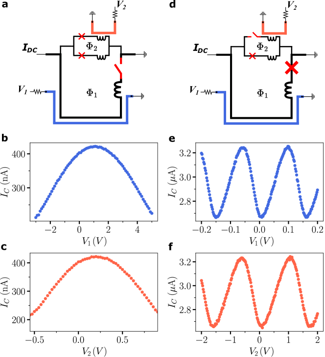
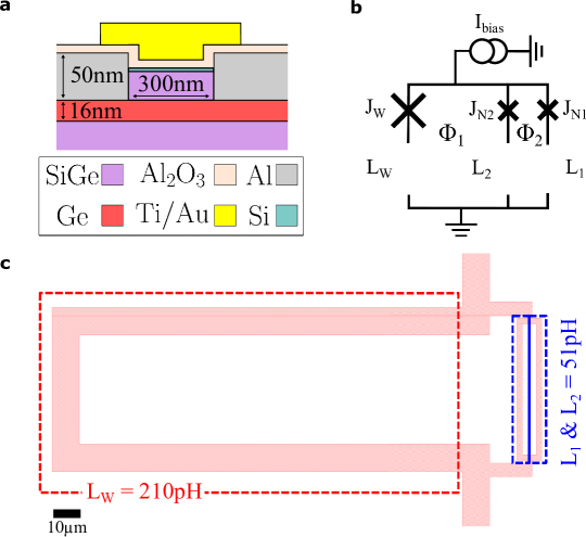
The G-SQUID (shown in Fig. 1a) consists of an aluminum superconducting loop with nearly symmetric arms embedding two nominally identical Josephson field-effect transistors (JoFETs) fabricated out of a SiGe/Ge/SiGe semiconductor heterostructure. The compressively strained Ge quantum well hosts a two-dimensional hole gas exhibiting a mobility of cm2/Vs measured at a carrier density of cm-2 . The two JoFETs and have a -wide and a -long Ge channel, see Supp. S1 for JoFETs details. The G-SQUID is embedded in a second larger loop together with a wider “reference” JoFET (-wide and -long Ge channel), enabling a direct CPR measurement [30, 20, 18, 31, 32, 33, 34, 35]. To this purpose, is designed to have a critical current much larger than those of and . The small and large loops are locally flux biased by two -wide and -thick Al lines whose crosstalks have been calibrated in-situ and than implicitly compensated throughout the rest of the paper (see Supp. S6).
Furthermore, we stress that the Al arms have small but non-negligible inductances, mostly of kinetic origin, that we label as , and . As our later analysis will reveal, it is in fact necessary to take these inductances into account to extract the intrinsic harmonic content of the JoFET CPRs from the measurements. In the rest of the paper, all theory curves are obtained from the circuit model shown in Fig. 1a (see Suppl. S2 for more details).
III characterisation of the individual JOFETs
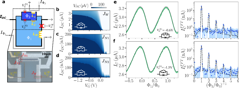
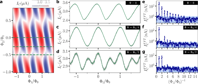
To access the individual DC transport characteristic of a given JoFET in such a parallel configuration, we purposely apply large positive gate voltages () to the other JoFETs, thereby suppressing current flow through their respective arms. The resulting individual characteristics of , and as a function of their respective gate voltages are shown on color scale in Figs. 1b-d, with the corresponding circuit measurement schematics displayed in the insets.
For all the JoFETs, the current at which the device switches from superconducting to normal state, close to the critical current , is clearly visible as an abrupt change of the measured source-drain voltage drop from to a finite value. A similar behavior is observed for the three JoFETs denoting consistent properties of the Ge channel and the superconducting contacts. In particular, we note that the two narrow JoFETs, designed to be identical, have very similar characteristics.
We now explore the flux dependence of the 2 narrow JoFET by measuring their CPR, shown in Fig. 1e,f alongside their corresponding Fourier transform, again using the pinched-off method to ensure single JoFET characterization (see schematics). In such measurement, the wide JoFET is used as a “reference” JoFET [30, 37] with much larger current at full accumulation, . The two JoFET gates voltages were tuned to equalize the first CPR harmonic in order of symmetrizing the G-SQUID ending up with and .
In total, 15 flux periods were measured to ensure sufficient resolution of the harmonics in Fourier space with each reported data point being the median value over 10 measurements with the light green area corresponds to standard deviation.
These measurements show that the flux response is skewed and composed of up to 5 distinguishable harmonics as a consequence of the JoFET’s high transparency, confirming the multi-harmonicity already observed on similar devices[29, 27].
The experimental demonstration of multi-harmonic JoFET being fulfilled, we now focus on the G-SQUID response and show how to engineer a sin(2) Josephson element.
IV sin(2) Josephson element
With the two JoFETs and independently characterized, we proceed to the measurement of the G-SQUID CPR, the main goal of this study. We remind that the wide JoFET is used as a reference JoFET while the two others, forming the G-SQUID, are kept in the symmetric regime described previously.
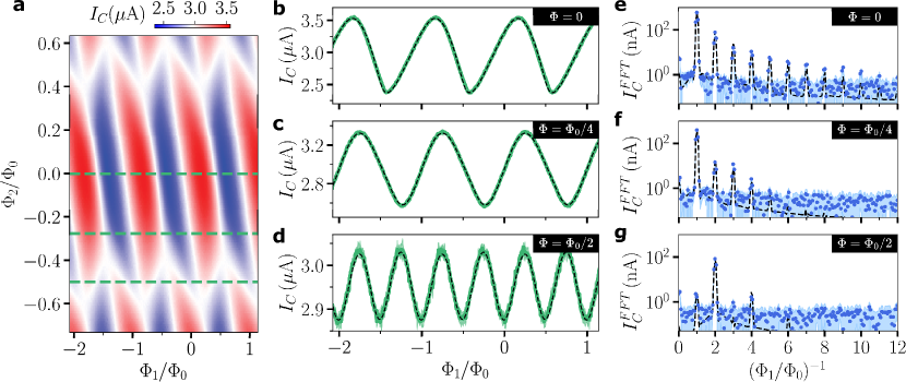
In Fig. 2a we show the G-SQUID critical current measured as a function of and (the flux threading the large and G-SQUID loops respectively) effectively revealing the flux tunability of the G-SQUID CPR. Remarkably the G-SQUID CPR linear phase evolution with respect to appeared in such a map as a tilted pattern, see Supp. S3 for deeper analysis.
We use the full dataset and fit it to the circuit model shown in Fig. 1a, (see Supp. S2 for details). From that procedure each JoFET harmonics are extracted. Here, only 3 harmonics per JoFET were enough to reproduce the data although higher harmonic’s were measured, while the 3 arms inductance were given from independent characterization (Supp. S1). We note that fitting the CPR double interference pattern, as a function of and , allows us to access with remarkable accuracy to all 3 harmonic amplitudes of each JoFET. In Fig. 2 and Fig. 3, the dashed lines systematically show the result of this model.
Through this model we learn that even with the current sample where the arm inductances of the G-SQUID, , is 20 times smaller than the JoFET Josephson inductances, , arm inductances enhance the amplitude of higher harmonics, with the enhancement becoming more pronounced as the harmonic order increases [35, 38]. Consequently, in individual JJs CPR measurements (Fig. 1e,f), arm inductances are responsible for a relative overestimation of harmonics amplitudes by +7, +22, +250 in junction for the , , and harmonics, respectively [39]. Our analysis clearly demonstrate that while higher harmonics are experimentally reached in multi-harmonic Josephson element, an extra care should be taken in the proper estimation of arm inductances to avoid crude overestimation of the reported harmonic amplitude. Finally, we remark that the presence of arms inductance leads to a shift of the CPR maximum from its expected 0 flux position [38].
In the following, we deepen our analysis by showing line cuts of the G-SQUID CPR for different fluxes and compare them to our model.
At (Fig 2b,e), there is no phase shift between and and thus the G-SQUID CPR should be the sum of the two JoFETs CPR (Fig. 1e,f). However the measured higher-order harmonics, above the 2nd one, are more pronounced than this expected sum. This phenomenon is fully captured by our model and attributed to the moderate ratio between the “reference” junction and the G-SQUID critical currents [37], at that particular flux.
At (Fig 2c,f), and are dephased by , resulting in destructive interference between even harmonics. Therefore the 2nd and 4th harmonics are reduced while the 1st and 3rd ones remain at the same magnitude. The resulting CPR is clearly less skewed than at . From our model, we conclude that the residual 2nd and 4th harmonics are again due to due a moderate ratio . Increasing the “reference” critical current by 10 would lead to a measured increased suppression of the 2nd harmonic by 10.
At (Fig 2d,g), a phase shift induces destructive interference between and odd harmonics, strongly suppressing the first and third harmonics. Consequently, we observe that the overall G-SQUID critical current is reduced and more importantly its flux periodicity is halved while the 2nd harmonic becomes the dominant one. In conclusion, at half flux quantum, our G-SQUID behaves as a Josephson element.
V Harmonic content analysis
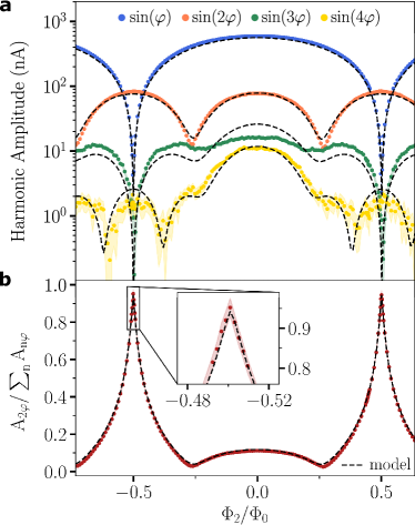
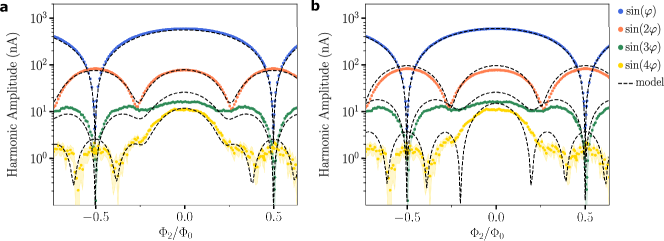
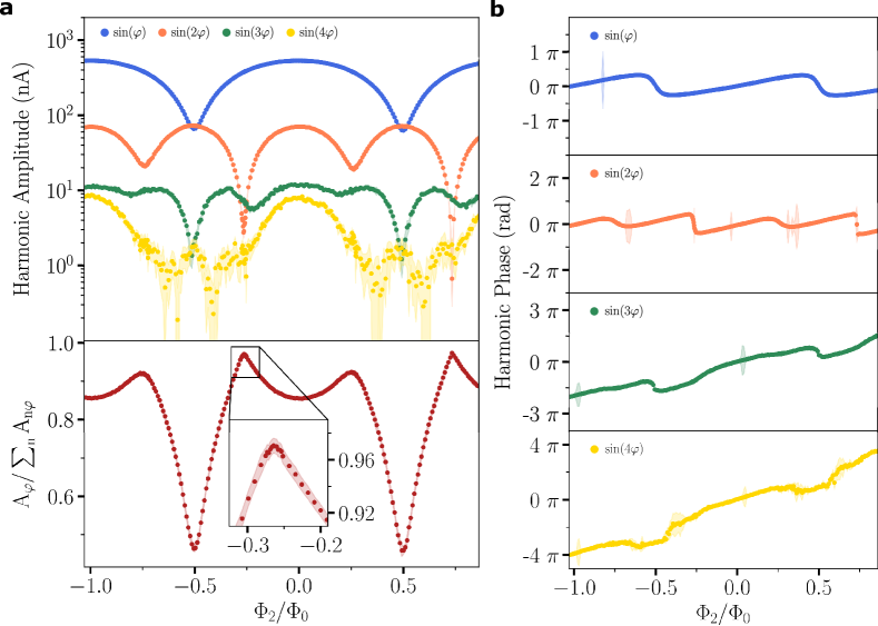
We now focus on the G-SQUID harmonics amplitude and show its full flux dependence in Fig. 3a. We present up to the 4th harmonics amplitude as colored dots with their associated uncertainty, , as shaded area of the same color. Furthermore, the harmonics extracted from the circuit model fitting procedure are also shown in dashed black line demonstrating a quantitative agreement with the data over 4 orders of magnitude. We recover the above statements at where all harmonics are maximized, at where the second harmonic shows a dip, while at , the first and third harmonics are strongly reduced.
We define the “purity” of the G-SQUID as the ratio of the second harmonic over the sum of all harmonics, , and show its flux dependence in Fig. 3b. Thus, at , we measure purity of .
At a flux , the contribution of the second harmonic goes down to . This reduction can be optimized by applying another gate configuration, which can result in a second harmonic purity going below (Supp. S5).
Our sample purity measurement was limited by the small ratio. From our model, we conclude that a 10 times larger ratio would have led to a measured purity up to .
We will now consider the main limitations to the realization of higher purity. First, the arm inductances induce an enhancement of the harmonic that is not suppressed at . Our model shows that a perfectly symmetric SQUID, with similar critical current amplitude, should have arm inductances lower than (instead of as in our G-SQUID) to reach a purity.
Second, the imperfect symmetry of the G-SQUID’s and harmonics prevents their complete cancellation by destructive interference. It is therefore necessary to maintain these asymmetries below (instead of as in our G-SQUID) in order to achieve a purity of .
With a view to realize a parity-protected qubit based on such a Josephson element, one may wish means to enter and exit the protected regime in order to perform qubit operations. We show here that the ratio between the second and first harmonics can be tuned by flux (Fig. 3) and gate voltage (Supp. 4). A flux shift allows to go from to in second harmonic purity. In Supp. 4 we show that a gate voltage shift on one of the two JoFETs permits to achieve a purity shift from to . Such values are compatible with the standard amplitude of a flux/gate voltage nanosecond pulse and would permit to exit the “protected” regime in a timescale comparable to a gate operation.
VI Conclusion
In summary, our work demonstrates an experimental realization of a Josephson element leveraging the intrinsic multi-harmonicity and gate tunability of SiGe-based proximitized Josephson junctions. We have developed a full circuit model that takes into account the non-sinusoidal CPR of every JoFETs and the arm inductances. We find that a decomposition of each CPR with only three harmonics is sufficient to reproduce the measurement although higher order’s are measured. As explained by the model, those are the result of a too small ratio . The “purity” of the charge-4e suppercurrent can reach and is highly gate and flux tunable offering a promising avenue for the realization of hybrid parity protected superconducting qubits [15, 14].
Acknowledgements.
This work has been supported by the ANR project SUNISIDEuP (ANR-19-CE47-0010), the PEPR ROBUSTSUPERQ and PRESQUILE (ANR-22-PETQ-0003), the ERC starting grant LONGSPIN (Horizon 2020 - 759388) and the Grenoble LaBEX LANEF. We thank the PTA (CEA-Grenoble) for the nanofabrication. We thank J. Renard and S. Messelot for their discussions.References
- Bravyi et al. [2022] S. Bravyi, O. Dial, J. M. Gambetta, D. Gil, and Z. Nazario, The future of quantum computing with superconducting qubits, Journal of Applied Physics 132, 160902 (2022), https://pubs.aip.org/aip/jap/article-pdf/doi/10.1063/5.0082975/19808793/160902_1_online.pdf .
- Acharya et al. [2023] R. Acharya, I. Aleiner, R. Allen, T. I. Andersen, M. Ansmann, F. Arute, K. Arya, A. Asfaw, J. Atalaya, R. Babbush, D. Bacon, J. C. Bardin, J. Basso, A. Bengtsson, S. Boixo, G. Bortoli, A. Bourassa, J. Bovaird, L. Brill, M. Broughton, B. B. Buckley, D. A. Buell, T. Burger, B. Burkett, N. Bushnell, Y. Chen, Z. Chen, B. Chiaro, J. Cogan, R. Collins, P. Conner, W. Courtney, A. L. Crook, B. Curtin, D. M. Debroy, A. Del Toro Barba, S. Demura, A. Dunsworth, D. Eppens, C. Erickson, L. Faoro, E. Farhi, R. Fatemi, L. Flores Burgos, E. Forati, A. G. Fowler, B. Foxen, W. Giang, C. Gidney, D. Gilboa, M. Giustina, A. Grajales Dau, J. A. Gross, S. Habegger, M. C. Hamilton, M. P. Harrigan, S. D. Harrington, O. Higgott, J. Hilton, M. Hoffmann, S. Hong, T. Huang, A. Huff, W. J. Huggins, L. B. Ioffe, S. V. Isakov, J. Iveland, E. Jeffrey, Z. Jiang, C. Jones, P. Juhas, D. Kafri, K. Kechedzhi, J. Kelly, T. Khattar, M. Khezri, M. Kieferová, S. Kim, A. Kitaev, P. V. Klimov, A. R. Klots, A. N. Korotkov, F. Kostritsa, J. M. Kreikebaum, D. Landhuis, P. Laptev, K.-M. Lau, L. Laws, J. Lee, K. Lee, B. J. Lester, A. Lill, W. Liu, A. Locharla, E. Lucero, F. D. Malone, J. Marshall, O. Martin, J. R. McClean, T. McCourt, M. McEwen, A. Megrant, B. Meurer Costa, X. Mi, K. C. Miao, M. Mohseni, S. Montazeri, A. Morvan, E. Mount, W. Mruczkiewicz, O. Naaman, M. Neeley, C. Neill, A. Nersisyan, H. Neven, M. Newman, J. H. Ng, A. Nguyen, M. Nguyen, M. Y. Niu, T. E. O’Brien, A. Opremcak, J. Platt, A. Petukhov, R. Potter, L. P. Pryadko, C. Quintana, P. Roushan, N. C. Rubin, N. Saei, D. Sank, K. Sankaragomathi, K. J. Satzinger, H. F. Schurkus, C. Schuster, M. J. Shearn, A. Shorter, V. Shvarts, J. Skruzny, V. Smelyanskiy, W. C. Smith, G. Sterling, D. Strain, M. Szalay, A. Torres, G. Vidal, B. Villalonga, C. Vollgraff Heidweiller, T. White, C. Xing, Z. J. Yao, P. Yeh, J. Yoo, G. Young, A. Zalcman, Y. Zhang, N. Zhu, and A. I. Google Quantum, Suppressing quantum errors by scaling a surface code logical qubit, Nature 614, 676 (2023).
- Douçot and Vidal [2002] B. Douçot and J. Vidal, Pairing of Cooper Pairs in a Fully Frustrated Josephson-Junction Chain, Physical Review Letters 88, 227005 (2002).
- Kitaev [2006] A. Kitaev, Protected qubit based on a superconducting current mirror, arXiv:cond-mat/0609441 (2006).
- Koch et al. [2007] J. Koch, T. M. Yu, J. Gambetta, A. A. Houck, D. I. Schuster, J. Majer, A. Blais, M. H. Devoret, S. M. Girvin, and R. J. Schoelkopf, Charge-insensitive qubit design derived from the Cooper pair box, Physical Review A 76, 042319 (2007).
- Manucharyan et al. [2009] V. E. Manucharyan, J. Koch, L. I. Glazman, and M. H. Devoret, Fluxonium: Single Cooper-Pair Circuit Free of Charge Offsets, Science 326, 113 (2009).
- Devoret and Schoelkopf [2013] M. H. Devoret and R. J. Schoelkopf, Superconducting Circuits for Quantum Information: An Outlook, Science 339, 1169 (2013).
- Kalashnikov et al. [2020] K. Kalashnikov, W. T. Hsieh, W. Zhang, W.-S. Lu, P. Kamenov, A. Di Paolo, A. Blais, M. E. Gershenson, and M. Bell, Bifluxon: Fluxon-Parity-Protected Superconducting Qubit, PRX Quantum 1, 010307 (2020).
- Gyenis et al. [2021] A. Gyenis, P. S. Mundada, A. Di Paolo, T. M. Hazard, X. You, D. I. Schuster, J. Koch, A. Blais, and A. A. Houck, Experimental Realization of a Protected Superconducting Circuit Derived from the 0 – Qubit, PRX Quantum 2, 010339 (2021).
- Ioffe and Feigel’man [2002] L. B. Ioffe and M. V. Feigel’man, Possible realization of an ideal quantum computer in Josephson junction array, Physical Review B 66, 224503 (2002).
- Gladchenko et al. [2009] S. Gladchenko, D. Olaya, E. Dupont-Ferrier, B. Douçot, L. B. Ioffe, and M. E. Gershenson, Superconducting nanocircuits for topologically protected qubits, Nature Physics 5, 48 (2009).
- Bell et al. [2014] M. T. Bell, J. Paramanandam, L. B. Ioffe, and M. E. Gershenson, Protected Josephson Rhombus Chains, Physical Review Letters 112, 167001 (2014).
- Smith et al. [2020] W. C. Smith, A. Kou, X. Xiao, U. Vool, and M. H. Devoret, Superconducting circuit protected by two-Cooper-pair tunneling, npj Quantum Information 6, 1 (2020).
- Larsen et al. [2020] T. W. Larsen, M. E. Gershenson, L. Casparis, A. Kringhøj, N. J. Pearson, R. P. G. McNeil, F. Kuemmeth, P. Krogstrup, K. D. Petersson, and C. M. Marcus, Parity-Protected Superconductor-Semiconductor Qubit, Physical Review Letters 125, 056801 (2020).
- Schrade et al. [2022] C. Schrade, C. M. Marcus, and A. Gyenis, Protected Hybrid Superconducting Qubit in an Array of Gate-Tunable Josephson Interferometers, PRX Quantum 3, 030303 (2022).
- Maiani et al. [2022] A. Maiani, M. Kjaergaard, and C. Schrade, Entangling Transmons with Low-Frequency Protected Superconducting Qubits, PRX Quantum 3, 030329 (2022).
- Smith et al. [2022] W. C. Smith, M. Villiers, A. Marquet, J. Palomo, M. R. Delbecq, T. Kontos, P. Campagne-Ibarcq, B. Douçot, and Z. Leghtas, Magnifying quantum phase fluctuations with Cooper-pair pairing, Physical Review X 12, 021002 (2022), arXiv:2010.15488 [cond-mat, physics:quant-ph] .
- Spanton et al. [2017] E. M. Spanton, M. Deng, S. Vaitiekėnas, P. Krogstrup, J. Nygård, C. M. Marcus, and K. A. Moler, Current–phase relations of few-mode InAs nanowire Josephson junctions, Nature Physics 13, 1177 (2017).
- English et al. [2016] C. D. English, D. R. Hamilton, C. Chialvo, I. C. Moraru, N. Mason, and D. J. Van Harlingen, Observation of nonsinusoidal current-phase relation in graphene Josephson junctions, Physical Review B 94, 115435 (2016).
- Golubov et al. [2004] A. A. Golubov, M. Y. Kupriyanov, and E. Il’ichev, The current-phase relation in Josephson junctions, Reviews of Modern Physics 76, 411 (2004).
- Beenakker [1992] C. W. J. Beenakker, Quantum transport in semiconductor-superconductor microjunctions, Physical Review B 46, 12841 (1992).
- Ueda et al. [2020] K. Ueda, S. Matsuo, H. Kamata, Y. Sato, Y. Takeshige, K. Li, L. Samuelson, H. Xu, and S. Tarucha, Evidence of half-integer Shapiro steps originated from nonsinusoidal current phase relation in a short ballistic InAs nanowire Josephson junction, Physical Review Research 2, 033435 (2020).
- Nichele et al. [2020] F. Nichele, E. Portolés, A. Fornieri, A. M. Whiticar, A. C. C. Drachmann, S. Gronin, T. Wang, G. C. Gardner, C. Thomas, A. T. Hatke, M. J. Manfra, and C. M. Marcus, Relating Andreev Bound States and Supercurrents in Hybrid Josephson Junctions, Physical Review Letters 124, 226801 (2020).
- Nanda et al. [2017] G. Nanda, J. L. Aguilera-Servin, P. Rakyta, A. Kormányos, R. Kleiner, D. Koelle, K. Watanabe, T. Taniguchi, L. M. K. Vandersypen, and S. Goswami, Current-Phase Relation of Ballistic Graphene Josephson Junctions, Nano Letters 17, 3396 (2017).
- Sochnikov et al. [2015] I. Sochnikov, L. Maier, C. A. Watson, J. R. Kirtley, C. Gould, G. Tkachov, E. M. Hankiewicz, C. Brüne, H. Buhmann, L. W. Molenkamp, and K. A. Moler, Nonsinusoidal Current-Phase Relationship in Josephson Junctions from the 3D Topological Insulator HgTe, Physical Review Letters 114, 066801 (2015).
- Portolés et al. [2022] E. Portolés, S. Iwakiri, G. Zheng, P. Rickhaus, T. Taniguchi, K. Watanabe, T. Ihn, K. Ensslin, and F. K. de Vries, A tunable monolithic SQUID in twisted bilayer graphene, Nature Nanotechnology 17, 1159 (2022).
- Valentini et al. [2024] M. Valentini, O. Sagi, L. Baghumyan, T. de Gijsel, J. Jung, S. Calcaterra, A. Ballabio, J. Aguilera Servin, K. Aggarwal, M. Janik, T. Adletzberger, R. Seoane Souto, M. Leijnse, J. Danon, C. Schrade, E. Bakkers, D. Chrastina, G. Isella, and G. Katsaros, Parity-conserving Cooper-pair transport and ideal superconducting diode in planar germanium, Nature Communications 15, 169 (2024).
- Ciaccia et al. [2024] C. Ciaccia, R. Haller, A. C. C. Drachmann, T. Lindemann, M. J. Manfra, C. Schrade, and C. Schönenberger, Charge-4e supercurrent in a two-dimensional InAs-Al superconductor-semiconductor heterostructure, Communications Physics 7, 1 (2024).
- Leblanc et al. [2023] A. Leblanc, C. Tangchingchai, Z. S. Momtaz, E. Kiyooka, J.-M. Hartmann, G. T. Fernandez-Bada, B. Brun-Barriere, V. Schmitt, S. Zihlmann, R. Maurand, É. Dumur, S. De Franceschi, and F. Lefloch, From nonreciprocal to charge-4e supercurrents in Ge-based Josephson devices with tunable harmonic content, arXiv:2311.15371 [cond-mat] (2023).
- Della Rocca et al. [2007] M. L. Della Rocca, M. Chauvin, B. Huard, H. Pothier, D. Esteve, and C. Urbina, Measurement of the Current-Phase Relation of Superconducting Atomic Contacts, Physical Review Letters 99, 127005 (2007).
- Murani et al. [2017] A. Murani, A. Kasumov, S. Sengupta, Y. A. Kasumov, V. T. Volkov, I. I. Khodos, F. Brisset, R. Delagrange, A. Chepelianskii, R. Deblock, H. Bouchiat, and S. Guéron, Ballistic edge states in Bismuth nanowires revealed by SQUID interferometry, Nature Communications 8, 15941 (2017).
- Stoutimore et al. [2018] M. J. A. Stoutimore, A. N. Rossolenko, V. V. Bolginov, V. A. Oboznov, A. Y. Rusanov, D. S. Baranov, N. Pugach, S. M. Frolov, V. V. Ryazanov, and D. J. Van Harlingen, Second-Harmonic Current-Phase Relation in Josephson Junctions with Ferromagnetic Barriers, Physical Review Letters 121, 177702 (2018).
- Endres et al. [2023] M. Endres, A. Kononov, H. S. Arachchige, J. Yan, D. Mandrus, K. Watanabe, T. Taniguchi, and C. Schönenberger, Current–Phase Relation of a WTe 2 Josephson Junction, Nano Letters 23, 4654 (2023).
- Frolov [2005] S. M. Frolov, Current-Phase Relations of Josephson Junctions with Ferromagnetic Barriers, Ph.D. thesis (2005).
- Ginzburg et al. [2018] L. V. Ginzburg, I. E. Batov, V. V. Bol’ginov, S. V. Egorov, V. I. Chichkov, A. E. Shchegolev, N. V. Klenov, I. I. Soloviev, S. V. Bakurskiy, and M. Y. Kupriyanov, Determination of the Current–Phase Relation in Josephson Junctions by Means of an Asymmetric Two-Junction SQUID, JETP Letters 107, 48 (2018).
- Hartmann et al. [2023] J.-M. Hartmann, N. Bernier, F. Pierre, J.-P. Barnes, V. Mazzocchi, J. Krawczyk, G. Lima, E. Kiyooka, and S. D. Franceschi, Epitaxy of Group-IV Semiconductors for Quantum Electronics, ECS Transactions 111, 53 (2023).
- Babich et al. [2023] I. Babich, A. Kudriashov, D. Baranov, and V. S. Stolyarov, Limitations of the Current–Phase Relation Measurements by an Asymmetric dc-SQUID, Nano Letters 23, 6713 (2023).
- Lecocq [2011] F. Lecocq, Dynamique Quantique Dans Un dcSQUID : Du Qubit de Phase à l’oscillateur Quantique Bidimensionnel, These de doctorat, Grenoble (2011).
- [39] From our model we conclude that the 4th harmonic is completely due to branch inductances, .
- Mattis and Bardeen [1958] D. C. Mattis and J. Bardeen, Theory of the Anomalous Skin Effect in Normal and Superconducting Metals, Physical Review 111, 412 (1958).
- Tinkham [2015] M. Tinkham, Introduction to Superconductivity, 2nd ed., Dover Books on Physics (Mineola, NY, 2015).
- Willsch et al. [2024] D. Willsch, D. Rieger, P. Winkel, M. Willsch, C. Dickel, J. Krause, Y. Ando, R. Lescanne, Z. Leghtas, N. T. Bronn, P. Deb, O. Lanes, Z. K. Minev, B. Dennig, S. Geisert, S. Günzler, S. Ihssen, P. Paluch, T. Reisinger, R. Hanna, J. H. Bae, P. Schüffelgen, D. Grützmacher, L. Buimaga-Iarinca, C. Morari, W. Wernsdorfer, D. P. DiVincenzo, K. Michielsen, G. Catelani, and I. M. Pop, Observation of Josephson harmonics in tunnel junctions, Nature Physics , 1 (2024).
Gate and flux tunable Josephson element in proximitized junctions
Supplemental Materials
S-I JoFET geometry and arm inductances
The inductances , and have a geometric and a kinetic contribution and . The kinetic inductance per square is estimated from the aluminum normal state sheet resistance and its superconducting critical temperature (booth measured on the same chip) [40, 41]:
| (S1) |
where is the Boltzmann constant. We find . To estimate the total loop inductance , we use a finite elements simulation performed in Sonnet and find while the inductance of the arm containing the wide junction is .
The SQUID loop inductance and the presence of higher harmonics in the junction CPR may both lead to skewness in the versus data.
S-II VS model with inductance
S-II.1 Theoretical model
To model the device behaviour we approximate the CPR of junction X (with ) by a sum of sinusoidal harmonics:
| (S2) |
where is the magnitude of the harmonic. We note , and the phases across each junction. Thus the overall current flowing through the device satisfy the following equation:
| (S3) |
Each arm of the double SQUID device contains an inductance (noted L1, L2 and L3) and the two loops are flux biased by fluxes and as depicted in Fig.S1. Consequently, the fluxoid quantification gives us the two following relations:
| (S4) |
| (S5) |
In order to get the critical current of the device, we have to find the maximum supercurrent for which there is a phase configuration that satisfy S3,4 and 5. Thus, to find this maximum, we add to our equation system:
| (S6) |
Therefore, we can numerically solve the equation system S3,4,5 and 6 and find the critical current of the entire device at any flux configuration , .
S-II.2 Fit to the model
We use this model to fit the G-SQUID flux response shown in Fig. 2a. The resulting fit harmonic composition is shown in Fig. S2a. The arm inductances are fixed to the values estimated in S1 and the harmonic composition given by the fit are reported in table S1. As a matter of comparison the same model with harmonic amplitudes fixed to the values measured in Fig. 1e,f is also shown in Fig. S2b.
| Parameter | |||||||||||||||
|---|---|---|---|---|---|---|---|---|---|---|---|---|---|---|---|
| Value | 210pH | 51pH | 51pH | 3.04µA | 174nA | 116nA | 0nA | 282.6nA | 31.8nA | 1.6nA | 0nA | 284.6nA | 32.0nA | 1.6nA | 0nA |
| Fit | fixed | fixed | fixed | free | free | free | free | free | free | free | free | free | free | free | free |
| Error | N/A | N/A | N/A | 0.03% | 3.18% | 1.14% | N/A | 0.02% | 0.18% | 3.51% | N/A | 0.02% | 0.18% | 3.48% | N/A |
| Parameter | ||||||||||||
|---|---|---|---|---|---|---|---|---|---|---|---|---|
| value | 210pH | 51pH | 51pH | 2.9µA | 303.2nA | 41nA | 5.6nA | 2.12nA | 302.9nA | 41.46nA | 5.5nA | 2.03nA |
| fit | fixed | fixed | fixed | fixed | fixed | fixed | fixed | fixed | fixed | fixed | fixed | fixed |
We notice here that the inclusion of arm inductances in the model while keeping the harmonic content measured in Fig. 1e,f is not sufficient to reproduce the data. However, by fitting the data with the model, one can find a set of parameter (ie. the harmonic content of each junction) that reproduce very well the experiment.
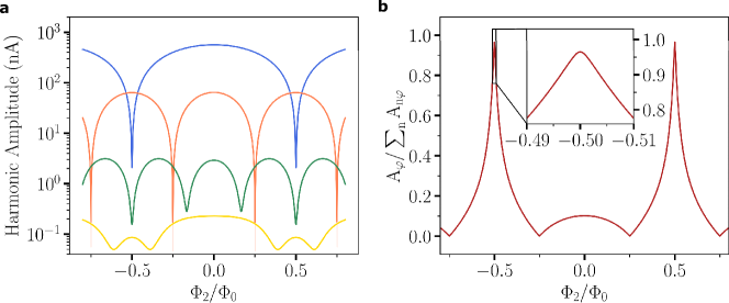
Furthermore, thanks to the fit, we now know the ”real” harmonic content of each junction thus we can estimate the theoretical harmonic content of the SQUID if there were no arm inductance. With a simple SQUID model without inductance we get the SQUID harmonic content shown in Fig. S3. This theoretical harmonic content is close to the one measured except that the fourth harmonic is much smaller. Thus, we conclude that, in this ideal situation, the purity, reaching , cannot be limited by the presence of a fourth harmonic not suppressed at . Hence, the remaining limiting parameter to reach the perfect regime is the SQUID symmetry, in particular the symmetry of the first and third harmonics.
It is worth noting that to accurately measure very high purity using a double SQUID device, one should care about the ratio between the reference junction and the SQUID critical currents. This ratio has to be large enough to prevent any artificial limitation on the figure of merit by enhancing higher order harmonics. This limitation can be illustrated by the SQUID CPR measured at and shown in Fig. 2b. This CPR exhibits sharp corners in the minima whereas the maxima are smooth thus breaking the time-reversal symmetry. This artefact is due to the mixing of the reference junction and SQUID CPRs that is made possible by a too small ratio when (see [37] for detailed analysis). However, this artefact disappear around the point of interest since for this flux.
S-III Harmonics phases
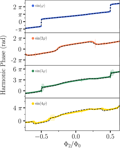
In the main text, the harmonics of the CPR are extracted by Fourier transformation and their respective absolute amplitudes are shown in Fig.3. Here, we show in Fig. S4 the phase of each harmonic as a function of the flux biasing the . Their behaviour are well reproduced by the model described in Supp. S2 and shown with black dotted lines. The flux threading the dictates the phase difference across the . Thus, at first approximation, the slope of the harmonic phase with respect to is:
| (S7) |
Furthermore, each time the harmonic is canceled (i.e. dips in Fig.3), its phase experience a shift.
S-IV Gate tuning of SQUID symmetry
We showed the flux dependency of the harmonic content of the symmetric SQUID CPR but another way to exit the ”” regime is to detune the SQUID from symmetry. For this experiment we set the flux through the SQUID to .
In a first instance, we set the gate voltage to to keep it a full accumulation and vary the gate voltage as shown in Fig. S5a. In Fig. S5b we identify the reduction of the first harmonic around . Therefore, this gates configuration corresponds to the symmetric SQUID regime. Fig. S5c shows the phase evolution of each harmonic of the SQUID CPR, even harmonics phases are steady while a shift occurs in odd phases around the symmetric regime point (see Supp. S4).
In a second instance, we study a configuration where the SQUID symmetry is more sensible to gate voltage. We fix and ramp between and as indicated in Fig. S5d. The harmonics gate dependency is here larger than in the previous gate configuration as shown in Fig. S5e. In such a configuration we show that a gate voltage shift on permits to achieve a purity shift from to .

S-V Second harmonic canceling
In the main text we focused on the cancelling of the first harmonic in order to engineer a CPR dominated by the second harmonic. To do so the gate configuration was chosen to equalize the first harmonics of the two junctions of the because the more symmetric they are the more they are cancelled out at . Here, we investigate the suppression of the second harmonic and choose a suitable gate configuration and . Fig. S6a shows the resulting CPR as function of . Line cuts and Fourier transforms (Fig. S6b,c,d,e,f,g) highlight the CPR at , and . We observe a complete suppression of the second harmonic at but we notice that the first harmonic is no longer completely canceled at . This is due to the fact that we cannot reach perfect symmetry in the for booth first and second harmonics.
Fig. S7 shows the amplitudes and phases of each harmonics with respect to the flux threading the SQUID. The lower panel of Fig. S7a shows the first harmonic purity defined as ratio between the first harmonic amplitude and the total supercurrent amplitude. Its maximum value reported is . It is worth to notice that this range of purity is comparable to state of the art aluminium tunnel junctions as recently reported by Willsch et al. [42].
S-VI Flux compensation
Two local flux lines permits to independently flux bias the flux loops. The two flux lines are current biased at with a resistor as depicted in Fig. S8a,d. In order to estimate the cross-talk between the two fluxes we conduct two experiments. First, the small SQUID is isolated by pinching off () and the SQUID oscillations are measured by threading with (Fig. S8b) and with (Fig. S8c). Secondly, is pinched off to isolate an asymmetric SQUID composed of and . Again, SQUID oscillations are measured by threading the loop with (Fig. S8e) and (Fig. S8f).
By superposing, Fig. S8b with Fig. S8c and Fig. S8e with Fig. S8f we deduce the following compensation matrix: