Mathematical model of fluid front dynamics driven by porous media pumps
Abstract
Air-permeable porous media hosts air within their pores. Upon removal from the material’s interior, these porous media have the tendency to replenish the air, effectively acting as a suction pump. Therefore, the technique used to convert a porous media into a pump, consists of degassing the material to remove their air inside. The suction property when recovering the air, can be used to move a liquid through a microfluidic channel, studying the dynamics of the liquid-air front. In this article, we have developed a theoretical mathematical model that precisely characterize the behavior of this kind of pumps and the dynamics of the liquid-air front. This model allows us to use porous media pumps as very accurate devices to move liquids in a completely controlled way, being able to obtain characteristic properties of fluids such as viscosity or the pressure applied to them. We have tested it using experimental data from the literature, and we have been able to observe that the theory fits satisfactorily with the experiments, being able to affirm that the model is correctly satisfied. This type of pump is of great interest to the scientific community because of its small size and the fact that it operates without any external power source.
I INTRODUCTION
The study and development of self-powered micropumps at the microscale is an area of interest nowadays due to its important applications, such as autonomous microsystems and and the power that they showcase despite their small size, making this type of pump completely portable. When placed in a microfluidic system, these micropumps produce a pressure difference inside of the channel capable of moving a fluid without any bulky external power source Xu et al. (2020).
There are many self-powered autonomous pumps developed through various approaches and for different purposes Park and Park (2019); Srisomwat et al. (2020); Guler et al. (2018), which can be required for many microfluidic applications. For instance, the development of a macroscale chemostat for E. coli population control studying an artificial microbial ecosystem Balagaddé et al. (2005); Nagy et al. (2018), cancer monitoring Tokuoka et al. (2021); Van Midwoud et al. (2010), real-time changes in gene expression in budding yeast Charvin, Oikonomou, and Cross (2009), the measurement of the response over time of cellular lines to the administration of drug-containing media Grist et al. (2019); Gencturk et al. (2020), among other important applications Vaccaro et al. (2017); Porta, Benaglia, and Puglisi (2016); Lummiss et al. (2017); Folgueiras-Amador et al. (2017); Mashaghi et al. (2016); Zhang and Sun (2021); Ripoll et al. (2022); Eichler, Klages, and Lachmann (2016); Uh et al. (2017); Team (2021).
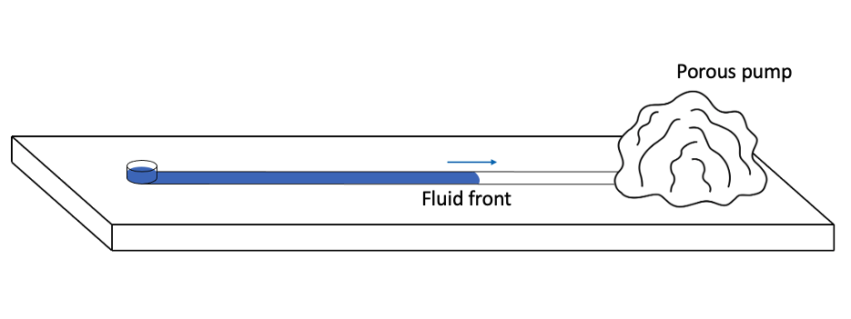
The most promising type of pump that meets the requirements of being small, self-contained, portable and capable of pulling liquids for long periods of time are porous media pumps. Which are composed of an air-permeable porous mediaXu et al. (2020); Park and Park (2019). These materials possess air within their internal structure. When degassing the material in a vacuum chamber, it loses a fraction of the volume of air it contained. Once it is placed at atmospheric pressure, it recovers the air it loss from the outside. Depending on the properties of the pore, it will take more or less time to recover this air. When the material is placed at the outlet of a microfluidic system, the recovered air creates a pressure gradient capable of moving a fluidEtxebarria-Elezgarai et al. (2020); Woo et al. (2021).
Any air-permeable porous medium can be used to create a porous medium pump. However, for air reabsorption not to occur virtually instantaneously, the pores of the medium must be small enough to allow prolonged air diffusion over time. The most common material for this purpose is polydimethylsiloxane (PDMS)Etxebarria-Elezgarai et al. (2020); Woo et al. (2021); Xu et al. (2020); Alvarez-Braña et al. . However, it is not the only one, as there are countless other materials that have the same characteristics, such as some 3D printing resinsAlvarez-Braña et al. (2021).
Although empirical equations describing the behavior of this type of pumps are proposed in the literatureWoo et al. (2021); Xu et al. (2020), there is no rigorous physical model that accurately describes theoretically the operation of this type of pumps, nor the behaviour of a liquid inside a microchannel moved by a porous media pump, until now.
In the present article, using the theory of fluid dynamics, we derive theoretically a mathematical description to predict, in a rigorous way, the behavior of the air-fluid front in the microfluidic system moved by these kind of pumps.
The proposed mathematical model allows us to know the dynamics of the front as a function of the intrinsic characteristics of the pump, the fluid properties and the geometry of the microfluidic system. Thus, using this model, we would be able to determine fluid properties, such as its viscosity, and the relevant pump characteristics, such as the pressure it exerts on the fluid or the air volume that the pump is capable to absorb after the degassing process.
As said above, a porous media pump that has been degassed will absorb air from the atmosphere. However, it will absorb air from all their surfaces. Thus, when one of the surfaces is placed in contact with a fluid channel containing a liquid that generates resistance to flow, the pump will not absorb air equally over its entire surface, but will tend to absorb it where it is easier, i.e., due to the resistance of the fluid, the pump will absorb more air on the surface that is not in contact with the channel, reducing the performance of the pump.
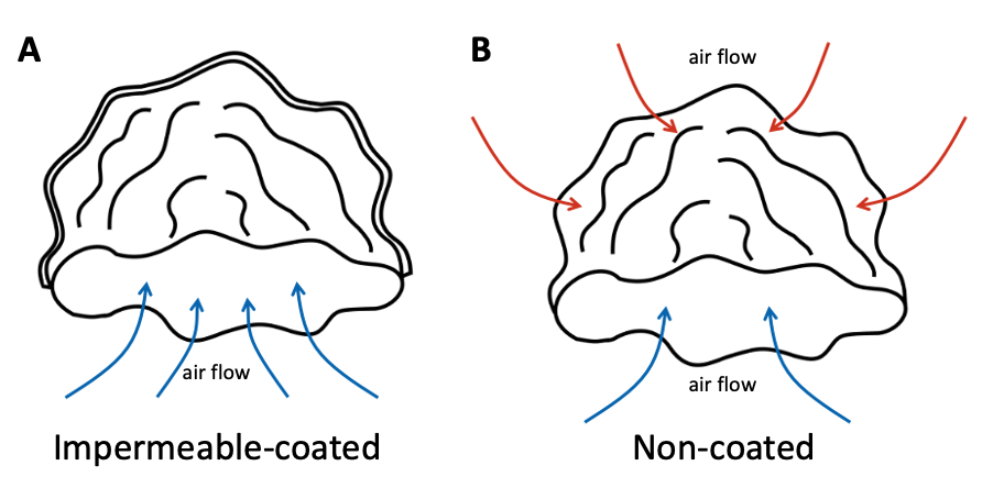
This has led some researchersAlvarez-Braña et al. ; Xu et al. (2020) to cover the pump faces that are not in contact with the channel with an air-impermeable material, so that all air reabsorption occurs through the microfluidic channel.
In this article, a theoretical mathematical model has been found for each one of the cases, for non-coated pumps and for impermeable-coated pumps.
II MATHEMATICAL MODEL
As mentioned, this study theoretically describes two types of porous media pumps: those with all external surfaces covered with an impermeable material, which do not generate pressure losses and only absorb air from the channel. And non-covered pumps, which experience pressure losses from their external surfaces. Therefore, we present two different mathematical models, one for each of the cases.
II.1 Front flow dynamics on impermeable-coated porous media pumps
When studying the behavior of the fluid in the channel pulled by the pump suction, we must take into account the pressure generated by the pump.
The pump initiates its suction power due to lack of air inside. As it sucks air, it becomes to fill. Then, the pump reduces its suction power until it reaches the equilibrium point when it is completely filled with air, as it was before the degassing process. At that time, the pressure will be zero. This behavior causes the pressure exerted by the pump on the channel to decrease as a function of time from an initial value to zero (when the front stops). We assumed that the time-dependent pressure of the pump obeys the decay law equation, where the pressure is measured with respect to the atmospheric pressure Woo et al. (2021).
| (1) |
Where is a characteristic temporal scale. Solving the differential equation (1), we obtained the following expression for the pressure:
| (2) |
Where is the maximum pressure, that is, the initial pressure generated by the pump.
The front position () can be calculate using Darcy’s equation (3), considering that all the pressure exerted by the pump is acting completely inside the microchannel, since impermeable-covered pumps do not generate pressure losses due to their external coated surfaces.
| (3) |
Where is the velocity of the front, is the viscosity of the fluid and the height of the channel. Solving the differential equation (3) for the front position using the expression for given by equation (2), we obtained the following equation (4):
| (4) |
Were is the maximum value of the front position (the long-time position), that it is given by the following expression:
| (5) |
Equation (4), which has been derived mathematically, coincide with the expression found in the literatureAlvarez-Braña et al. . Additionally, we found an expression for the long-time position of the advancing front () in terms of the initial pressure (), the geometry of the system () and the viscosity of the fluid sample () in equation (5).
Taking into account that all the volume removed from the pump in the degassing process, in the case of pumps with a sealed external surface, is recovered by the microfluidic channel, we can know the volume of liquid entering the channel as a function of time. This value will coincide with the volume of air entering the pump as a function of time if the suction speed is sufficiently slow to avoid air compressibility effects. Thus, assuming a channel of constant cross section (, where is the width of the channel) we obtain that the volume of liquid in the channel is:
| (6) |
Where is the air removed from the pump in the degassing process, given for the expression:
| (7) |
This volume is gradually recovered when the pump is placed at atmospheric pressure, leading to the front advancement. Then, the value depends on the degassing time, the degassing pressure and the surface area of the pump. As said above, this volume of air is equivalent to the volume of liquid displaced inside the channel at large times.
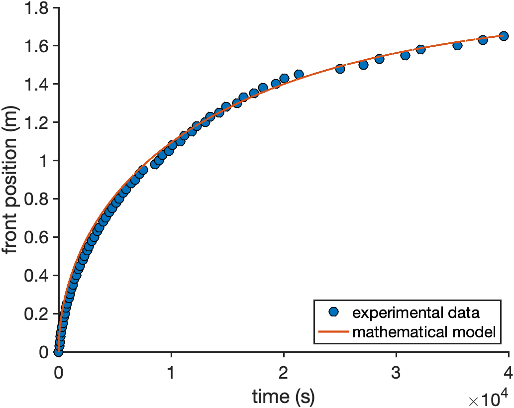
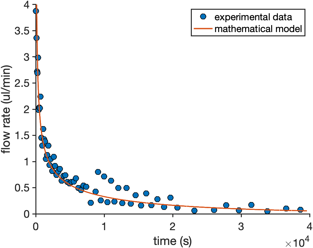
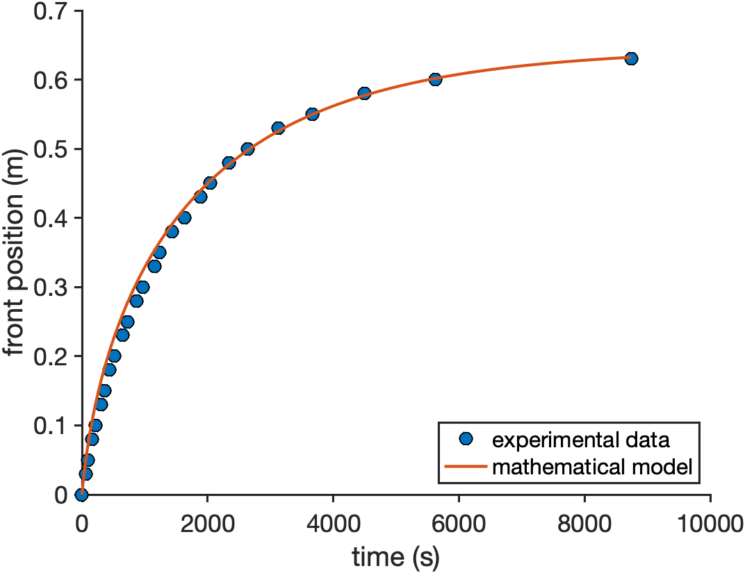
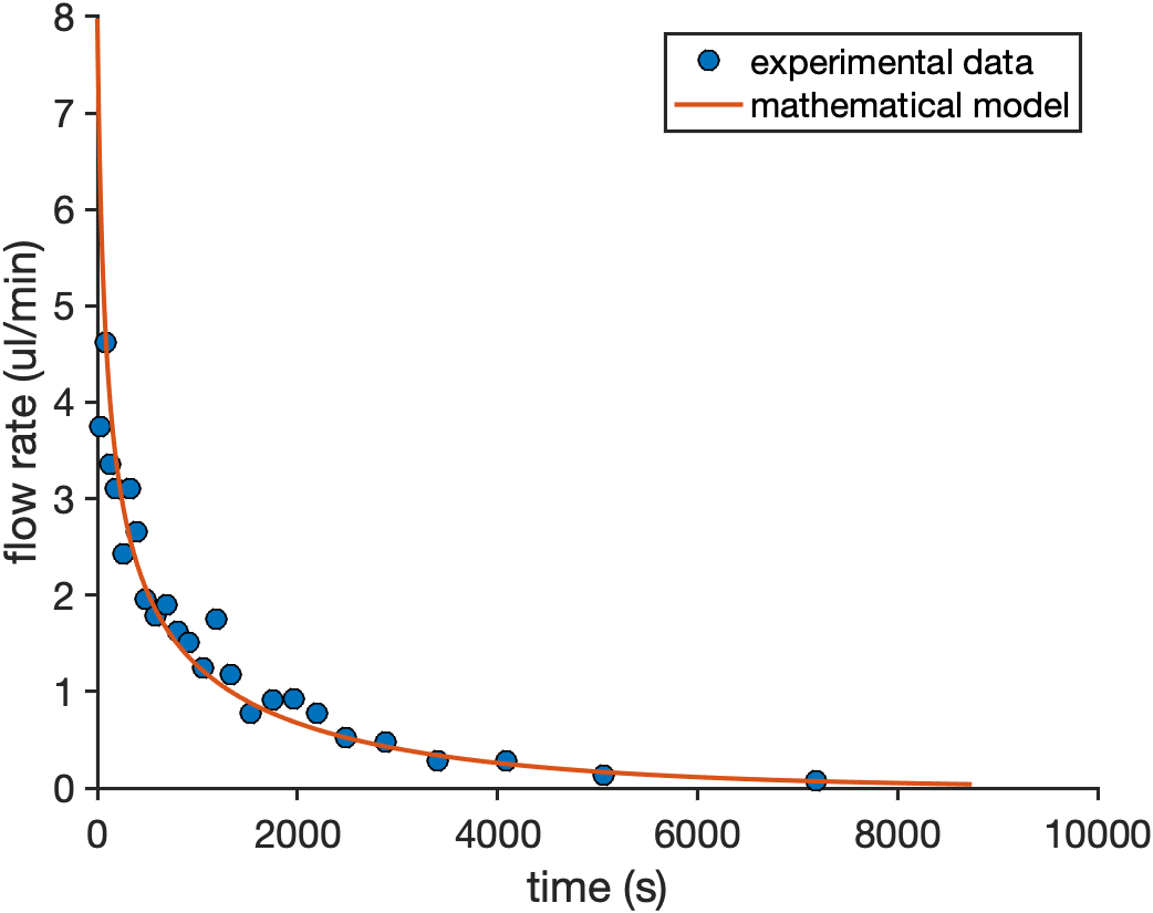
Figures 3 and 4 show the curves given by equations (4) and (8). The experimental data shown in those figures, is obtained from experiments of referenceAlvarez-Braña et al. and is used to validate the mathematical model proposed in this article. The experimental pumps they use, are porous PDMS pumps with their external surfaces coated by an impermeable epoxy resin. Although in figures 3 and 4 we just show the experimental data and the mathematical model of one type of pump (effective surface of 683 mm2 and a degassing time of 30min), the validation was performed using all available data in referenceAlvarez-Braña et al. . In all cases, the model fits correctly with experimental results for this type of pumps.
The long-time position () of the experimental data we have was measured experimentally. Then, the parameter was fitted from experimental results of the position given by equation (5). Once the parameter is calculated, equation (5) could be used to determine the initial preassure in terms of the long therm position and the temporal parameter .
Woo et al. Woo et al. (2021) presented an expression to calculate the parameter for PDMS porous pumps by using a diffusion model: , where is the total surface area of the pump, is the PDMS bulk volume of the pump, is the diffusion coefficient of air in PDMS () and is a characteristic length of air diffusion in PDMS (). This expression corresponds, in terms of magnitude, to the value determined using the model presented in this article.
From equation (5) the expression for the viscosity is:
| (9) |
Therefore, using epoxy-coated pumps, this system allows both the characterization of different parameters of the pumps and the obtention of the viscosity of liquids inside the microchannel by measuring experimentally and and using the initial value of the pressure .
As the volume of air extracted from the pump () is given by the degassing process, the pressure exerted by the pump in a given channel will depend on this volume () and the geometry of the channel.
II.2 Front flow dynamics on non-coated porous media pumps
If a porous media pump is non-coated, it is capable of absorbing air across its entire surface. When placed over a channel, only a fraction of the surface of the pump is exposed to this channel ( or effective surface area). Therefore, in this case, the time dependent pressure in the micro-channel is also given by equation (2), but adding a pressure loss term due to their non-covered external sides:
| (10) |
The pressure loss () is proportional to the flow rate of air that comes inside the pump, consequently it is proportional to the front velocity of the fluid inside of the channel:
| (11) |
Where is a loss constant which informs us of the amount of volume absorbed by the non-effective surface of the pump. Or, in other words, the pressure loss in the channel due to this surface.
Solving Darcy’s equation (3) using the pressure of equations (10) and (11) we obtained the following expression for the front position:
| (12) |
Isolating the position, we have:
| (13) |
Knowing where the front stops (that ), the value of the loss constant () could be calculated:
| (14) |
Notice that equations (13) and (14) coincides with equations (4) and (5), respectively, when considering . This result refines this model and makes equation (13) the most general equation for the front position of all porous media pumps.
Once we determine the front position of the liquid inside the channel (equation (13)), we can calculate the volume of liquid entering the channel. This volume corresponds to the volume of air sucked by the pump from its effective surface:
| (15) |
With this equation, we can determine the volume of air that the pump will recover from its effective surface (): .
The volume recovered from the effective surface, in this case, do not correspond with the total volume removed from the pump () as it did in the impermeable-coated case. In this type of pumps, a volume is also removed during the degassing process and it also depends on the same parameters as the previous case. So, the total volume removed from the pump will correspond to the volume of liquid it would absorb if it had an impermeable coating on their external surface. With this understanding, we can affirm that the total air volume removed from the pump will follow equation (7).
Knowing the total amount of air removed from the pump () and the volume absorbed from the effective surface (), we can define the volume of air absorbed from the external surface of the pump as the difference between the total volume removed from the pump and the volume abserbed from the effective surface ():
| (16) |
To obtain the expression for the fluid flow for this case, we must derive equation (15).
| (17) |
Using equation (13), by performing a power series development of the square root we obtained the following equation:
| (18) |
In this case, the long-time position was reduced to:
| (19) |
This approximation is always valid as long as the loss parameter () became sufficiently large, i.e., the volume absorbed by the external surfaces exceeds the volume absorbed from the effective surface. However, if the air absorbed by the external surface and the one absorbed by the effective surface are of the same order, the approximation is no valid.
Expression (18) coincides with the experimental results for non-coated PDMS pumps obtained in literatureAlvarez-Braña et al. ; Woo et al. (2021) .
Figures 5 and 6 compere the curves given by equations (13) and (17) with the experimental data obtained from experiments of referenceAlvarez-Braña et al. , which was used to validate the model. In this case, the experimental pumps utilized are porous PDMS pumps without any coating, allowing air absorption from their external surfaces. As in the previous case, figures 5 and 6 only show one type of pump (the same one as before but without epoxy-resin coating). However, the validation of the model was made for all data available in referenceAlvarez-Braña et al. and, as in the previous case, the mathematical prediction agrees accurately with the experimental points in all cases.
Notice that the pressure obtained for a non-coated pump is higher than in the impermeable-coated case if both pumps are degassed the same time, but the long-term final position is much lower. This is because, in the case of the coated pumps, the effective surface area for the degassing process is much smaller (external surface were impermeable-coated before degassing). Therefore, for an impermeable-coated pump, the air is only removed trough the effective surface, while in the non-coated one, it is absorbed from all its surface. This difference causes a much larger volume of air to be extracted from a non-coated pump than from an epoxy-coated pump for the same degassing time. As a result, a much larger initial pressure is obtained for the non-coated pumps. In addition, although the initial pressure of non-coated pumps is higher, the final front position of the fluid is smaller due to the air loss through the external surfaces.
III CONCLUSIONS
In this article, a mathematical model based in fluid dynamics, that correctly describes the behavior of a liquid inside a channel moved by self-powered porous media pumps, has been presented. This model allows to use porous media pumps in the field of microfluidics, knowing with precision the behaviour of the liquid that it moves.
When the external surface of a porous media pump is coated with an air-impermeable material, it does not generate pressure losses through this surface. Then, the pressure exerted by these pumps inside the channel was described by a decay law equation and the front position was derived from Darcy’s equation, resulting in an exponential growth with a square root (Eq. 4). As a result, the mathematical model allows us to obtain an expression for the maximum position () or the volume it is capable to absorb (). Both expressions depend on the initial pressure of the pump (), the geometry of the system () and the fluid viscosity (). Furthermore, using this model, we would be able to calculate the viscosity of any fluid within the microchannel by experimentally measuring the final front position (), the characteristic times of the pump ( value) and the characteristic initial pressure of the pump ().
On the other hand, when the pump is non-impermeable coated, pressure losses occur through their external surfaces. This pressure losses have the same time dependence as the front velocity, since they are proportional to the flow rate exerted by the pump. Thus, we introduce a parameter () that quantifies the losses due to their external surface. In order to obtain the mathematical model for these autonomous systems connected to non-coated pumps, Darcy’s equation was solved considering these pressure losses. With the solution of the equation, we obtain an expression for the front position (Eq. 13), which depends on the initial pressure of the pump (), the geometry of the system (), the fluid viscosity () and the loss constant (). The volume absorbed by the pump from the channel and from their external surfaces over time has also been presented. In addition, an equation for the position of non-coated pumps can be simplified using a Taylor expansion. This simplification is a highly accurate approximation when the losses from the external surface are significant. This approximation simplifies the expression into an exponential rise obtained by other authors. When this approximation is fulfilled, the maximum position of the front does not depend on the fluid viscosity.
In conclusion, this paper demonstrates the effectiveness of mathematical models in characterizing porous media pumps for flow control in long-term autonomous microsystems.
Acknowledgements.
We acknowledge financial support from “Red Temática MIFLUNET”.AB-C and AH-M acknowledge support from “Ministerio de Ciencia e Innovación” (Spain) under project PID2022-137994NB-100 and “AGAUR” (Generalitat de Catalunya) under project 2021 SGR 00450.
YA-B, FB-L and LB-D acknowledge funding support from “Ministerio de Ciencia y Educación de España” under grant PID2020-120313GB-I00/AIE/10.13039/501100011033 and from Basque Government under “Grupos Consolidados” with Grant No. IT1633-22.
References
- Xu et al. (2020) L. Xu, A. Wang, X. Li, and K. W. Oh, “Passive micropumping in microfluidics for point-of-care testing,” Biomicrofluidics 14, 031503 (2020).
- Park and Park (2019) J. Park and J.-K. Park, “Integrated microfluidic pumps and valves operated by finger actuation,” Lab on a Chip 19, 2973–2977 (2019).
- Srisomwat et al. (2020) C. Srisomwat, P. Teengam, N. Chuaypen, P. Tangkijvanich, T. Vilaivan, and O. Chailapakul, “Pop-up paper electrochemical device for label-free hepatitis b virus dna detection,” Sensors and Actuators B: Chemical 316, 128077 (2020).
- Guler et al. (2018) M. T. Guler, Z. Isiksacan, M. Serhatlioglu, and C. Elbuken, “Self-powered disposable prothrombin time measurement device with an integrated effervescent pump,” Sensors and Actuators B: Chemical 273, 350–357 (2018).
- Balagaddé et al. (2005) F. K. Balagaddé, L. You, C. L. Hansen, F. H. Arnold, and S. R. Quake, “Long-term monitoring of bacteria undergoing programmed population control in a microchemostat,” Science 309, 137–140 (2005).
- Nagy et al. (2018) K. Nagy, Á. Ábrahám, J. E. Keymer, and P. Galajda, “Application of microfluidics in experimental ecology: the importance of being spatial,” Frontiers in microbiology 9, 496 (2018).
- Tokuoka et al. (2021) Y. Tokuoka, K. Kondo, N. Nakaigawa, and T. Ishida, “Development of a microfluidic device to form a long chemical gradient in a tissue from both ends with an analysis of its appearance and content,” Micromachines 12, 1482 (2021).
- Van Midwoud et al. (2010) P. M. Van Midwoud, G. M. Groothuis, M. T. Merema, and E. Verpoorte, “Microfluidic biochip for the perifusion of precision-cut rat liver slices for metabolism and toxicology studies,” Biotechnology and bioengineering 105, 184–194 (2010).
- Charvin, Oikonomou, and Cross (2009) G. Charvin, C. Oikonomou, and F. Cross, “Long-term imaging in microfluidic devices,” in Live Cell Imaging: Methods and Protocols (Springer, 2009) pp. 229–242.
- Grist et al. (2019) S. M. Grist, S. S. Nasseri, L. Laplatine, J. C. Schmok, D. Yao, J. Hua, L. Chrostowski, and K. C. Cheung, “Long-term monitoring in a microfluidic system to study tumour spheroid response to chronic and cycling hypoxia,” Scientific Reports 9, 17782 (2019).
- Gencturk et al. (2020) E. Gencturk, E. Yurdakul, A. Y. Celik, S. Mutlu, and K. O. Ulgen, “Cell trapping microfluidic chip made of cyclo olefin polymer enabling two concurrent cell biology experiments with long term durability,” Biomedical Microdevices 22, 1–12 (2020).
- Vaccaro et al. (2017) L. Vaccaro, C. Petrucci, V. Kozell, and E. Ballerini, “Flow tools to define waste/time/energy-minimized protocols,” Sustainable Flow Chemistry: Methods and Applications , 165–192 (2017).
- Porta, Benaglia, and Puglisi (2016) R. Porta, M. Benaglia, and A. Puglisi, “Flow chemistry: recent developments in the synthesis of pharmaceutical products,” Organic Process Research & Development 20, 2–25 (2016).
- Lummiss et al. (2017) J. A. Lummiss, P. D. Morse, R. L. Beingessner, and T. F. Jamison, “Towards more efficient, greener syntheses through flow chemistry,” The Chemical Record 17, 667–680 (2017).
- Folgueiras-Amador et al. (2017) A. A. Folgueiras-Amador, K. Philipps, S. Guilbaud, J. Poelakker, and T. Wirth, “An easy-to-machine electrochemical flow microreactor: Efficient synthesis of isoindolinone and flow functionalization,” Angewandte Chemie International Edition 56, 15446–15450 (2017).
- Mashaghi et al. (2016) S. Mashaghi, A. Abbaspourrad, D. A. Weitz, and A. M. van Oijen, “Droplet microfluidics: A tool for biology, chemistry and nanotechnology,” TrAC Trends in Analytical Chemistry 82, 118–125 (2016).
- Zhang and Sun (2021) G. Zhang and J. Sun, “Lipid in chips: a brief review of liposomes formation by microfluidics,” International journal of nanomedicine 16, 7391 (2021).
- Ripoll et al. (2022) M. Ripoll, E. Martin, M. Enot, O. Robbe, C. Rapisarda, M.-C. Nicolai, A. Deliot, P. Tabeling, J.-R. Authelin, M. Nakach, et al., “Optimal self-assembly of lipid nanoparticles (lnp) in a ring micromixer,” Scientific Reports 12, 9483 (2022).
- Eichler, Klages, and Lachmann (2016) M. Eichler, C.-P. Klages, and K. Lachmann, “Surface functionalization of microfluidic devices,” Microsystems for Pharmatechnology: Manipulation of Fluids, Particles, Droplets, and Cells , 59–97 (2016).
- Uh et al. (2017) M. Uh, J.-S. Kim, J.-H. Park, D. H. Jeong, H.-Y. Lee, S.-M. Lee, and S.-K. Lee, “Fabrication of localized surface plasmon resonance sensor based on optical fiber and micro fluidic channel,” Journal of Nanoscience and Nanotechnology 17, 1083–1091 (2017).
- Team (2021) E. Team, “Microreactors & microfluidics in chemistry–a review,” Elveflow (2021).
- Etxebarria-Elezgarai et al. (2020) J. Etxebarria-Elezgarai, Y. Alvarez-Braña, R. Garoz-Sanchez, F. Benito-Lopez, and L. Basabe-Desmonts, “Large-volume self-powered disposable microfluidics by the integration of modular polymer micropumps with plastic microfluidic cartridges,” Industrial & Engineering Chemistry Research 59, 22485–22491 (2020).
- Woo et al. (2021) S. O. Woo, M. Oh, K. Nietfeld, B. Boehler, and Y. Choi, “Molecular diffusion analysis of dynamic blood flow and plasma separation driven by self-powered microfluidic devices,” Biomicrofluidics 15, 034106 (2021).
- (24) Y. Alvarez-Braña, A. Benavent-Claro, F. Benito-Lopez, A. Hernandez-Machado, and L. Basabe-Desmonts, “Microfluidic front dynamic experiments for the characterization of pumps for long-term autonomous microsystems,” .
- Alvarez-Braña et al. (2021) Y. Alvarez-Braña, J. Etxebarria-Elezgarai, L. R. de Larrinaga-Vicente, F. Benito-Lopez, and L. Basabe-Desmonts, “Modular micropumps fabricated by 3d printed technologies for polymeric microfluidic device applications,” Sensors and Actuators B: Chemical 342, 129991 (2021).
- Hosokawa et al. (2004) K. Hosokawa, K. Sato, N. Ichikawa, and M. Maeda, “Power-free poly (dimethylsiloxane) microfluidic devices for gold nanoparticle-based dna analysis,” Lab on a Chip 4, 181–185 (2004).