Suppression of the Skyrmion Hall Effect in Synthetic Ferrimagnets with Gradient Magnetization
Abstract
Magnetic skyrmions are promising building blocks for future spintronic devices. However, the skyrmion Hall effect (SkHE) remains an obstacle for practical applications based on the in-line transport of skyrmions. Here, we numerically study the static properties and current-driven dynamics of synthetic ferrimagnetic skyrmions. Inspired by graded-index magnonics, we introduce a linear gradient of saturation magnetization () in the skyrmion-hosting sample, which effectively modulates the skyrmion Hall angle and suppresses the SkHE. Micromagnetic simulations reveal that ferrimagnetic skyrmions could exhibit greater susceptibility to the variation of as compared to their ferromagnetic counterparts. The Thiele analysis is also applied to support the simulation results, which elucidates that the gradient dynamically modifies the intrinsic normalized size of skyrmions, consequently impacting the SkHE. Our results pave the way to the graded-index skyrmionics, which offers novel insights for designing ferrimagnet-based skyrmionic devices.
I Introduction
Magnetic skyrmions are topologically nontrivial spin textures [1, 2, 3, 4, 5] characterized by an integer topological charge number [2], and hold great potential as nonvolatile information carriers in next-generation classical and quantum spintronic devices [6, 7, 8, 9, 10, 11, 12, 13, 14, 15, 16, 17, 18]. Although the skyrmionics field has predominantly focused on skyrmions in ferromagnetic (FM) materials since their initial experimental observation [19], challenges may arise from the skyrmion Hall effect (SkHE) when driving FM skyrmions by spin currents [20, 21, 22, 23, 24, 25, 26]. This effect leads to a transverse motion due to the -dependent Magnus force [2], often resulting in undesired accumulation and annihilation of skyrmions at device edges [27, 28]. A promising avenue to avoid the SkHE involves the use of antiferromagnetic (AFM) skyrmions [29, 30, 31, 32, 33, 34, 35, 36, 37, 38, 39, 40, 41, 42, 43, 44, 45, 46, 47]. While AFM skyrmions exhibit diminished SkHE [32] and potential for fast spin dynamics [48], their insensitivity to external stimuli, such as the magnetic field, limits the manipulation and detection [49].
A balanced solution is to construct the ferrimagnetic (FiM) skyrmions [49, 50, 51, 52, 53, 54, 55, 56, 57, 58], which could combine advantages from both FM and AFM materials [49]. It has been demonstrated that FiM skyrmions exhibit a reduced small but non-zero SkHE [52, 58]. An example of FiM skyrmions can be found in the synthetic FiM system based on rare-earth-transition-metal (such as Gd-Co) alloys [52, 53, 54, 57] or multilayers [58, 59, 60, 61], which has garnered significant interest in recent years. In such a system, the two FM components are antiferromagnetically coupled with a bilinear surface exchange interaction [62].
Following the principles inspired by graded-index optics [63], researchers have proposed a continuous modulation of magnetic parameters in spintronics [64, 65, 66]. Although previous studies have delved into scenarios involving magnetic anisotropy gradients [67, 68, 69] and Dzyaloshinskii–Moriya interaction (DMI) gradients [70, 71, 72]to control skyrmion dynamics, models with saturation magnetization () gradients have only been extensively investigated in the context of magnonics [73, 74, 75, 76, 77], but have not yet been explored in the study of skyrmion dynamics. The of FiM materials exhibit higher sensitivity to temperature changes compared to FM materials, which provides a natural advantage in constructing gradients through thermal landscapes [78, 79].
In light of the current fervor in both FiM skyrmions and graded-index spintronics, in this work, we numerically investigate the skyrmion dynamics in synthetic FiM with a gradient. It is demonstrated that introduction of the gradient can effectively regulate the skyrmion Hall angle. A theoretical analysis further reveals that the regulation is attributed to the variation of normalized skyrmion radius. The paper is organized as follows. In Sec. II, we describe the micromagnetic and analytical model. In Sec. III, we show and discuss the results of the numerical studies, which are summarized in Sec. IV. Specifically, in Sec. III.1, we verify how static skyrmion configuration varies with changes in material parameters, preparing for subsequent dynamic studies. In Sec. III.2, two types of current injection geometries are compared, and an overall trajectory of skyrmion motion induced by spin-orbit torque (SOT) is provided. The details of skyrmion dynamics are presented, demonstrating an effective suppression of SkHE in the presence of the gradient. In Sec. III.3, we analyze the physical mechanisms behind the simulation results based on the Thiele approach.
II Model and methodology
The system considered in our simulations is a synthetic FiM Gd/Co/Pt multilayer [58, 59, 60, 61]. As depicted in Figs. 1 (a) and (b), the magnetization in Gd and Co layers are oppositely aligned due to the AFM coupling, leading to the opposite polarities of skyrmions in the two layers. This kind of magnetization configuration is known as the exchange-coupled bilayer-skyrmion [37, 41, 58]. As shown in Fig. 1 (c), a nanoplate geometry with dimensions of nm is considered to investigate skyrmion dynamics. This nanoplate includes regions at left and right sides with constant values (i.e. and ), each spanning a width of 50 nm. In the central square region of nm, spatially varying values with a linear gradient are introduced along the -axis. Periodic boundary conditions are imposed in the -direction to remove the potential boundary effect. With a single isolated skyrmion initially placed at the left side, a spin-polarized current is applied to drive this skyrmion into motion towards the direction.
The total Hamiltonian of the system includes intralayer terms for respective layers ( Co, Gd) and an interlayer term , which is given by
| (1) |
The intralayer Hamiltonian for each layer reads
| (2) |
where represents the normalized local magnetic moment at site , and extends to all the nearest neighbor sites in each layer. The first term represents the FM Heisenberg exchange interaction with being the intralayer exchange constant. The second term represents the perpendicular magnetic anisotropy (PMA) with being the anisotropy constant. The third term represents the DMI, where is the DMI constant and is the unit vector between sites and . The fourth term represents the dipole-dipole interaction. On the other hand, the interlayer Hamiltonian which describes the interaction between Co and Gd layers reads [31]
| (3) |
where is the thickness of the cell size, and is the bilinear surface exchange coefficient.
To explore the current-induced dynamics of FiM skyrmion, we numerically solve the Landau-Lifshitz-Gilbert (LLG) equation augmented with a spin-torque term ,
| (4) |
where is the gyromagnetic ratio, is the Gilbert damping coefficient, and is the effective local field with being the the vacuum permeability constant. We consider two strategies for the injection of spin-polarized currents [80]. For the current-in-plane (CIP) geometry, the current flows through all the layers where the spin-transfer torques (STTs) are formulated in the Zhang-Li form [81]:
| (5) |
Here, the first term is the adiabatic torque, and the second term is the nonadiabatic torque with being the degree of nonadiabaticity. The STT coefficient is given by [82], where , , , and are the Landè factor, Bohr magneton, spin polarization factor, elementary charge and applied current density, respectively. On the contrary, for the current-perpendicular-to-plane (CPP) geometry, the charge current flows through the Pt layer and leads to an out-of-plane spin current due to the spin Hall effect [80]. In this case, damping-like spin-orbit torque (SOT) works, which is formulated as [83]:
| (6) |
where is the spin Hall angle, and is the normalized spin polarization vector. Here, the field-like SOT is excluded as its impact on the skyrmion dynamics is negligible [37].
The simulations are performed by MuMax3 finite-difference GPU accelerated code [84]. The simulation volumes for static and dynamic cases are and , respectively, with a cell size of , matching the lattice constant of Co to maximize the calculation accuracy. The default simulation parameters and their ranges of variation are given in Table 1.
| Parameters | Units | Co layer | Gd layer | Refs. |
|---|---|---|---|---|
| 111For simplify, is always set to an estimated value of 50% of [60]. | 1.44 | 0.72 | [60, 85] | |
| 15 [5, 20]222Values enclosed in square brackets denote the ranges of variation. | [62] | |||
| 2.0 [1.5, 3.0] | 0 | [86] | ||
| 2.5 [1.5, 3.0] | 0 | [62] | ||
| -10 | [32] | |||
| - | 0.02 | [23, 57] | ||
| 333For simplify, an average value of is employed for both layers. | - | 2.2 | 2.0 | [57] |
| 1 [0.1, 10] | [32] | |||
| - | 0.4 | [37] | ||
| - | 0.05 | [87] | ||
| - | [-0.05, 0.05] | - | ||
III Results and discussion
III.1 Static FiM skyrmion without a gradient
We begin by verifying the configuration of a static FiM skyrmion in a system without a gradient. For this purpose, we utilize a square geometry system of with infinite boundaries. A bilayer skyrmion is initialized in the system and the equilibrium state is then determined using the conjugate gradient method. Firstly, while maintaining the default , we investigate the impact of variation in material parameters , , and on the stability and size of the skyrmion. The results are depicted in Figs. 2 (a)-(c), where in each figure two parameters are varied with the remaining parameter being fixed at its default value. Overall, the skyrmion radius varies from a few nanometers to approximately 30 nm within the selected range, which is positively correlated with , while negatively correlated with and . When skyrmion size becomes excessively large or small, the system tends to change into multi-domain or uniform states. It is noteworthy that the stability of skyrmion does not necessarily require such a large PMA because similar configurations can be obtained by applying a vertical external magnetic field [88]. Based on the above results, we set , and as default values, resulting in an initial skyrmion radius of 5.5 nm.
Secondly, we fix , and at their default values and vary within a small range of (i.e., ranging from 1.386 to 1.512 while maintains half of the value) [60] to observe variation in the skyrmion configuration. The profiles along the diameter direction under different are depicted in Fig. 2 (d). The dots are extracted from simulation data, while the solid curves are results of fitting with [86]
| (7) |
where is the width of the 360°domain wall of the skyrmion, considered as a fitting parameter, and is the normalized skyrmion radius. Given that our simulation results agree well with the theoretical formula, we thus extract and from Fig. 2 (d) and plot their variations with respect to in Figs. 2 (e) and (f). For comparison, calculated values of in a single-layer FM are also plotted, where a notably higher sensitivity of FiM skyrmion size to is observed. Note that also increases with increasing , and approximately exhibits a linear relationship, which has an important meaning in the subsequent theoretical analysis (see Sec. III.3).
III.2 Suppression of the skyrmion Hall effect
We first consider the case with constant . As described in Sec. II, both CPP and CIP injection geometries are initially considered for current-driven skyrmion motion. For CIP injection, we further examine two cases with different nonadiabatic degrees, and . The dependence of skyrmion velocity on the current density for different scenarios is shown in Fig. 3 (a). The overlapping symbols indicate that skyrmions in the two layers always move as bounded entities. This means that the interlayer surface exchange is sufficiently strong, thereby preventing their decoupling under high current. Moreover, the CPP injection turns out to be of much greater efficiency in driving skyrmions compared to the CIP injection, which is consistent with reported findings on FM skyrmions [80] and AFM skyrmions [32]. Therefore, in the following sections, we only consider the SOT-induced skyrmion motion for the sake of simplicity, with a moderate density of .
Next, we introduce the gradient in the central region of the nanoplate. The linear is defined as
| (8) |
where varies between and is controlled by changing at the right-side region. For various values of , snapshots of the driven skyrmions near the left and right markers (yellow chain lines) of the gradient region are presented in Fig. 3 (b). At 8.5 ns, the skyrmion reaches the left marker and begins to move along different trajectories under the influence of different . We find significant variations in the skyrmion size and velocity during the moving process. Positive leads to an expansion of the skyrmion and a decrease in velocity, while negative results in its contraction and an increase in velocity. The trajectories of the skyrmion present a scattered distribution. When , there is a small but nonzero skyrmion Hall angle , consistent with a previous report [58]. As varies, the trajectory exhibits a monotonic and regular change, providing visual evidence that the magnetization gradient can regulates the skyrmion Hall angle .
To learn more details of the skyrmion motion under the gradient, we further extract the data of skyrmion dynamics, which display the variations in skyrmion position , radius , and velocity components and as functions of the position in Fig. 4. Here, to provide more precise outcomes, we only display the cases where varies from to , within the central gradient range. The skyrmion center is determined by averaging the position coordinates of the 360° domain wall with . The results in Fig. 4 (a) are similar to those in Fig. 3 (b), but we can observe that the trajectories of the skyrmion center are remarkably smooth. It is noteworthy that there is almost no displacement in the -direction when . Figure 4 (b) reveals linear dependence between and with a slope determined by , where positive (negative) tends to induce the expansion (shrinkage) of the skyrmion. Importantly, the dynamically changing values of agree well with those in the equilibrium states in Fig. 2 (e). This agreement is expected when the skyrmion velocity is relatively low because the driven skyrmion can be relaxed to approach the minimal-energy configuration at equilibrium at each moment. Therefore, we believe that the findings about the static configuration in Fig. 2 (e) are also applicable for the analysis of the driven skyrmions. The velocity components, and , are crucial parameters in determining . Hence, we plot them separately in Fig. 4 (c). When is positive (negative), both and increase (decrease) as compared with those at . The difference appears in their spatial-position dependence, that is, is nearly independent of the position, whereas exhibits nearly linear dependence on .
After obtaining the skyrmion instantaneous velocity , we can then calculate the skyrmion Hall angle at each moment by
| (9) |
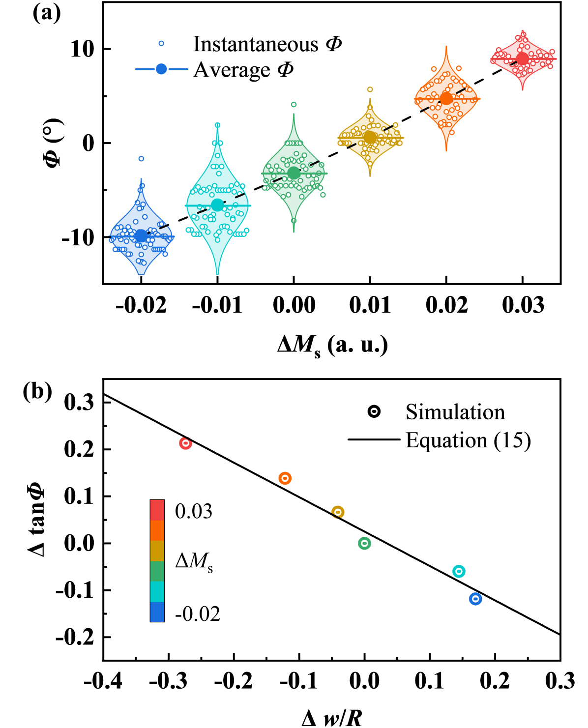
As the motion of skyrmion is a continuous process, we are more interested in its total displacement over a certain period of time. Therefore, we further calculate the average value of throughout the entire motion, presenting it alongside the instantaneous values in Fig. 5 (a). Figure 5 (a) is a violin plot with the instantaneous and average values of being represented by hollow and solid symbols, respectively. The curves on both sides of the violin shape display the probability density distribution, which clearly indicate a Gaussian distribution for all . When the variation in is within 5% (ranging from to ), the change in can reach up to °, and it exhibits an approximately linear correlation with . Specifically, when is , the average value of is only °, indicating an extremely small SkHE.
III.3 Analysis based on Thiele equation
In this section, we theoretically analyze of the simulation results. While the size of a Néel skyrmion may change, its central symmetry in shape remains unchanged, which allows us to model it as a rigid point-like particle. Therefore, its motion can be qualitatively elucidated by a modified Thiele equation [89]
| (10) |
The three terms arise from the precessional, damping, and SOT terms in the LLG equation, respectively. Here, is the gyromagnetic coupling vector, is the dissipative tensor, and the tensor quantifies the efficiency of the spin Hall torque over the two-dimensional configuration. The parameters and correspond respectively to the topological invariant as a sum of the solid angles of magnetizations, and the component of the disspation tensor as an indicator of the magnetization rotation length-scale, given by
| (11) | |||
| (12) |
For a FM skyrmion with a simple profile, is approximately given by [23], while for a FiM skyrmion with roughly as large as , it is given by [57]. This means that is expected to scale likewise with the normalized skyrmion radius presented in Fig. 2 (e). In our model, due to the presence of spatially dependent , the skyrmion internal configuration changes with , resulting in the variation of during the skyrmion motion, where is the proportionality coefficient.
The solutions of Eq. (10) are
| (13) | ||||
| (14) |
where is a constant derived from the tensor . Equations (13) and (14) can be used to explain the results of instantaneous velocity in Figs. 4 (c) and (d). When is small enough, the term can be neglected, so that becomes independent of , manifested in Fig. 4 (d) as almost unrelated to . As for , the term cannot be neglected, so that is related to , i.e., correlated with , as seen in Fig. 4 (c), where exhibits an approximate linear correlation with .
Regarding the variation of the skyrmion Hall angle , it follows the relation
| (15) |
The above Eq. (15) can be used to explain the simulation results shown in Fig. 5 (a). The original variable affects the internal skyrmion configuration , causing an incremental change during the motion process. This further leads to an increment of . When takes an appropriate value, around in this work, precisely compensates for the original , thus suppressing the skyrmion Hall effect. To visually demonstrate the relationship in Eq. (15), we plot the function of with respect to , as shown in Fig. 5 (b). This function reveals the correlation between the changes in and the normalized skyrmion radius. We find that the simulation results for different are uniformly distributed around the theoretical line, and the linear relationship conforms to the description provided by Eq. (15).
IV Conclusion
In conclusion, we have investigated the static properties and current-induced dynamics of the synthetic FiM skyrmions. Compared to the FM skyrmions, equilibrium FiM skyrmions exhibit a higher sensitivity of their static profiles to the variation in . Inspired by the graded- in the field of graded-index magnonics, we have explore the influence of a gradient on the skyrmion dynamics by particularly focus on the SOT-induced motion. It is shown that the presence of a gradient significantly affects the trajectory, velocity, and size of the driven skyrmion. Notedly, a 5% variation in gradient can control the skyrmion Hall angle within a range of °. Specifically, a 1% gradient completely suppresses the SkHE. We have analyzed the simulation results using Thiele theory, demonstrating that the gradient regulates the skyrmion Hall angle by influencing the normalized skyrmion radius. In this study, we have incorporated the gradient from the magnonics to the skyrmionics. Our findings are expected to provide a new perspective to overcome the SkHE, which has been an obstacle to the technical applications of skyrmions so far.
Acknowledgements.
X.F.Z. acknowledges support by the National Science Fund for Distinguished Young Scholars (Grant No. 52225312), the National Natural Science Foundation of China (Grant No. U1908220), and the Key Research and Development Program of Zhejiang Province (Grant No. 2021C01033). X.C.Z. and M.M. acknowledge support by the JST CREST (Grant No. JPMJCR20T1). M.M. also acknowledges support by the JSPS KAKENHI (Grants No. JP20H00337, No. JP23H04522 and No. JP24H02231), and the Waseda University Grant for Special Research Projects (Grant No. 2024C-153). L.B. acknowledges the financial support by China Scholarship Council (Grant No. 202206080023).References
- Roessler et al. [2006] U. K. Roessler, A. Bogdanov, and C. Pfleiderer, Spontaneous skyrmion ground states in magnetic metals, Nature 442, 797 (2006).
- Nagaosa and Tokura [2013] N. Nagaosa and Y. Tokura, Topological properties and dynamics of magnetic skyrmions, Nature Nanotechnology 8, 899 (2013).
- Mochizuki and Seki [2015] M. Mochizuki and S. Seki, Dynamical magnetoelectric phenomena of multiferroic skyrmions, Journal of Physics: Condensed Matter 27, 503001 (2015).
- Jiang et al. [2017a] W. Jiang, G. Chen, K. Liu, J. Zang, S. G. Te Velthuis, and A. Hoffmann, Skyrmions in magnetic multilayers, Physics Reports 704, 1 (2017a).
- Kanazawa et al. [2017] N. Kanazawa, S. Seki, and Y. Tokura, Noncentrosymmetric magnets hosting magnetic skyrmions, Advanced Materials 29, 1603227 (2017).
- Finocchio et al. [2016] G. Finocchio, F. Büttner, R. Tomasello, M. Carpentieri, and M. Kläui, Magnetic skyrmions: from fundamental to applications, Journal of Physics D: Applied Physics 49, 423001 (2016).
- Kang et al. [2016] W. Kang, Y. Huang, X. Zhang, Y. Zhou, and W. Zhao, Skyrmion-electronics: An overview and outlook, Proceedings of the IEEE 104, 2040 (2016).
- Fert et al. [2017] A. Fert, N. Reyren, and V. Cros, Magnetic skyrmions: advances in physics and potential applications, Nature Reviews Materials 2, 1 (2017).
- Everschor-Sitte et al. [2018] K. Everschor-Sitte, J. Masell, R. M. Reeve, and M. Kläui, Perspective: Magnetic skyrmions—overview of recent progress in an active research field, Journal of Applied Physics 124 (2018).
- Tokura and Kanazawa [2020] Y. Tokura and N. Kanazawa, Magnetic skyrmion materials, Chemical Reviews 121, 2857 (2020).
- Back et al. [2020] C. Back, V. Cros, H. Ebert, K. Everschor-Sitte, A. Fert, M. Garst, T. Ma, S. Mankovsky, T. Monchesky, M. Mostovoy, et al., The 2020 skyrmionics roadmap, Journal of Physics D: Applied Physics 53, 363001 (2020).
- Zhang et al. [2020] X. Zhang, Y. Zhou, K. M. Song, T.-E. Park, J. Xia, M. Ezawa, X. Liu, W. Zhao, G. Zhao, and S. Woo, Skyrmion-electronics: writing, deleting, reading and processing magnetic skyrmions toward spintronic applications, Journal of Physics: Condensed Matter 32, 143001 (2020).
- Bogdanov and Panagopoulos [2020] A. N. Bogdanov and C. Panagopoulos, Physical foundations and basic properties of magnetic skyrmions, Nature Reviews Physics 2, 492 (2020).
- Dieny et al. [2020] B. Dieny, I. L. Prejbeanu, K. Garello, P. Gambardella, P. Freitas, R. Lehndorff, W. Raberg, U. Ebels, S. O. Demokritov, J. Akerman, et al., Opportunities and challenges for spintronics in the microelectronics industry, Nature Electronics 3, 446 (2020).
- Bo et al. [2022] L. Bo, C. Hu, R. Zhao, and X. Zhang, Micromagnetic manipulation and spin excitation of skyrmionic structures, Journal of Physics D: Applied Physics (2022).
- Psaroudaki and Panagopoulos [2021] C. Psaroudaki and C. Panagopoulos, Skyrmion qubits: A new class of quantum logic elements based on nanoscale magnetization, Physical Review Letters 127, 067201 (2021).
- Psaroudaki et al. [2023] C. Psaroudaki, E. Peraticos, and C. Panagopoulos, Skyrmion qubits: Challenges for future quantum computing applications, Applied Physics Letters 123 (2023).
- Xia et al. [2023] J. Xia, X. Zhang, X. Liu, Y. Zhou, and M. Ezawa, Universal quantum computation based on nanoscale skyrmion helicity qubits in frustrated magnets, Physical Review Letters 130, 106701 (2023).
- Yu et al. [2010] X. Yu, Y. Onose, N. Kanazawa, J. H. Park, J. Han, Y. Matsui, N. Nagaosa, and Y. Tokura, Real-space observation of a two-dimensional skyrmion crystal, Nature 465, 901 (2010).
- Zang et al. [2011] J. Zang, M. Mostovoy, J. H. Han, and N. Nagaosa, Dynamics of skyrmion crystals in metallic thin films, Physical Review Letters 107, 136804 (2011).
- Iwasaki et al. [2013a] J. Iwasaki, M. Mochizuki, and N. Nagaosa, Current-induced skyrmion dynamics in constricted geometries, Nature Nanotechnology 8, 742 (2013a).
- Iwasaki et al. [2013b] J. Iwasaki, M. Mochizuki, and N. Nagaosa, Universal current-velocity relation of skyrmion motion in chiral magnets, Nature Communications 4, 1463 (2013b).
- Jiang et al. [2017b] W. Jiang, X. Zhang, G. Yu, W. Zhang, X. Wang, M. Benjamin Jungfleisch, J. E. Pearson, X. Cheng, O. Heinonen, K. L. Wang, et al., Direct observation of the skyrmion hall effect, Nature Physics 13, 162 (2017b).
- Litzius et al. [2017] K. Litzius, I. Lemesh, B. Krüger, P. Bassirian, L. Caretta, K. Richter, F. Büttner, K. Sato, O. A. Tretiakov, J. Förster, et al., Skyrmion hall effect revealed by direct time-resolved x-ray microscopy, Nature Physics 13, 170 (2017).
- Chen [2017] G. Chen, Skyrmion hall effect, Nature Physics 13, 112 (2017).
- Tomasello et al. [2018a] R. Tomasello, A. Giordano, S. Chiappini, R. Zivieri, G. Siracusano, V. Puliafito, I. Medlej, A. La Corte, B. Azzerboni, M. Carpentieri, et al., Micromagnetic understanding of the skyrmion hall angle current dependence in perpendicularly magnetized ferromagnets, Physical Review B 98, 224418 (2018a).
- Purnama et al. [2015] I. Purnama, W. L. Gan, D. W. Wong, and W. S. Lew, Guided current-induced skyrmion motion in 1d potential well, Scientific reports 5, 10620 (2015).
- Zhang et al. [2015] X. Zhang, G. Zhao, H. Fangohr, J. P. Liu, W. Xia, J. Xia, and F. Morvan, Skyrmion-skyrmion and skyrmion-edge repulsions in skyrmion-based racetrack memory, Scientific reports 5, 7643 (2015).
- Rosales et al. [2015] H. D. Rosales, D. C. Cabra, and P. Pujol, Three-sublattice skyrmion crystal in the antiferromagnetic triangular lattice, Physical Review B 92, 214439 (2015).
- Barker and Tretiakov [2016] J. Barker and O. A. Tretiakov, Static and dynamical properties of antiferromagnetic skyrmions in the presence of applied current and temperature, Physical Review Letters 116, 147203 (2016).
- Zhang et al. [2016a] X. Zhang, M. Ezawa, and Y. Zhou, Thermally stable magnetic skyrmions in multilayer synthetic antiferromagnetic racetracks, Physical Review B 94, 064406 (2016a).
- Zhang et al. [2016b] X. Zhang, Y. Zhou, and M. Ezawa, Magnetic bilayer-skyrmions without skyrmion hall effect, Nature Communications 7, 10293 (2016b).
- Tomasello et al. [2017] R. Tomasello, V. Puliafito, E. Martinez, A. Manchon, M. Ricci, M. Carpentieri, and G. Finocchio, Performance of synthetic antiferromagnetic racetrack memory: domain wall versus skyrmion, Journal of Physics D: Applied Physics 50, 325302 (2017).
- Duine et al. [2018] R. Duine, K.-J. Lee, S. S. Parkin, and M. D. Stiles, Synthetic antiferromagnetic spintronics, Nature Physics 14, 217 (2018).
- Moriyama et al. [2018] T. Moriyama, W. Zhou, T. Seki, K. Takanashi, and T. Ono, Spin-orbit-torque memory operation of synthetic antiferromagnets, Physical Review Letters 121, 167202 (2018).
- Dohi et al. [2019] T. Dohi, S. DuttaGupta, S. Fukami, and H. Ohno, Formation and current-induced motion of synthetic antiferromagnetic skyrmion bubbles, Nature Communications 10, 5153 (2019).
- Xia et al. [2019] J. Xia, X. Zhang, M. Ezawa, Z. Hou, W. Wang, X. Liu, and Y. Zhou, Current-driven dynamics of frustrated skyrmions in a synthetic antiferromagnetic bilayer, Physical Review Applied 11, 044046 (2019).
- Legrand et al. [2020] W. Legrand, D. Maccariello, F. Ajejas, S. Collin, A. Vecchiola, K. Bouzehouane, N. Reyren, V. Cros, and A. Fert, Room-temperature stabilization of antiferromagnetic skyrmions in synthetic antiferromagnets, Nature Materials 19, 34 (2020).
- Salimath et al. [2020] A. Salimath, F. Zhuo, R. Tomasello, G. Finocchio, and A. Manchon, Controlling the deformation of antiferromagnetic skyrmions in the high-velocity regime, Physical Review B 101, 024429 (2020).
- Gao et al. [2020] S. Gao, H. D. Rosales, F. A. Gomez Albarracin, V. Tsurkan, G. Kaur, T. Fennell, P. Steffens, M. Boehm, P. Čermák, A. Schneidewind, et al., Fractional antiferromagnetic skyrmion lattice induced by anisotropic couplings, Nature 586, 37 (2020).
- Xia et al. [2021] J. Xia, X. Zhang, K.-Y. Mak, M. Ezawa, O. A. Tretiakov, Y. Zhou, G. Zhao, and X. Liu, Current-induced dynamics of skyrmion tubes in synthetic antiferromagnetic multilayers, Physical Review B 103, 174408 (2021).
- Mohylna et al. [2022] M. Mohylna, F. G. Albarracín, M. Žukovič, and H. D. Rosales, Spontaneous antiferromagnetic skyrmion/antiskyrmion lattice and spiral spin-liquid states in the frustrated triangular lattice, Physical Review B 106, 224406 (2022).
- Aldarawsheh et al. [2022] A. Aldarawsheh, I. L. Fernandes, S. Brinker, M. Sallermann, M. Abusaa, S. Blügel, and S. Lounis, Emergence of zero-field non-synthetic single and interchained antiferromagnetic skyrmions in thin films, Nature Communications 13, 7369 (2022).
- Aldarawsheh et al. [2023] A. Aldarawsheh, M. Sallermann, M. Abusaa, and S. Lounis, A spin model for intrinsic antiferromagnetic skyrmions on a triangular lattice, Frontiers in Physics 11, 1175317 (2023).
- Barker et al. [2023] C. E. Barker, E. Haltz, T. Moore, C. H. Marrows, et al., Breathing modes of skyrmion strings in a synthetic antiferromagnet multilayer, Journal of Applied Physics 133 (2023).
- Barker et al. [2024] C. E. Barker, K. Fallon, C. Barton, E. Haltz, T. P. Almeida, S. Villa, C. Kirkbride, F. Maccherozzi, B. Sarpi, S. S. Dhesi, et al., Phase coexistence and transitions between antiferromagnetic and ferromagnetic states in a synthetic antiferromagnet, arXiv preprint arXiv:2401.16273 (2024).
- Aldarawsheh et al. [2024] A. Aldarawsheh, M. Sallermann, M. Abusaa, and S. Lounis, Current-driven dynamics of antiferromagnetic skyrmions: from skyrmion hall effects to hybrid inter-skyrmion scattering, arXiv preprint arXiv:2403.01987 (2024).
- Jungwirth et al. [2016] T. Jungwirth, X. Marti, P. Wadley, and J. Wunderlich, Antiferromagnetic spintronics, Nature Nanotechnology 11, 231 (2016).
- Weißenhofer and Nowak [2023] M. Weißenhofer and U. Nowak, Temperature dependence of current-driven and brownian skyrmion dynamics in ferrimagnets with compensation point, Physical Review B 107, 064423 (2023).
- Kim et al. [2017] S. K. Kim, K.-J. Lee, and Y. Tserkovnyak, Self-focusing skyrmion racetracks in ferrimagnets, Physical Review B 95, 140404 (2017).
- Kim et al. [2019] S. K. Kim, K. Nakata, D. Loss, and Y. Tserkovnyak, Tunable magnonic thermal hall effect in skyrmion crystal phases of ferrimagnets, Physical Review Letters 122, 057204 (2019).
- Woo et al. [2018] S. Woo, K. M. Song, X. Zhang, Y. Zhou, M. Ezawa, X. Liu, S. Finizio, J. Raabe, N. J. Lee, S.-I. Kim, et al., Current-driven dynamics and inhibition of the skyrmion hall effect of ferrimagnetic skyrmions in gdfeco films, Nature Communications 9, 959 (2018).
- Hirata et al. [2019] Y. Hirata, D.-H. Kim, S. K. Kim, D.-K. Lee, S.-H. Oh, D.-Y. Kim, T. Nishimura, T. Okuno, Y. Futakawa, H. Yoshikawa, et al., Vanishing skyrmion hall effect at the angular momentum compensation temperature of a ferrimagnet, Nature Nanotechnology 14, 232 (2019).
- Brandão et al. [2019] J. Brandão, D. Dugato, M. Puydinger dos Santos, and J. Cezar, Evolution of zero-field ferrimagnetic domains and skyrmions in exchange-coupled pt/cogd/pt confined nanostructures: implications for antiferromagnetic devices, ACS Applied Nano Materials 2, 7532 (2019).
- Mandru et al. [2020] A.-O. Mandru, O. Yıldırım, R. Tomasello, P. Heistracher, M. Penedo, A. Giordano, D. Suess, G. Finocchio, and H. J. Hug, Coexistence of distinct skyrmion phases observed in hybrid ferromagnetic/ferrimagnetic multilayers, Nature Communications 11, 6365 (2020).
- Yıldırım et al. [2022] O. Yıldırım, R. Tomasello, Y. Feng, G. Carlotti, S. Tacchi, P. M. Vaghefi, A. Giordano, T. Dutta, G. Finocchio, H. J. Hug, et al., Tuning the coexistence regime of incomplete and tubular skyrmions in ferromagnetic/ferrimagnetic/ferromagnetic trilayers, ACS Applied Materials & Interfaces 14, 34002 (2022).
- Berges et al. [2022] L. Berges, E. Haltz, S. Panigrahy, S. Mallick, R. Weil, S. Rohart, A. Mougin, and J. Sampaio, Size-dependent mobility of skyrmions beyond pinning in ferrimagnetic gdco thin films, Physical Review B 106, 144408 (2022).
- Wang et al. [2022] X. Wang, A. R. Stuart, M. S. Swyt, C. M. Q. Flores, A. T. Clark, A. Fiagbenu, R. V. Chopdekar, P. N. Lapa, Z. Xiao, D. Keavney, et al., Topological spin memory of antiferromagnetically coupled skyrmion pairs in co/gd/pt multilayers, Physical Review Materials 6, 084412 (2022).
- Bläsing et al. [2018] R. Bläsing, T. Ma, S.-H. Yang, C. Garg, F. K. Dejene, A. T. N’Diaye, G. Chen, K. Liu, and S. S. Parkin, Exchange coupling torque in ferrimagnetic co/gd bilayer maximized near angular momentum compensation temperature, Nature Communications 9, 4984 (2018).
- [60] M. A. Müller, R. Lavrijsen, and T. Kools, Modelling SOT-Driven Domain Wall Motion in Pt/Co/Gd Multilayers with Mumax 3, Ph.D. thesis, Master Thesis TU/e, 2021.
- Li et al. [2023] P. Li, T. J. Kools, B. Koopmans, and R. Lavrijsen, Ultrafast racetrack based on compensated co/gd-based synthetic ferrimagnet with all-optical switching, Advanced Electronic Materials 9, 2200613 (2023).
- Das et al. [2023] D. Das, Y. Cen, J. Wang, and X. Fong, Bilayer-skyrmion-based design of neuron and synapse for spiking neural network, Physical Review Applied 19, 024063 (2023).
- Shen et al. [2024] Y. Shen, C. He, Z. Song, B. Chen, H. He, Y. Ma, J. A. Fells, S. J. Elston, S. M. Morris, M. J. Booth, et al., Topologically controlled multiskyrmions in photonic gradient-index lenses, Physical Review Applied 21, 024025 (2024).
- Davies and Kruglyak [2015] C. S. Davies and V. Kruglyak, Graded-index magnonics, Low Temperature Physics 41, 760 (2015).
- Davies et al. [2015] C. Davies, A. Francis, A. Sadovnikov, S. Chertopalov, M. Bryan, S. Grishin, D. Allwood, Y. P. Sharaevskii, S. Nikitov, and V. Kruglyak, Towards graded-index magnonics: Steering spin waves in magnonic networks, Physical Review B 92, 020408 (2015).
- Davies et al. [2017] C. Davies, V. Poimanov, and V. Kruglyak, Mapping the magnonic landscape in patterned magnetic structures, Physical Review B 96, 094430 (2017).
- Tomasello et al. [2018b] R. Tomasello, S. Komineas, G. Siracusano, M. Carpentieri, and G. Finocchio, Chiral skyrmions in an anisotropy gradient, Physical Review B 98, 024421 (2018b).
- Shen et al. [2018] L. Shen, J. Xia, G. Zhao, X. Zhang, M. Ezawa, O. A. Tretiakov, X. Liu, and Y. Zhou, Dynamics of the antiferromagnetic skyrmion induced by a magnetic anisotropy gradient, Physical Review B 98, 134448 (2018).
- de Assis et al. [2023] I. R. de Assis, I. Mertig, and B. Göbel, Skyrmion motion in magnetic anisotropy gradients: Acceleration caused by deformation, Physical Review B 108, 144438 (2023).
- Udalov et al. [2021] O. Udalov, I. Beloborodov, and M. Sapozhnikov, Magnetic skyrmions and bimerons in films with anisotropic interfacial dzyaloshinskii-moriya interaction, Physical Review B 103, 174416 (2021).
- Sapozhnikov et al. [2022] M. Sapozhnikov, R. Gorev, E. Skorokhodov, N. Gusev, A. Sadovnikov, and O. Udalov, Zigzag domains caused by strain-induced anisotropy of the dzyaloshinskii-moriya interaction, Physical Review B 105, 024405 (2022).
- Gorshkov et al. [2022] I. O. Gorshkov, R. V. Gorev, M. V. Sapozhnikov, and O. G. Udalov, Dmi-gradient-driven skyrmion motion, ACS Applied Electronic Materials 4, 3205 (2022).
- Vogel et al. [2018] M. Vogel, R. Aßmann, P. Pirro, A. V. Chumak, B. Hillebrands, and G. von Freymann, Control of spin-wave propagation using magnetisation gradients, Scientific Reports 8, 11099 (2018).
- Borys et al. [2019] P. Borys, N. Qureshi, C. Ordonez-Romero, and O. Kolokoltsev, Scattering of exchange spin waves from regions of modulated magnetization, Europhysics Letters 128, 17003 (2019).
- Gallardo et al. [2019] R. Gallardo, P. Alvarado-Seguel, T. Schneider, C. Gonzalez-Fuentes, A. Roldán-Molina, K. Lenz, J. Lindner, and P. Landeros, Spin-wave non-reciprocity in magnetization-graded ferromagnetic films, New Journal of Physics 21, 033026 (2019).
- Mieszczak et al. [2020] S. Mieszczak, O. Busel, P. Gruszecki, A. N. Kuchko, J. W. Kłos, and M. Krawczyk, Anomalous refraction of spin waves as a way to guide signals in curved magnonic multimode waveguides, Physical Review Applied 13, 054038 (2020).
- Borys et al. [2021] P. Borys, O. Kolokoltsev, N. Qureshi, M. Plumer, and T. Monchesky, Unidirectional spin wave propagation due to a saturation magnetization gradient, Physical Review B 103, 144411 (2021).
- Kolokoltsev et al. [2012] O. Kolokoltsev, N. Qureshi, E. Mejía-Uriarte, and C. L. Ordóñez-Romero, Hot spin-wave resonators and scatterers, Journal of Applied Physics 112 (2012).
- Vogel et al. [2015] M. Vogel, A. V. Chumak, E. H. Waller, T. Langner, V. I. Vasyuchka, B. Hillebrands, and G. Von Freymann, Optically reconfigurable magnetic materials, Nature Physics 11, 487 (2015).
- Tomasello et al. [2014] R. Tomasello, E. Martinez, R. Zivieri, L. Torres, M. Carpentieri, and G. Finocchio, A strategy for the design of skyrmion racetrack memories, Scientific Reports 4, 1 (2014).
- Zhang and Li [2004] S. Zhang and Z. Li, Roles of nonequilibrium conduction electrons on the magnetization dynamics of ferromagnets, Physical Review Letters 93, 127204 (2004).
- Yamane et al. [2016] Y. Yamane, J. Ieda, and J. Sinova, Spin-transfer torques in antiferromagnetic textures: Efficiency and quantification method, Physical Review B 94, 054409 (2016).
- Slonczewski [1996] J. C. Slonczewski, Current-driven excitation of magnetic multilayers, Journal of Magnetism and Magnetic Materials 159, L1 (1996).
- Vansteenkiste et al. [2014] A. Vansteenkiste, J. Leliaert, M. Dvornik, M. Helsen, F. Garcia-Sanchez, and B. Van Waeyenberge, The design and verification of mumax3, AIP Advances 4 (2014).
- Lalieu et al. [2017] M. Lalieu, M. Peeters, S. Haenen, R. Lavrijsen, and B. Koopmans, Deterministic all-optical switching of synthetic ferrimagnets using single femtosecond laser pulses, Physical Review B 96, 220411 (2017).
- Wang et al. [2018] X. Wang, H. Yuan, and X. Wang, A theory on skyrmion size, Communications Physics 1, 31 (2018).
- Morota et al. [2011] M. Morota, Y. Niimi, K. Ohnishi, D. Wei, T. Tanaka, H. Kontani, T. Kimura, and Y. Otani, Indication of intrinsic spin hall effect in 4 d and 5 d transition metals, Physical Review B 83, 174405 (2011).
- Beg et al. [2015] M. Beg, R. Carey, W. Wang, D. Cortés-Ortuño, M. Vousden, M.-A. Bisotti, M. Albert, D. Chernyshenko, O. Hovorka, R. L. Stamps, et al., Ground state search, hysteretic behaviour and reversal mechanism of skyrmionic textures in confined helimagnetic nanostructures, Scientific Reports 5, 17137 (2015).
- Thiele [1973] A. Thiele, Steady-state motion of magnetic domains, Physical Review Letters 30, 230 (1973).