A digger for 2D densely-packed coarse granular media using vibrations
Abstract
We create a manually-operated mechanical digger able to move within 2D densely packed granular media, in a manner intrinsically different from the existing biomimic diggers. The characteristics of our design include that the average grain size is about one tenth as large as the digger, the area packing density is about of the jamming density , and the value of the dimensionless inertial number is in the quasi-static regime. Unlike conventional autonomous diggers that move by fluidizing the surrounding granular media with a much finer grain size, our digger swiftly bypasses this mobility mechanism as coarse grains with interparticle friction are hard to be fluidized. To achieve this, the digger has a circular shape and singly captures granular particles near the front entrance of the recess formed by the center unit running across its body using the equipped vibrating claw and then ejects the captured particles backwards. We validate this moving strategy in both experiments and numerical simulations, and demonstrate that the moving efficiency can be enhanced by the judgement of the human operator but the effectiveness is not significantly influenced by the shape of granular particles. In addition, localized vibration from the claw is needed to degrade friction between interlocked irregular-shaped particles.
I Introduction
Digging and moving granular materials are common engineering processes and have important industrial applications, but the facility design is far from well-established due to the unique nature of the materials. Systems composed of granular materials such as sand, gravel, and drift ice are athermal and non-equilibrium because the energy required to lift a single granular particle to a height comparable to its size under gravity is usually much larger than the equilibrium thermal fluctuation energy. For thermal materials, such as air and water, their equilibrium characteristics allow a universal governing equation (e.g. the well-known Navier-Stokes equation) for predicting the behavior of manmade objects moving within them. Granular systems, on the other hand, lack this kind of fundamental governing equation of motion and usually stay still without a continuous injection of external energy. Granular materials can also transit from being fluid-like to a disordered solid-like state if the packing density becomes higher than the jamming density Behringer and Chakraborty (2019) ( in 2D). These bi-phasic complex features make designing a digging machine (digger) mobile in dense athermal materials both challenging and less explored.
If we treat the packed granular particles as a viscoplastic material, its flowing state may be characterized by the dimensionless inertial number , defined as
| (1) |
where is a characteristic grain size, is characteristic pressure, is the granular particle density, and is a characteristic shear rate. Both and are intrinsic properties of the granular material, whereas and are determined by the extrinsic environment, such as a manmade digger, interacting with the material. The numerator in Eqn. 1 can be viewed as a microscopic time scale related to local particle rearrangements caused by exerted by the environment. The denominator in Eqn. 1, on the other hand, can be viewed as a macroscopic time scale related to global particle rearrangements due to .
The typical stress generated by an animal digger or its bio-inspired counterpart, which sets a scale for , is about kPa. The typical frequency at which a digger changes its body shape to relocate granular particles is about Hz or lower, which sets a scale for .
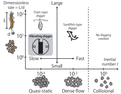
Hence, the inertial number can measure how easily a digger can move within a granular medium, from the digger’s point of view. In addition, the digger size relative to the characteristic grain size is also an important parameter affecting the mobility of the digger. Generally, diggers in granular media can be classified based on their working environment (using the inertial number ) and their size relative to granular particle size (using dimensionless size ) Hosoi and Goldman (2015); Kamrin et al. (2024), as shown in Fig. 1. All known man-made autonomous diggers exist in the regime of ; however, can either be in the quasi-static regime or the dense-flow regime. In the quasi-static regime with , we find clam-type diggers around which the macroscopic deformation of the granular medium is much slower than the microscopic rearrangements. In contrast, in the dense flow regime with , we find sandfish-type and snake-type diggers around which the macroscopic and the microscopic rearrangements take comparable durations. This opposite behavior is triggered by a digger when it moves.
Specifically, there are a finite number of attempts that challenge the design of a mobile digger for densely-packed granular media. Except for a few artificial designs Gao (2019), the majority are bio-inspired and mimic the movements of organisms Goldman (2014); Hosoi and Goldman (2015); Aguilar et al. (2016); Astley et al. (2020); Rühs et al. (2021); Dorgan and Daltorio (2023) such as bacteria B.Rodenborna et al. (2012); Valdés et al. (2019), snakes Astley et al. (2015); Rieser et al. (2019), sandfish lizards Shimada et al. (2009); Maladen et al. (2009); Li et al. (2013); Sharpe et al. (2014); Peng et al. (2016), bristled worms Ortiz et al. (2019), earthworms Borela et al. (2021); Ozkan-Aydin et al. (2022), plant roots Naclerio et al. (2018, 2021), self-burying seeds Tang et al. (2024), razor clams Winter and Hosoi (2011); Winter et al. (2012, 2014); Tao et al. (2020); Huang and Tao (2020), or mole crabs Treers et al. (2022). The intricate movements of these bio-inspired diggers necessitate disturbing the surrounding granular media of to sufficient extent to move forward. In other words, these man-made autonomous diggers move by following a prescribed procedure of altering their shapes, and the effectiveness of the procedure is guaranteed by the yielding characteristics of the surrounding granular media to a state away from jamming. This kind of strategy does not work in the regime of . When the size of a single grain is comparable to that of the space created by the digger using its moving parts, or even a portion of it, the interparticle friction becomes difficult to overcome. As a result, the digger can no longer fluidize the surrounding granular particles easily and they become a major obstacle that stops the digger from moving.
To address this problem, we propose a human-operated digger that locally reduces interparticle friction by small yet focused vibrations and relocates granular particles one at a time using a repetitive procedure. Our design minimizes the necessity of the yield and fluidization of the surrounding grains. For the sake of simplicity, we test the idea by designing a flat digger that moves on a surface and is not allowed to climb over obstacles around it. The idea, however, in principle can be extended to a 3D environment. Our digger has a circular shape and is equipped with an internal recess and a vibrating claw. The circular shape allows the digger to rotate and change its moving direction easily with minimal disturbance to the adjacent granular particles. The digger also does not need to excavate a tunnel to proceed, meaning that the crushing of surrounding granular particles is not a concern. Instead, we create an internal recess within the digger. The internal recess starts with an opening on the front edge of the digger. With the help of the vibrating claw, the interparticle friction is significantly reduced around the recess. This allows the digger to individually loosen, capture, and relocate interlocked gravel grains blocking its way. So far, there is no bio-inspired digger equipped with a vibrating function since animals do not vibrate to move forward in a packed granular medium. The vibrating claw serves as a key component in the mobility of our digger. Experimentally, using mechanical vibrations of low frequency ( Hz) Texier et al. (2017) or ultrasonic vibrations ( kHz) Firstbrook et al. (2017) with small amplitude ( m) has been reported to effectively reduce the force resisting the penetration of an intruder into a dry granular medium composed of grains much smaller than the intruder, an effect known as acoustic fluidization Melosh (1996); Espíndola et al. (2012). Our prototype digger would be the first to utilize localized vibrations in digging forward and its success is tied with the disturbed granular flow state as characterized below.
Our digger can move interlocked irregular-shaped gravel grains at an average time interval of seconds, which converts to a rate of Hz and sets the scale for . The claw vibrates at a frequency Hz and a small amplitude of a few millimeters, meaning that . The tip of the vibrating claw can exert a typical pressure of about kPa. We operate our digger within a layer of densely packed granular particles of area packing density close to and , where m, m, and . Therefore, we estimate the value of for the vibrating digger is approximately . This places our digger in the quasi-static regime with no large plastic motion of the granular medium. In summary, we estimate that our manual vibrating digger sits close to the bottom of the large-and-slow regime in Fig. 1.
II The Experimental Setup and Vibrating Digger
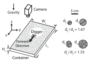
To validate the design of our digger, we prepared a simple two-dimensional test bed, a container that measures () in width, () in length, and () in height and accommodates a layer of densely packed granular particles. The time-lapse positions of the digger are captured by a digital camera with a top-down view of the container to evaluate its mobility. The schematic diagram of the experimental setup is shown in Fig. 2 which includes a layer of granular particles and our digger.
The circular digger measures () in diameter, is driven by two independent wheels, and has a center unit that sits along one diameter of the digger and hosts a vibrating claw. The center unit is driven by its own gearbox and can shift linearly back and forth along a track. A vibrating claw is attached to the center unit and is vibrated at a frequency Hz by an FA-130 motor placed close to the claw and near the front of the digger. The two driving wheels allow the digger to move forward, move backward, or pivot on a surface. Each wheel is driven by a separate gearbox. All of the gearboxes are identical, equipped with an FA-130 motor powered by two 1.2 V, 2,450 mAh Ni-MH batteries, and set at a low-speed gear ratio of 719:1 to output a high torque. To minimize any possible performance issues associated with low batteries, we ensure that all batteries are drained by no more than of the fully charged voltage of V for each experiment. It is noted that the digger is constructed of commercially available parts produced by Tamiya. A schematic of our vibrating digger is shown in Fig. 3(a).
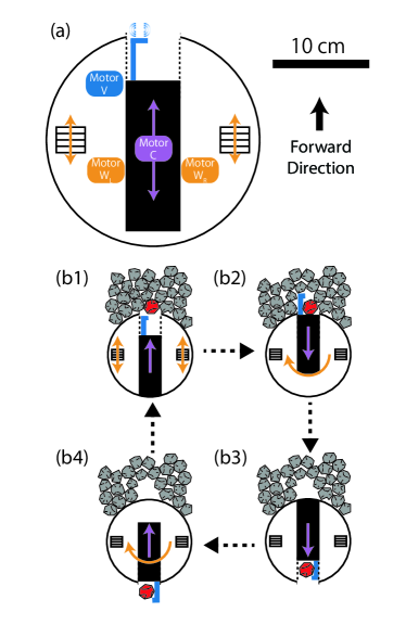
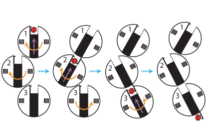
The digger moves through granular particles by following a repetitive moving procedure, which can be decomposed into four steps, as shown in Fig. 3(b). First, the digger wiggles to capture into its front recess, formed by the center unit, the simple-shaped granular particles blocking its movement. For irregular-shaped granular particles that interlock easily, capturing them solely by wiggling is almost unfeasible. To overcome this, the digger can position its vibrating claw to loosen the interlocked granular particles and then capture one or a few. Second, the digger wiggles and retrieves the claw (if used) to secure the captured particles within its recess while rotating degrees by the wheels. After that, the digger uses its center unit to eject the captured particles backwards. Last, the center unit retreats to the original configuration, and the digger rotates by degrees again to get ready to repeat the procedure. After one moving procedure, the digger proceeds by a distance much shorter than its size, but repetitions of the procedure can lead the digger to move a long distance.
To test the effect of particle shape on the performance of the digger, we use two kinds of granular particles: simple-shaped wood cylinders and irregular-shaped granite gravels. Since the digger exhibits only the planar movement, we use the 2D area packing density to quantify the compactness of granular particles. For a system containing cylinders of diameter and base area , is defined as
| (2) |
where is the base area of the circular digger. The cylinders are 50-50 bidisperse with a diameter of or and a diameter ratio of to avoid artificial crystallization. When using cylindrical particles, we choose to make sure that the system is close to () the jamming regime of , and is dominated by the interparticle friction and difficult to fluidize.
For a system containing irregular-shaped granite gravels where is not well defined, we treat the system as a quasi-2D porous medium to estimate a characteristic area for each gravel by Jung (2010). Here, is the weight of a single granite gravel; is the density of granite; and is the average height of the quasi-2D gravel layer. To measure , we divided the container into an equally-spaced -by- matrix of segments with , measured the height of each segment, and took the average of to obtain . Once the ’s are evaluated, the estimated packing density of the porous granular medium is given by
| (3) |
Similar to the wood cylinders, the gravel is roughly 50-50 bidisperse with an estimated diameter of or and a diameter ratio of to avoid potential ordered structure or excessive local void. We choose when testing with the irregular-shaped particles. This value was chosen to be close to that tested with the regular-shaped cylinders as for the irregular-shaped particles is unknown.
III Results and Discussion
We first test the digger within a layer of wood cylinders whose simple geometry allows the digger to move forward by relocating the cylinders without using vibrations. As it is the operator who decides which cylinder to be relocated, there may be subjective discretion affecting the digger’s performance. To validate the proposed moving procedure, we conduct corresponding numerical discrete element simulations that give no preference to particles. Comparing the experimental and numerical results, we find that the spatial distributions of relocated particles are similar in both cases. Interestingly, human control demonstrates more flexibility because the operator can control things like where to eject the captured cylinders to help the digger adapt to the in-situ situation and move more efficiently. This kind of intentional adaptability cannot be easily achieved with a routine numerical algorithm. Nonetheless, the repetitive moving procedure can still be confirmed effective for digger’s mobility.
Next, we investigate the influence of particle shape on the performance of the digger by replacing the simple-shaped wood cylinders with irregular-shaped granite gravels. We do find that vibrations are necessary for the digger to proceed within irregular-shaped granular particles, but otherwise the spatial distributions of relocated particles are again not significantly influenced by the particle shape and associated with the moving procedure of the digger.
It is noted that for each case, we found dynamically similar results using at least three trials and only report a representative one.
III.1 The digger in a layer of simple-shaped cylindrical particles
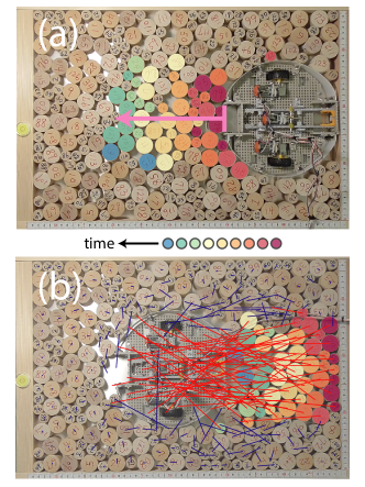
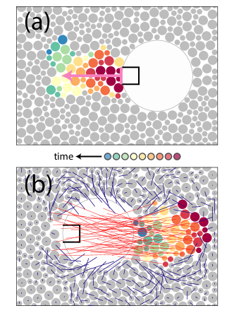
The simplest experimental setup to validate the repetitive moving procedure is to use granular particles with a simple geometry. With no chance of interlocking between particles, the digger can proceed without using vibrations. We test this using cylindrical granular particles with a . The initial configuration of the system (i.e. before the digger moved by a distance comparable to its size) is shown in Fig. 4(a), where particles are colored from red to blue according to the chronological order in which they were relocated during the operation. Fig. 4(b) shows the final configuration of the system after the movement of the digger.
Particles close to the digger must be moved earlier than particles farther away from the digger. Additionally, only particles relocated by the digger have long displacements comparable to, or slightly longer than, the diameter of the digger. Particles disturbed by the digger during its motion mostly have very short displacements and stay around their initial positions. The few exceptions are the results of the human operator judging that disturbing them would enhance mobility but are not the crucial bottlenecks. In other words, global collective particle rearrangements rarely happen in this localized rearrangement around in the quasi-static regime. We also notice that the transverse width of the spatial distribution of relocated particles, perpendicular to the forward direction of the digger, is similar to the diameter of the digger, which is inherent in the digger’s 180-degree rotation in the moving procedure.
To test whether the judgement of the human operator of the digger affects the spatial distribution of the relocated particles, that in turn may affect the digger’s performance, we developed a qualitative digger model using the discrete element method (DEM). The simulated digger pushes forward, and the particles entering its front recess and ejected to its rear are selected without giving a subjective preference. In the numerical simulations we use the same area packing density as the one in our experiments. The digger is driven quasi-statically, which approximates the small inertial number experimental environment. The DEM simulation is a simplified version of how a particle is ejected in the experiment without the rotations of the digger in the two steps of (b2) and (b4) in Fig. 3 and shall provide only qualitative responses to the experimental system (i.e., the captured particles are placed to the rear of the digger and ejected by the modeled elastic normal force, defined in Eqn. 7, which functions like the center unit). The details of the DEM algorithm can be found in the Appendix and reference Gao (2019).
The system configurations before and after the digger moved by a distance similar to its size are shown in Fig. 5(a) and Fig. 5(b), respectively. The spatial distributions of relocated particles are strikingly similar in both the experiment and the simulation. In simulation, however, the relocated particles are somewhat more concentrated in width and the particle displacement lines are distributed more symmetrically on the two lateral sides of the digger. This occurs because the simulated digger moves by the simple numerical procedure which always ejects particles to the rear of itself. In the experiment, the human operator can selectively eject the captured granular particles in any direction or merely choose to locally shift them, as demonstrated by the particle displacement lines across the digger in Fig. 4(b).
The simulation result further allows us to evaluate the digger’s mobility in view of how many cylinders have been relocated (via ejections) after the digger pushes forward quasi-statically to attempt advancement. The accumulated number of ejected particles, , are plotted against the total number of pushes by the digger, , in Fig. 6. The simulation result shows that after ejecting several granular particles, the digger gets stuck temporarily – that is, the digger ejects no particles even though it makes many advancement attempts by exerting quasi-static pushes against neighboring particles. After that, the digger becomes efficient again, presumably due to global rearrangements of particles affected by the digger, and can eject several more particles before getting stuck once more. This scenario recurs from time to time and is reflected in the stepwise shape of the and curve.

III.2 The digger in a layer of irregular-shaped particles
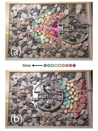
Having verified that the moving procedure does work for a layer of bidisperse simple-shaped cylinders, we further tested the influence of particle geometry using irregular-shaped gravels of packing density (similar to that of the wood cylinders with ). The configurations of the system before and after the digger has moved by a distance comparable to its size are shown in Fig. 7(a) and Fig. 7(b), respectively. Particles are colored chronologically in the same fashion as in Fig. 4. The motion of the digger within irregular-shaped gravels is much slower than within simple-shaped cylinders as there are interlockings between gravels to be overcome. However, the spatial distributions of relocated particles in both Fig. 4 and Fig. 7 are comparable. The results show that increasing the complexity of particle shape notably hinders the quantitative mobility of the digger and therefore , but the particles that must be relocated for the digger to move forward are qualitatively similar and the proposed moving procedure is indeed the key mechanism that permits the mobility of our digger in the low -low regime on the classification map in Fig. 1.
IV Conclusions
In this study, we propose a manually-operated vibrating digger capable of moving within a layer of densely packed granular particles with an average grain size about one tenth as large as the digger. This is intrinsically different from previous bio-inspired autonomous diggers mimicking the intricate movements of organisms living in sand, and to move forward, they rely on the yield and the fluidization of surrounding grains that are much smaller than the digger. Our manual digger has a circular shape with a recess in the front and a vibrating claw that allows it to capture and then eject sizable granular particles. This design empowers our digger to navigate working environments that are hard to fluidize globally due to comparably strong interparticle friction and hence difficult for bio-inspired diggers to negotiate.
We first tested our manual digger within simple-shaped wood cylinders and compared our experimental results with the simulation that is independent of the human judgement on the operation of the digger. The strong similarity between the experimental and numerical results indicates that the digger with its mobility mechanism can potentially become fully autonomous. However, we have also found that an operator’s dexterity and flexibility can help the digger move more efficiently by adapting to the ever-changing on-site situation. We then changed the granular medium to irregular-shaped gravels to test the influence of particle shape on the mobility performance of the digger. The complicated shape of gravel requires the digger to activate its vibrating claw to loosen interlocked granular particles. While the digger moves much slower in irregular-shaped gravels than in regular-shaped cylinders, the distribution of the relocated particles before and after the digger’s advancement stays almost the same. This similarity proves the feasibility of the relocation-for-advancement mechanism uniquely achieved by the current design.
In this study, the claw vibrates at a fixed frequency about Hz. However, in general, the vibrating frequency of the claw could be optimized, as indicated by studies of vibrating machines such as ballast tampers which use claw-like tines vibrating at an optimal frequency of Hz to fluidize the ballast for railroad track maintenance. Too low a frequency is ineffective; too high one increases the impact force acting on the vibrated granular particles and may cause them to break or further interlocked Shi et al. (2020); Guo et al. (2021). We leave exploring the optimal frequency of the vibrating claw to the future work.
Potential applications of the digger include rescue missions in debris after an earthquake or a mining accident. For example, we can use multiple diggers for transporting earthquake debris as shown in Fig. 8. For our future work, we plan to create a water version of the digger surrounded by floating obstacles such as drift ice. To achieve this goal, we will replace the two driving wheels with propellers. With a system floating on water, granular particles would not only be actively relocated by the digger, but could also be passively disturbed by the underlying fluid and move as an interacting group. This more mobilized granular environment may allow the digger to proceed more readily and, in principle, increase the value of , as indicated by our preliminary results. We hope to learn more about this unexplored dense-flow regime with relatively large and small , as shown in Fig. 1. We expect that the digger ship could have applications for scenarios such as ice breaking missions in seaports blocked by drift ice or general ice management around offshore structures in frozen seas.
V acknowledgments
G.J.G. acknowledges financial support from Shizuoka University and Hamamatsu Foundation for Science and Technology Promotion (Japan). F.-L.Y. acknowledges Grants MOST-113-2923-E-002-009 and MOST-112-2221-E-002-137-MY3 from Ministry of Science and Technology (Taiwan).
Appendix: DEM simulation details
To understand the performance of the digger in a layer of simple-shaped cylinders without the influence of the human operator, we model the experiments using discrete element method (DEM), as shown in Fig. 5. First, the digger pushes cylinders around it by changing its position from the current to the new as follows:
| (4) |
where and are small displacements generated by two independent normal distribution functions and having zero means and standard deviations and , respectively. The absolute value about makes sure that the digger mainly proceeds forward with negligible backward movement. We choose a small value so that the digger moves quasi-statically. Throughout the study, we set and .
Second, the above quasi-static movement (push) of the digger is followed by energy minimization of the whole system to remove overlaps between objects, where Newton’s translational equations of motion are integrated using the velocity Verlet algorithm Allen and Tildesley (2017) until both the total potential energy and the total kinetic energy of the system become sufficiently small. For simplicity, Newton’s rotational equations of motion are ignored Gao (2019). The digger can move forward by repeating the two-step procedure of quasi-static movement followed by energy minimization. During the course of quasi-static movement, the digger relocates granular particles entering its recess to its rear by a distance of , where is the diameter of small particles, which results in the ejection of captured particles due to the modeled pairwise linear spring potential defined in Eqn. 7.
In the DEM simulation, each frictional granular particle obeys Newton’s translational equation of motion
| (5) |
where particle with mass has acceleration due to the total force composed of , , and , which are forces acting on particle from its contact neighbors, the container, and the digger, respectively. Below we give details of each of these constituent forces.
To simulate frictional granular materials, we consider the interparticle inelastic damping forces in both normal and tangential directions and the elastic repulsive force only in the normal direction for simplicity. The interparticle force on particle having contact neighbors can be expressed as
| (6) |
where is the interparticle elastic normal force defined in Eqn. 7, and and are the interparticle inelastic normal and tangential damping forces that deduct the kinetic energy of the interacting particles after each pairwise collision, defined in Eqn. 8 and Eqn. 9, respectively.
The interparticle elastic normal force between two particles and along the unit vector , pointing from the center of particle to that of particle , is governed by
| (7) |
where is the center-to-center distance between particles and , is the elastic force amplitude, is the average diameter of particles and , is the interparticle overlap, and is the Heaviside step function. Also along , we consider the interparticle normal damping force proportional to the relative velocity between particles and
| (8) |
where is the normal damping parameter and is the relative velocity between the two particles. The interparticle tangential damping force has a similar form
| (9) |
where is the tangential damping parameter, and Franklin and Shattuck (2015). We choose throughout our simulations Luding (2008).
The interaction force between particle and the container includes contributions from the side walls and the bottom
| (10) |
where has an analogous form to the interparticle normal interaction , except with , meaning when a particle hits a wall of the container, it is equivalent to hitting its mirrored copy on the other side of the wall. Additionally, the interparticle force is modeled in a self-propulsive manner
| (11) |
where sets the magnitude of the self-propulsion force, is the target velocity of particle , and is its current velocity along its unit vector . We set to model the friction from the bottom of the container, which eventually stops the motion of particle .
Lastly, the particle-digger interaction force takes the form of , where the index , if a particle overlaps with the edge of the digger. Otherwise, if a particle touches any boundary of the front recess of the digger, takes the form of .
Likewise, the digger is subject to the Newtonian reaction forces from its contact granular particles and to self-propulsion force mimicking the friction from the container bottom, as defined in Eqn. 11. The DEM simulations in this study use the diameter , the mass of the small particles, and the interparticle elastic normal force amplitude as the reference length, mass, and energy scales, respectively.
References
- Behringer and Chakraborty (2019) R. P. Behringer and B. Chakraborty, Rep. Prog. Phys. 82, 012601 (2019).
- Hosoi and Goldman (2015) A. E. Hosoi and D. I. Goldman, Annu. Rev. Fluid Mech. 47, 431 (2015).
- Kamrin et al. (2024) K. Kamrin, K. M. Hill, D. I. Goldman, and J. E. Andrade, Annu. Rev. Fluid Mech. 56, 215 (2024).
- Shimada et al. (2009) T. Shimada, D. Kadau, T. Shinbrot, and H. J. Herrmann, Phys. Rev. E 80, 020301 (2009).
- Maladen et al. (2009) R. Maladen, Y. Ding, C. Li, and D. I. Goldman, Science 325, 314 (2009).
- Li et al. (2013) C. Li, T. Zhang, and D. I. Goldman, Science 339, 1408 (2013).
- Goldman (2014) D. I. Goldman, Reviews of Modern Physics 86, 943 (2014).
- Sharpe et al. (2014) S. S. Sharpe, R. Kuckuk, and D. I. Goldman, Phys. Biol. 12, 046009 (2014).
- Astley et al. (2015) H. C. Astley, C. Gong, J. Dai, M. Travers, M. M. Serrano, P. A. Vela, H. Choset, J. R. M. III, D. L. Hu, and D. I. Goldman, Proc. Natl. Acad. Sci. 112, 6200 (2015).
- Peng et al. (2016) Z. Peng, O. S. Pak, and G. J. Elfring, Phys. Fluids 28, 031901 (2016).
- Rieser et al. (2019) J. M. Rieser, P. E. Schiebel, A. Pazouki, F. Qian, Z. Goddard, K. Wiesenfeld, A. Zangwill, D. Negrut, and D. I. Goldman, Phys. Rev. E 99, 022606 (2019).
- Winter et al. (2014) A. G. Winter, R. L. H. Deits, D. S. Dorsch, A. H. Slocum, and A. E. Hosoi, Bioinspir. Biomim. 9, 036009 (2014).
- Gao (2019) G. J. Gao, J. Phys. Soc. Jpn. 88, 014401 (2019).
- Aguilar et al. (2016) J. Aguilar, T. Zhang, F. Qian, M. Kingsbury, B. McInroe, N. Mazouchova, C. Li, R. Maladen, C. Gong, M. Travers, R. L. Hatton, H. Choset, P. B. Umbanhowar, and D. I. Goldman, Rep. Prog. Phys. 79, 110001 (2016).
- Astley et al. (2020) H. C. Astley, J. R. M. III, J. Dai, C. Gong, B. Chong, J. M. Rieser, P. E. Schiebel, S. S. Sharpe, R. L. Hatton, H. Choset, and D. I. Goldman, J. Exp. Biol. 223, 103564 (2020).
- Rühs et al. (2021) P. A. Rühs, J. Bergfreund, P. Bertsch, S. J. Gstöhl, and P. Fischer, Soft Matter 17, 3022 (2021).
- Dorgan and Daltorio (2023) K. M. Dorgan and K. A. Daltorio, Front. Robot. AI 10, 1057876 (2023).
- B.Rodenborna et al. (2012) B.Rodenborna, C. Chena, H. L. Swinneya, B. Liu, and H. P. Zhang, Proc. Natl. Acad. Sci. 110, E338 (2012).
- Valdés et al. (2019) R. Valdés, V. Angeles, E. de la Calleja, and R. Zenit, Phys. Rev. Fluids 4, 084302 (2019).
- Ortiz et al. (2019) D. Ortiz, N. Gravish, and M. T. Tolley, IEEE Robot. Autom. Lett. 4, 2630 (2019).
- Borela et al. (2021) R. Borela, J. D. Frost, G. Viggiani, and F. Anselmucci, Geotech. Lett. 11, 1 (2021).
- Ozkan-Aydin et al. (2022) Y. Ozkan-Aydin, B. Liu, A. C. Ferrero, M. Seidel, F. L. H. III, and D. I. Goldman, Bioinspir. Biomim. 17, 016001 (2022).
- Naclerio et al. (2018) N. D. Naclerio, C. M. Hubicki, Y. O. Aydin, D. I. Goldman, and E. W. Hawkes, 2018 IEEE/RSJ International Conference on Intelligent Robots and Systems (IROS) (2018) pp. 5918–5923.
- Naclerio et al. (2021) N. D. Naclerio, A. Karsai, M. Murray-Cooper, Y. Ozkan-Aydin, E. Aydin, D. I. Goldman, and E. W. Hawkes, Sci. Robot. 6, eabe2922 (2021).
- Tang et al. (2024) Y. Tang, Y. Zhong, and J. Tao, Acta Geotech. 19, 1345–1363 (2024).
- Winter and Hosoi (2011) A. G. Winter and A. E. Hosoi, Integr. Comp. Biol. 51, 151 (2011).
- Winter et al. (2012) A. G. Winter, R. L. H. Deits, and A. E. Hosoi, J. Exp. Biol. 215, 2072–2080 (2012).
- Tao et al. (2020) J. Tao, S. Huang, and Y. Tang, Bioinspir. Biomim. 15, 055003 (2020).
- Huang and Tao (2020) S. Huang and J. Tao, Acta Geotech. 15, 2305–2326 (2020).
- Treers et al. (2022) L. K. Treers, B. McInroe, R. J. Full, and H. S. Stuart, Front. Robot. AI 9, 999392 (2022).
- Texier et al. (2017) B. D. Texier, A. Ibarra, and F. Melo, PLoS ONE 12, e0175412 (2017).
- Firstbrook et al. (2017) D. Firstbrook, K. Worrall, R. Timoney, F. Suñol, Y. Gao, and P. Harkness, Proc. R. Soc. A 473, 20160673 (2017).
- Melosh (1996) H. J. Melosh, Nature 379, 601 (1996).
- Espíndola et al. (2012) D. Espíndola, B. Galaz, and F. Melo, Phys. Rev. Lett. 109, 158301 (2012).
- Jung (2010) S. Jung, Phys. Fluids 22, 031903 (2010).
- Shi et al. (2020) S. Shi, L. Gao, X. Cai, H. Yin, and X. Wang, Comput. Geotech. 124, 103574 (2020).
- Guo et al. (2021) Y. Guo, V. Markine, and G. Jing, Constr. Build. Mater. 300, 123940 (2021).
- Allen and Tildesley (2017) M. P. Allen and D. J. Tildesley, Computer Simulation of Liquids (Oxford University Press, 2017).
- Franklin and Shattuck (2015) S. V. Franklin and M. D. Shattuck, eds., Handbook of Granular Materials (CRC Press, 2015).
- Luding (2008) S. Luding, Eur. J. Environ. Civ. 12, 785 (2008).