Resolving Symmetry Ambiguity in Correspondence-based Methods
for Instance-level Object Pose Estimation
Abstract
Estimating the 6D pose of an object from a single RGB image is a critical task that becomes additionally challenging when dealing with symmetric objects. Recent approaches typically establish one-to-one correspondences between image pixels and 3D object surface vertices. However, the utilization of one-to-one correspondences introduces ambiguity for symmetric objects. To address this, we propose SymCode, a symmetry-aware surface encoding that encodes the object surface vertices based on one-to-many correspondences, eliminating the problem of one-to-one correspondence ambiguity. We also introduce SymNet, a fast end-to-end network that directly regresses the 6D pose parameters without solving a PnP problem. We demonstrate faster runtime and comparable accuracy achieved by our method on the T-LESS and IC-BIN benchmarks of mostly symmetric objects. Our source code will be released upon acceptance.
I INTRODUCTION
Our goal is to accurately estimate the 6D poses of known objects from a single RGB image. Precise pose perception is crucial for manipulation, augmented reality and autonomous driving applications [1, 2]. Unlike methods incorporating depth information [3], RGB-only approaches offer a broader range of applications at a lower cost.
Currently, high performing frameworks [4, 5], establish correspondences between 2D image pixels and 3D object surface vertices. A Perspective-n-Point (PnP) algorithm variant [6] is then used to estimate the pose. Correspondences are typically utilized in two ways: (1) as auxiliary targets [5], with the PnP algorithm applied subsequently to estimate the pose, or (2) as intermediate variables to output pose through a network [4]. However, the PnP algorithm requires one-to-one mapping between 2D-3D correspondences, which poses a challenge for symmetric objects. For instance, in the case of a texture-less ball, any pixel in the image can be associated with any vertex on the object’s surface. The problem becomes more pronounced when the target correspondences are specified by a single ground truth pose.
Previous works [5] demonstrated that symmetrical ambiguity can be mitigated by employing powerful but computationally intensive methods like RANSAC-PnP variants to handle high outlier correspondence ratios. Other works [4, 7] train end-to-end networks to directly regress pose parameters, bypassing the PnP problem. However, ambiguity issues arise in cases of severe occlusion, leading to a significant decline in pose estimation accuracy due to a notable drop in the accuracy of correspondence prediction.
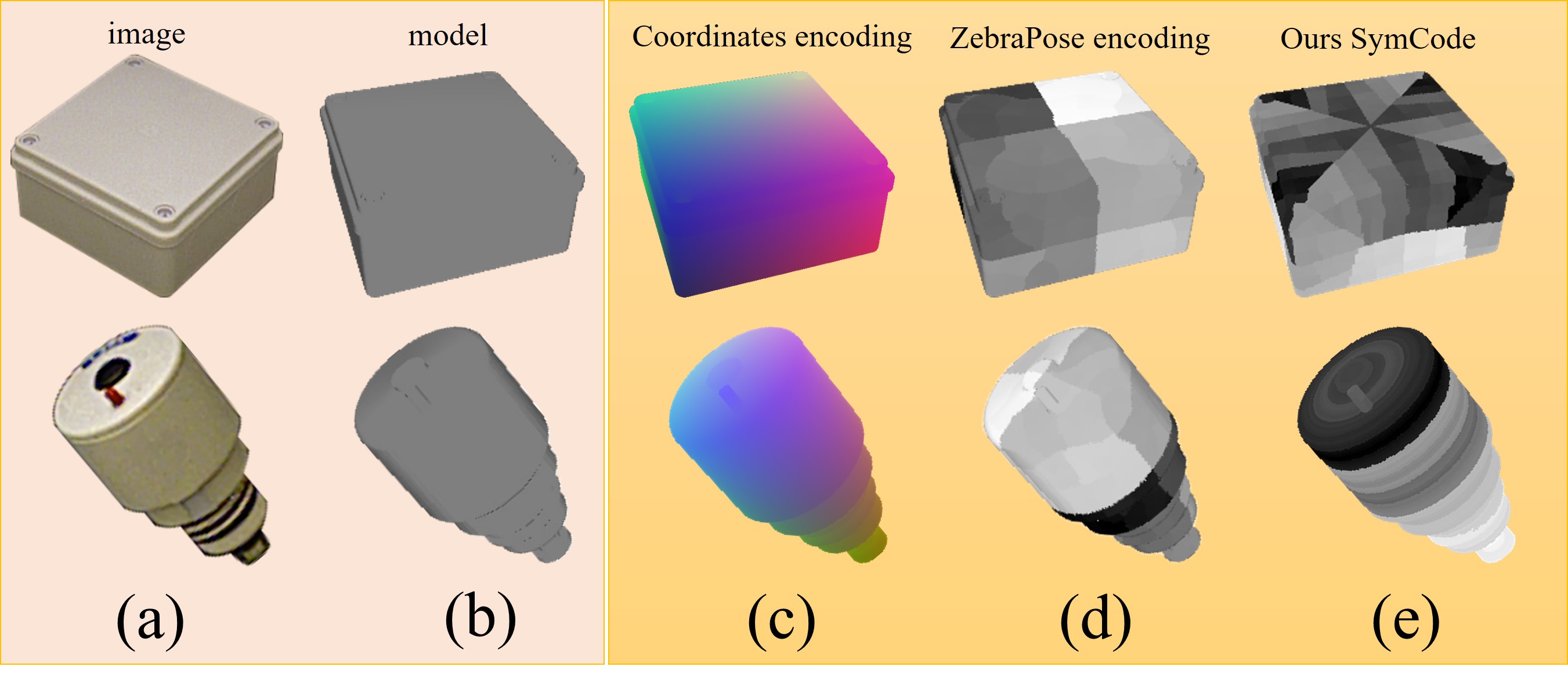
To address this issue, we propose SymCode, a dense correspondence encoding that encodes one-to-many 2D-3D correspondences, benefiting not only symmetrical objects but also objects that are ”almost symmetrical”, meaning that they exhibit symmetry to some extent but may have slight variations or irregularities that deviate from perfect symmetry. For asymmetrical objects, the one-to-many 2D-3D correspondences converge to one-to-one 2D-3D correspondences.
SymCode vs. ZebraPose Encoding. We were inspired by the surface encoding introduced in ZebraPose [5] to assign a discrete code to each correspondence, which facilitates the network training. SymCode, as shown in Figure 1, internally captures symmetry information but does not adhere to the one-to-one correspondence assumption of the PnP algorithm. A similar situation is faced by SurfEmb [8], which generates a large number of pose candidates using P3P and employs a refinement process to obtain the final pose. However, this process is time-consuming. In contrast, we introduce an end-to-end network, called SymNet, to directly output the pose from SymCode along with a segmentation mask.
To summarize, the main contributions of our work are as follows:
-
1.
We propose SymCode, a symmetry-aware binary surface encoding method that allows the estimation of one-to-many 2D-3D correspondences for pose estimation.
-
2.
We introduce SymNet, a network that recovers object pose from one-to-many 2D-3D correspondences without relying on the PnP-RANSAC method, leading to significant improvements in inference time.
-
3.
We investigate the impact of object symmetries as well as the performance of different symmetry-aware methods in correspondence-based object pose estimation through experiments on high-symmetry datasets such as T-LESS and IC-BIN.
II RELATED WORK
Symmetry or pose ambiguity refers to the phenomenon where images of an object under different poses appear identical, making it impossible to determine the object’s pose uniquely. In this section, we provide a brief overview of works that incorporate mechanisms for handling symmetries.
Pitteri [9] offers a general analytic approach to map symmetrical identities to the same pose, but results in discontinuity of the mapped pose, potentially causing abrupt changes in the network output. CosyPose [10] utilizes the symmetry-aware ADD-S loss, which measures pose accuracy by considering the closest symmetric pose of the object as ground truth. ES6D [11] categorizes symmetry into five categories and proposes a symmetry-invariant A(M)GPD loss based on these categories, which outperforms the ADD(S) loss. However, this method cannot be directly applied to correspondence-based methods.
Recent correspondence-based methods typically learn one-to-one correspondences representation as auxiliary targets. However, symmetry can introduce correspondence ambiguity, causing pixels in the image to have non-unique corresponding vertices on the model, thereby leading to pose ambiguity. [12] proposes a representation called ”closed symmetry loop” to obtain one-to-many correspondences, where information represents the angle between different points and the object origin. This information is fused to achieve one-to-one correspondence. EPOS [13] utilizes surface fragments to address symmetry and establishes one-to-many 2D-3D correspondences. However, the final pose is estimated from a sampled triplet of correspondences by the P3P solver. This approach still has some limitations in continuous symmetry for regressing 3D coordinates on fragment coordinate systems. GDR-Net [4] guides pose regression by computing the loss with respect to the closest symmetric pose and incorporates surface fragments from EPOS [13]. Surfemb [8] learns one-to-many correspondences in a self-supervised manner but samples one-to-one correspondences from the one-to-many correspondences to adapt to the RANSAC-P3P algorithm input. To the best of our knowledge, our work is the first to directly recover pose from one-to-many correspondences.
III METHOD
This section offers a comprehensive description of our proposed one-to-many correspondence-based and symmetry-aware training method for 6D object pose estimation.
We aim to address the symmetrical ambiguity issue beyond the one-to-one correspondence approach. Drawing inspiration from the successful application of binary codes in one-to-one correspondence methods [3, 5], we extend this approach to encode one-to-many correspondences, which are then fed into a network to obtain the final pose without RANSAC or the need of refinement.
III-A Problem Definition and Notation
Given an RGB image with known intrinsic parameters and a set of CAD models of objects, our objective is to estimate the pose of each object (Rotation matrix and translation vector ) with respect to the camera in the image.
There is only one ground-truth pose for an asymmetric object, while a symmetric object has multiple possible ground-truth poses , where is the number of ground-truth poses, which can be infinite.
ZebraPose [5] constructs a binary encoding of the object model vertices, that defines binary codes of bits that uniquely correspond to vertices . The binary encoding is built iteratively, by splitting the mesh into parts of equal amount of vertices at each step, and assigning a bit to each group. In the iteration of the surface partition, we have separate sub-groups. Given a group of vertices, the partitioning is carried out using balanced k-means, resulting in the formation of two sub-groups. For asymmetrical objects, the one-to-many correspondences are equivalent to the one-to-one correspondences since there is no ambiguity due to symmetry.
In the following sections, we compare one-to-one correspondences with one-to-many correspondences in detail. Subsequently, we present our approach for estimating the 6DoF object pose, which involves the entire process from surface encoding to the final pose estimation.
III-B 2D-3D Correspondences
One-to-one Correspondences Extracting one-to-one correspondences is a key component in pose estimation, which represents a match between a 2D point from the observed image and a 3D point from the object model, denoted as , where and . The correspondence can be derived based on the ground-truth pose point-wise:
| (1) |
where is the projection function of a pinhole camera model using intrinsic matrix. We define a one-to-one correspondence set containing one-to-one correspondences, where . The Perspective-n-Point (PnP) module aims to recover the pose given a set of one-to-one correspondences. Most correspondence-based methods use the one-to-one correspondence set as an intermediate geometric representation. For an asymmetric object, the one-to-one correspondence is unique and can be recovered without ambiguity, but this is not the case for symmetric objects.
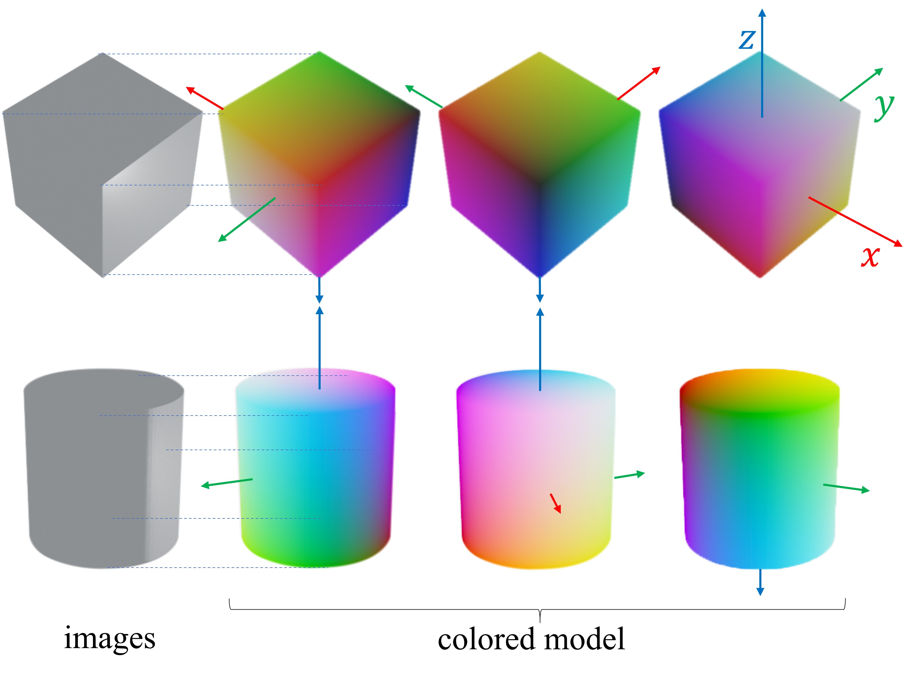
For each ground-truth pose of a symmetric object, we can obtain a one-to-one correspondence set using Equation 1. However, in the training stage, setting similar images with vastly different correspondence sets as learning targets can lead to convergence problems. We illustrate different one-to-one correspondence sets for a cube and a cylinder in Figure 2.
One-to-many Correspondence. We define a one-to-many correspondence to represent a match between a 2D point and a set of all possible 3D points , denoted as . The correspondence should satisfy the following condition:
| (2) |
are all the possible ground-truth poses. We define a one-to-many correspondence set containing one-to-many correspondences, where , as depicted in Figure 3. The one-to-many correspondence demonstrate that from a pixel , it is impossible to determine the matching 3D point coordinates , but it is possible to determine the corresponding 3D point set . The one-to-many correspondence presents an easier learning task for the network compared to the one-to-one correspondences due to its lack of ambiguity.

III-C Symmetry-aware Surface Encoding
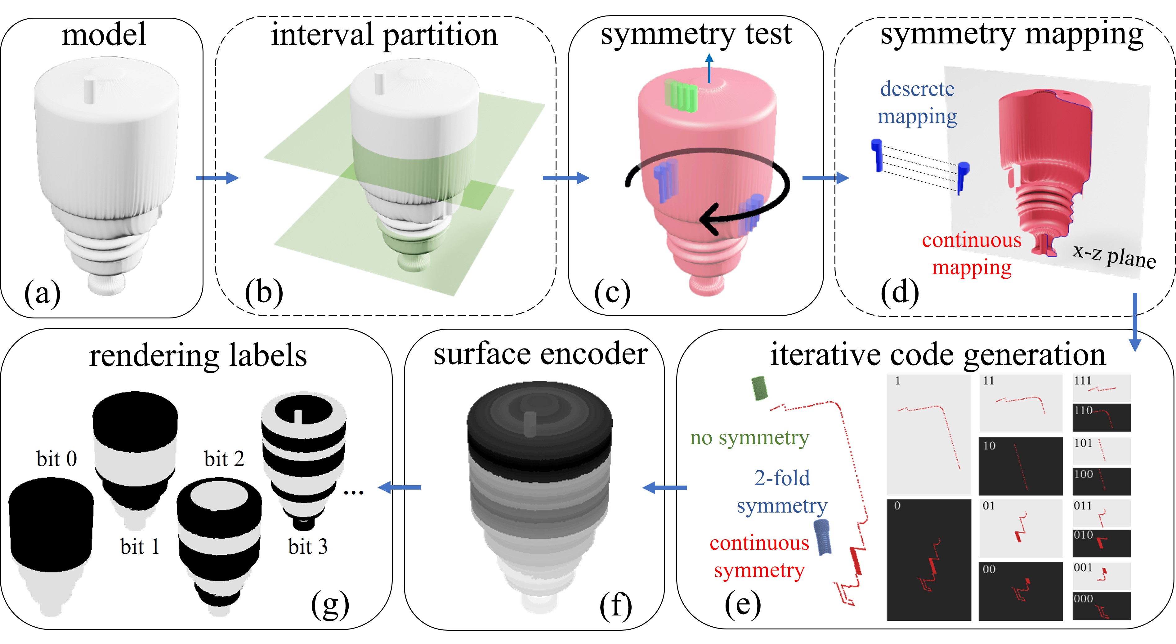
Our objective is to encode each one-to-many correspondence with a discrete binary code . Figure 4 presents a schematic overview of the proposed one-to-many surface encoding pipeline.
Generate One-to-Many Correspondence. When an object possesses symmetry, there are multiple rigid motions that can map one ground-truth pose to other ground-truth poses. Formally, we consider the set as follows:
| (3) |
where represents any single ground-truth pose, represents another ground-truth pose where denotes the total number of possible ground-truth poses.
Symmetries can be categorized into two types: discrete and continuous. In the case of discrete symmetry, the set consists of a finite number of elements. For a vertex , we generate all other possible 3D vertices belonging to the same one-to-many correspondence as
| (4) |
In the case of continuous symmetry, the vertices on the surface undergo rotation along the axis of symmetry, resulting in their alignment on a plane, as illustrated in Figure 4(d). By doing so, vertices that undergo rotation and end up at the same position on the plane are consolidated into the same correspondence. We can formalize the rotation process as follows:
| (5) |
Here, is the transferred vertex of origin vertex , and is referred to as the main vertex. represent the three components of . It is assumed that the rotation occurs along the z-axis, and the resulting plane is the x-y plane, as illustrated in Figure 4(d).
Handling Mixture Symmetry. For the T-LESS dataset, different objects are only annotated with the main type of symmetry. We can directly generate one-to-many correspondences based on this symmetry annotation. However, many objects consist of a mixture of symmetric parts. Consider an object constructed by combining a cube and a cylinder together. Although considering the entire object may suggest discrete symmetry, utilizing correspondences constructed based on discrete symmetry in occluded scenarios would still result in ambiguity.
Additionally, some objects are considered ”almost symmetrical,” meaning they exhibit symmetry except for a small detail. To tackle these challenges, we offer an advanced annotation tool that enables more precise labeling of object models. This is the only part of the process that is still manual, but can be completed within a few minutes only. If the object is perfectly symmetrical, this step is not necessary, making the entire annotation process fully automated, relying on symmetry annotation information from BOP [14].
Figure 4(a) provides an example of this scenario. We explicitly categorize points on objects into the following four categories (1) no symmetry, (2) continuous symmetry, (3) discrete symmetry, and (4) n-fold symmetry. The n-fold symmetry is a special case of discrete symmetry, i.e. the angle of symmetry is
| (6) |
along the axis. The classification is determined by the average distance between each vertex and its nearest vertex after applying the transformation in Equation 4. Since different types of symmetry inherently have an inclusion relationship, we introduce the concept of symmetry priority. This priority determines the order in which we test the symmetry type of a vertex. Specifically, we follow this priority order: discrete symmetry n-fold symmetry continuous symmetry no symmetry. The primary symmetry type is provided in the dataset’s meta information. However, for the details that break the symmetry, human intervention is required to specify them and ensure that the correct symmetry type is identified. Additionally, thresholds of error derived from empirical or experimental observations can also be used to assist in identifying the symmetry type . For a given symmetry type , we will generate the correspondence set based on that symmetry and calculate the error under this specific symmetry type as follows:
| (7) |
where refers to the nearest vertex to the transformed vertex on the object surface.
After removing the vertices that belong to high-priority symmetry, the remaining vertices can be classified into the low-priority symmetry category. Any vertices that are not categorized as belonging to any symmetry type will be recognized as having no symmetry.
In order to attain a more precise classification, the model can be subdivided into smaller intervals, enabling the identification of different forms of potential symmetry within each interval. This approach allows for a more detailed analysis of the symmetry structure, as depicted in Figure 4(b).
Encoding Correspondence. We have established the one-to-many correspondence set wherein each group comprises vertices denoted as . Additionally, each group is associated with a symmetry type . We introduce a method for encoding the one-to-many correspondence set. The object surface is encoded by incorporating a hierarchical binary grouping scheme for the one-to-many correspondence set.
The encoding indicates which corresponding group this pixel matches to. The encoding should ideally meet the following criteria: 1) To provide ample information for pose estimation, the encoding should exhibit significant differences for two groups and with distinct symmetry types. 2) To facilitate easier learning for the network, correspondences that are in close proximity should have more similar encodings. 3) Each corresponds to a unique encoding. In general, we select one 3D vertex, referred to as the main vertex, from each correspondence while considering the spatial proximity of neighboring correspondences. The main vertex will be utilized for implementing binary encoding in the next step.
Next, we introduce how to obtain the main vertex for each correspondence. For correspondences exhibiting continuous symmetry, we select the vertex mapped to the plane as the main vertex using Equation 5. For other types of symmetry, we select the main vertex based on a simple criterion explained below, which can be replaced with alternative approaches as long as it satisfies the criteria (2). In our implementation, the used criterion calculates the sum of the absolute values of each coordinate component for each vertex in the correspondence. The main vertex, denoted as , is then chosen according to the equation:
| (8) |
As illustrated in Figure 4(e), the main vertices for this object are represented by the colored vertices. Only one vertex in the correspondence is not symmetrical, which will be the main vertex, colored green. For continuous symmetry, the main vertex, colored red, lies on the plane calculated by Equation 5. Regarding 2-fold symmetry, the vertices on the portion with higher coordinate values will serve as the main vertices, colored blue.
Iterative code generation. This part is inspired by the binary encoding used in the one-to-one correspondence method [5]. Given the one-to-many correspondences set, we want to represent each correspondence with a binary code , where is the length of the binary code. We construct such encodings based on the main vertex of each correspondence.
In Figure 4(e), we illustrate the process of performing iterations of grouping the main vertices. The grouping iteration begins with collections of all main vertices . For a group with a binary code , we divide it into two groups using k-means. The resulting groups are assigned codes and , where the operation denotes binary left shift. Eventually, we obtain groups, each with its binary code. These binary codes can be represented in decimal form from to . The surface encoder is depicted in Figure 4(f), where the color represents the decimal value of the binary code .
III-D Network Architecture
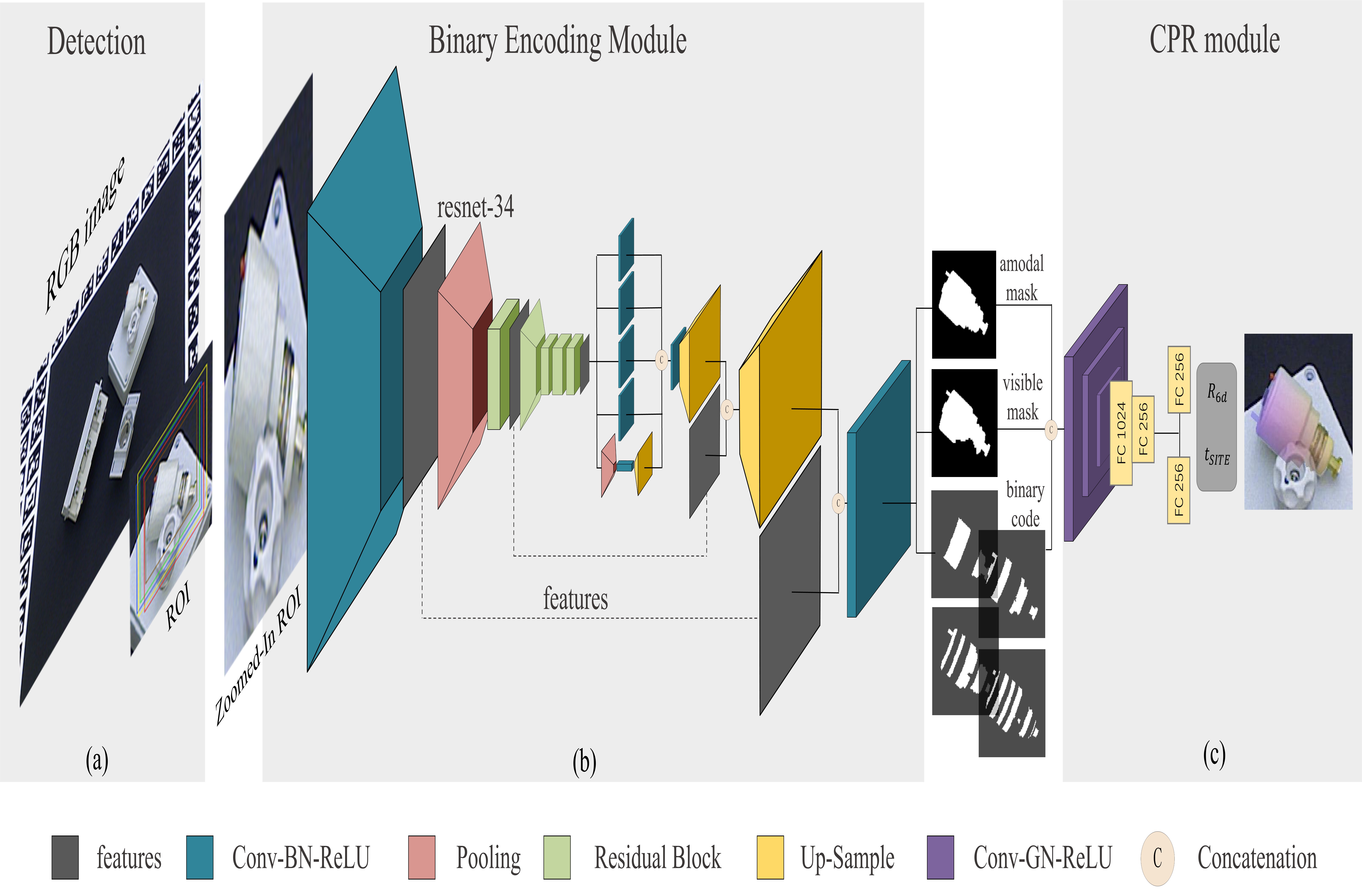
In Figure 5, we provide the Binary Encoding Module with a zoomed-in region of interest (RoI). The outputs, namely the amodal mask , visible mask , and SymCode maps , serve as intermediate variables. Subsequently, these intermediate variables are utilized as inputs to the Correspondence-based Pose Regression (CPR) module.
Our network is inspired by ZebraPose [5] and GDR-Net [4]. We utilize a straightforward Correspondence-based Pose Regression (CPR) module to directly regress the 6D pose from the visible mask , amodal mask , and SymCode maps . The CPR module comprises three convolutional layers, each followed by Group Normalization and ReLU activation. Subsequently, two fully connected layers are applied to the flattened features. Finally, two parallel fully connected layers output the 3D rotation parameterized as [15] and the 3D translation parameterized as [16], respectively.
We utilize loss for both the visible mask, amodal mask and SymCode maps. Our training loss is defined as
| (9) |
corresponds to the loss for end-to-end training utilizes the loss for and . Additionally, the term is derived from the work of [17].
IV EXPERIMENTS
In this section, we introduce evaluation metrics and briefly introduce a symmetry-aware version of [5] - ZebraPoseSAT, then compare our method with other model-based approaches on the T-LESS [18] and IC-BIN [19] datasets. These datasets encompass a variety of symmetric objects, while a large synthetic-to-real domain gap exists because of texture mismatch. This makes T-LESS and IC-BIN particularly suitable for evaluating the performance of methods on symmetric objects. Furthermore, we present ablation experiments on various hyperparameters and visualizations to intuitively demonstrate the impact of SymCode.
IV-A Evaluation Protocol
The Visible Surface Discrepancy (VSD) evaluates the proportion of visible pixels for which the depth absolute discrepancy falls below a threshold of . We report the recall of correct 6D object poses at [9]. We also adhere to the evaluation protocol outlined in the BOP challenge [14] using three metrics: Visible Surface Discrepancy (VSD), Maximum Symmetry-aware Surface Distance (MSSD), and Maximum Symmetry-aware Projection Distance (MSPD).
IV-B ZebraPoseSAT: Alternative Symmetry-aware Solution
To provide an symmetry-aware version of ZebraPose [5] for comparison, we additionally implement ZebraPoseSAT (SAT standing for Symmetry-Aware Training), which utilizes an analytical approach [9] to map all ground truth poses to a unique based on the Froebenius norm, prior to generating ZebraPose Encoding. ZebraPoseSAT emerged as the winner of the Best RGB-Only Method in the BOP 2023 challenge [14], providing a strong comparison baseline for SymNet.
IV-C Comparison to State of the Art
| Method | AAE [20] | Pix2Pose [21] | EdgeEnhance [22] | Pitteri[9] | CosyPose[10] | Ours(pbr) | Ours(pbr+real) | |
| Detector | SSD | Retina | Retina | Retina | Faster-RCNN | Retina | FCOS(pbr) | FCOS(pbr+real) |
| Symmetry type | RGB | RGB | RGB | RGB | RGB | RGB-D | RGB | RGB |
| Asymmetry (3) | 25.98 | 16.95 | 24.73 | 28.76 | 36.533 | - | 66.36 | 69.47 |
| Continuous (11) | 11.90 | 17.98 | 36.27 | 39.05 | 46.65 | - | 61.52 | 63.72 |
| Discrete (16) | 14.45 | 18.86 | 25.79 | 32.77 | 38.47 | - | 69.51 | 78.02 |
| Mean | 14.67 | 18.35 | 29.5 | 34.67 | 41.27 | 62.6 | 66.27 | 71.92 |
Results on T-LESS. Symmetry-related works generally report the recall score in the T-LESS dataset. In Table I, SymNet achieves an impressive improvement of over the results reported by Pitteri [9]. As the Retina detector code is outdated and the detection results are not publicly available, we made use of the FCOS [23] detector as an alternative. For pair comparison, we also included results from CosyPose [10], which also provides BOP scores and recall simultaneously. The objects of T-LESS are grouped in 3 categories based on their symmetry type and we provide the average scores for all objects in each category.
| 6D object pose estimation method | Input type | Training type | Time(s) | ||||
| CDPNv2 [16] | RGB | pbr | 0.407 | 0.303 | 0.338 | 0.579 | 1.849 |
| CosyPose [10] | RGB | pbr | 0.640 | 0.571 | 0.589 | 0.761 | 0.493 |
| EPOS [13] | RGB | pbr | 0.467 | 0.380 | 0.403 | 0.619 | 1.992 |
| ZebraPose [5] | RGB | pbr | 0.677 | 0.597 | 0.636 | 0.466 | 0.25 |
| ZebraPoseSAT-EffnetB4 | RGB | pbr | 0.723 | 0.659 | 0.695 | 0.817 | 0.25 |
| SurfEmb [8] | RGB | pbr | 0.735 | 0.661 | 0.686 | 0.857 | 9.043 |
| SymNet(Ours) | RGB | pbr | 0.736 | 0.631 | 0.693 | 0.883 | 0.093 |
| DPODv2 [24] | RGB-D | pbr | 0.699 | 0.646 | 0.716 | 0.736 | 0.320 |
| ZebraPose [5] | RGB | real+pbr | 0.775 | 0.696 | 0.740 | 0.889 | 0.25 |
| SymNet(Ours) | RGB | real+pbr | 0.767 | 0.674 | 0.739 | 0.883 | 0.058 |
Results on BOP Benchmark.
We compare our results to other methods that are fully trained on synthetic data, as shown in Table II and Table III. We use the default detections provided by BOP challenge 2023 [14]. Since our method does not rely on a time-consuming pose refinement step and directly obtains the pose for every detection, our runtime is significantly reduced compared to the other methods. Our method achieves excellent results in terms of both accuracy and runtime. Specifically, our results match the accuracy of ZebraposeSAT-EffnetB4 but with a smaller backbone, and only at one third of the runtime.
| 6D object pose estimation method | Input type | Training type | Time(s) | ||||
| CRT-6D [25] | RGB | pbr | 0.537 | 0.477 | 0.517 | 0.618 | 0.120 |
| ZebraPoseSAT-EffnetB4 | RGB | pbr | 0.545 | 0.475 | 0.535 | 0.625 | 0.25 |
| SymNet(Ours) | RGB | pbr | 0.547 | 0.450 | 0.511 | 0.678 | 0.088 |
IV-D Ablation Studies
| CPR | EPnP | ||||
| ✓ | 0.283 | 0.166 | 0.190 | 0.493 | |
| ✓ | 0.736 | 0.631 | 0.693 | 0.883 |
Compare with PnP solver. In Table IV, we demonstrate the effectiveness of our CPR module. We compare the performance of our CPR module with that of RANSAC/PnP [6]. The results reveal that using PnP alone is challenging in terms of obtaining accurate correspondences, which are crucial for achieving reliable pose estimation. On the other hand, our CPR module is capable of accurately calculating the final pose.
Compare with ZebraPose. Due to the limitation of one-to-one correspondence, we initially assumed that ZebraPose would not perform well on symmetrical objects. However, in the BOP benchmark, we observe that ZebraPose achieves a satisfactory average recall score of 0.775, which is higher than our result of 0.767 when trained with real data. We attribute this to the utilization of real images during training. Since most objects are not perfectly symmetrical, the network trained with real data can capture subtle variations and mitigate the symmetry problem. The results we can access are specifically for the model with a larger backbone, referred to as ZebraPoseSAT-EffnetB4, which has been trained solely on PBR data. However, the results for the ZebraPose model trained exclusively on PBR data are not publicly available. We performed the experiment ourselves using open-source project code, and the average recall score is . In the same setting, our score exhibits improvements in both accuracy and inference time.
Length of SymCode. The default setting of length for is as used in ZebraPose [5]. We investigate the impact of varying on the training process, as illustrated in Figure 6. The results indicate that our approach is robust to variations in the length of the binary code. Indeed, the accuracy achieved with different values of can be unpredictable, and there is no clear way to determine an optimized value beforehand. As a result, in our main results, we have chosen to fix the length of the binary code to the default value of .

Challenge of learning one-to-one correspondences. We conducted experiments involving training our end-to-end network using ZebraPose encodings, which is an efficient way to encode one-to-one correspondences. In this case, the network achieved a BOP recall of 0.612, which is relatively weaker compared to SymNet’s performance of 0.736. When we removed all the end-to-end loss and focused solely on training the ZebraPose encodings, Figure 7 illustrates the challenges associated with learning one-to-one correspondence-based encodings.
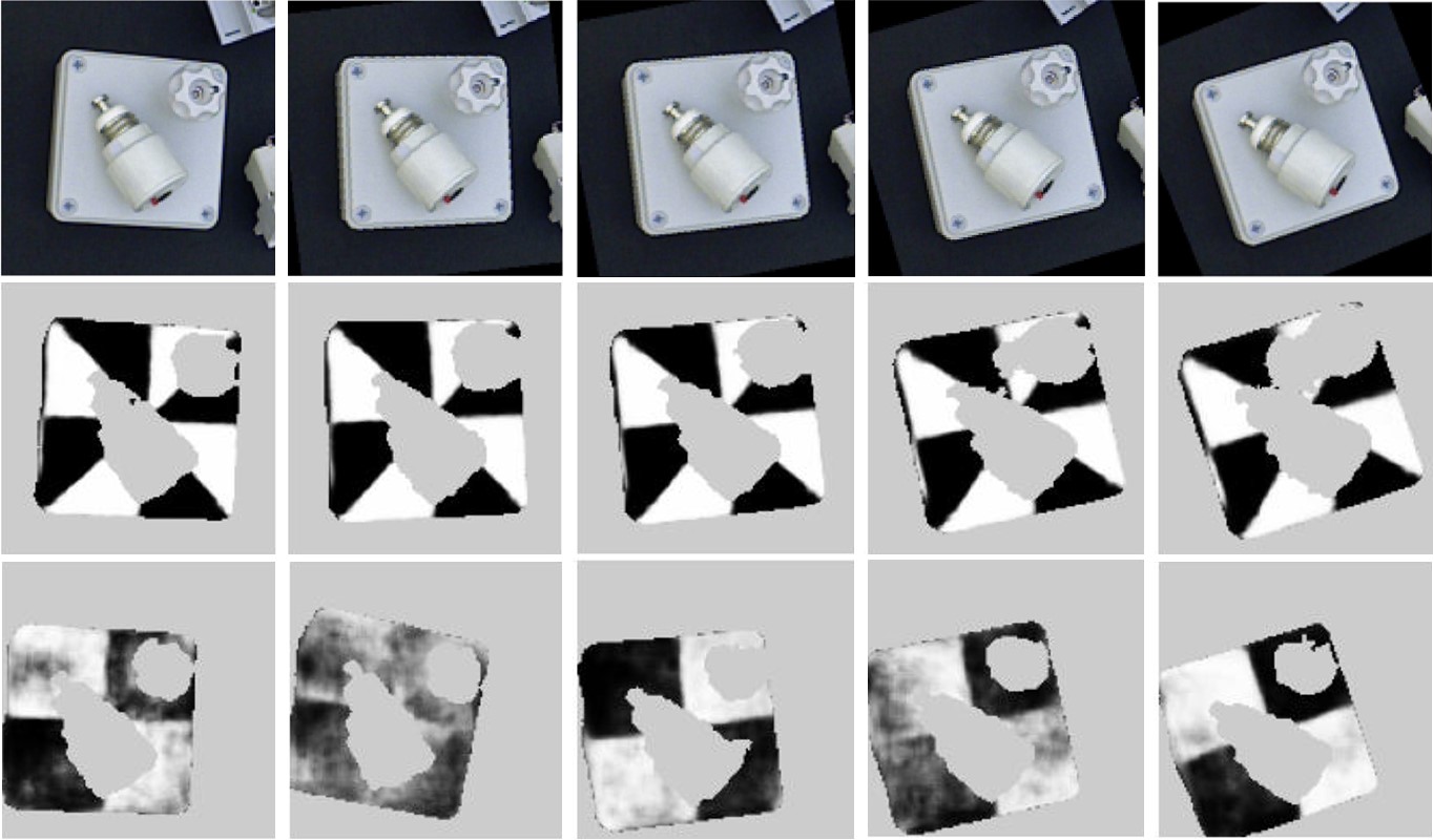
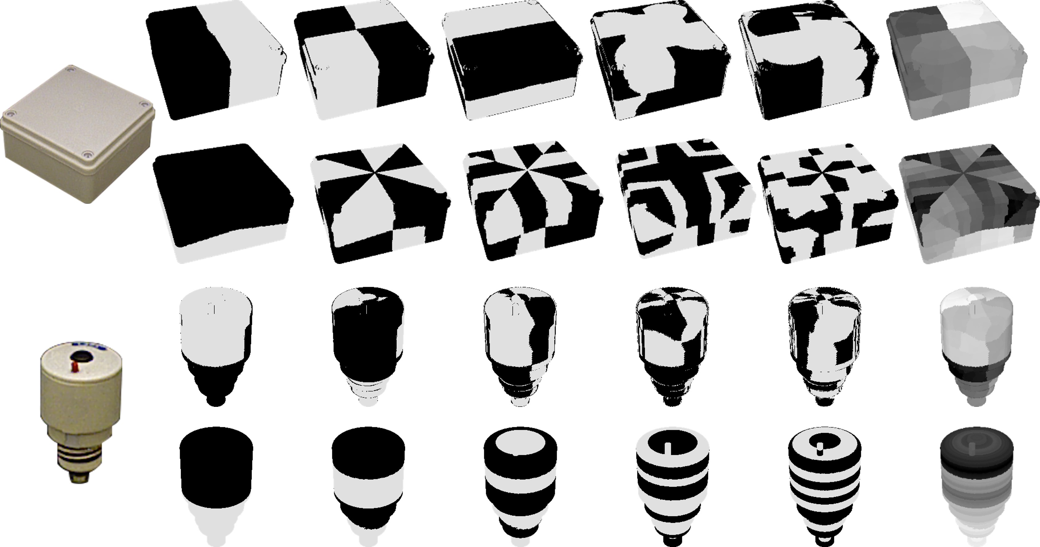
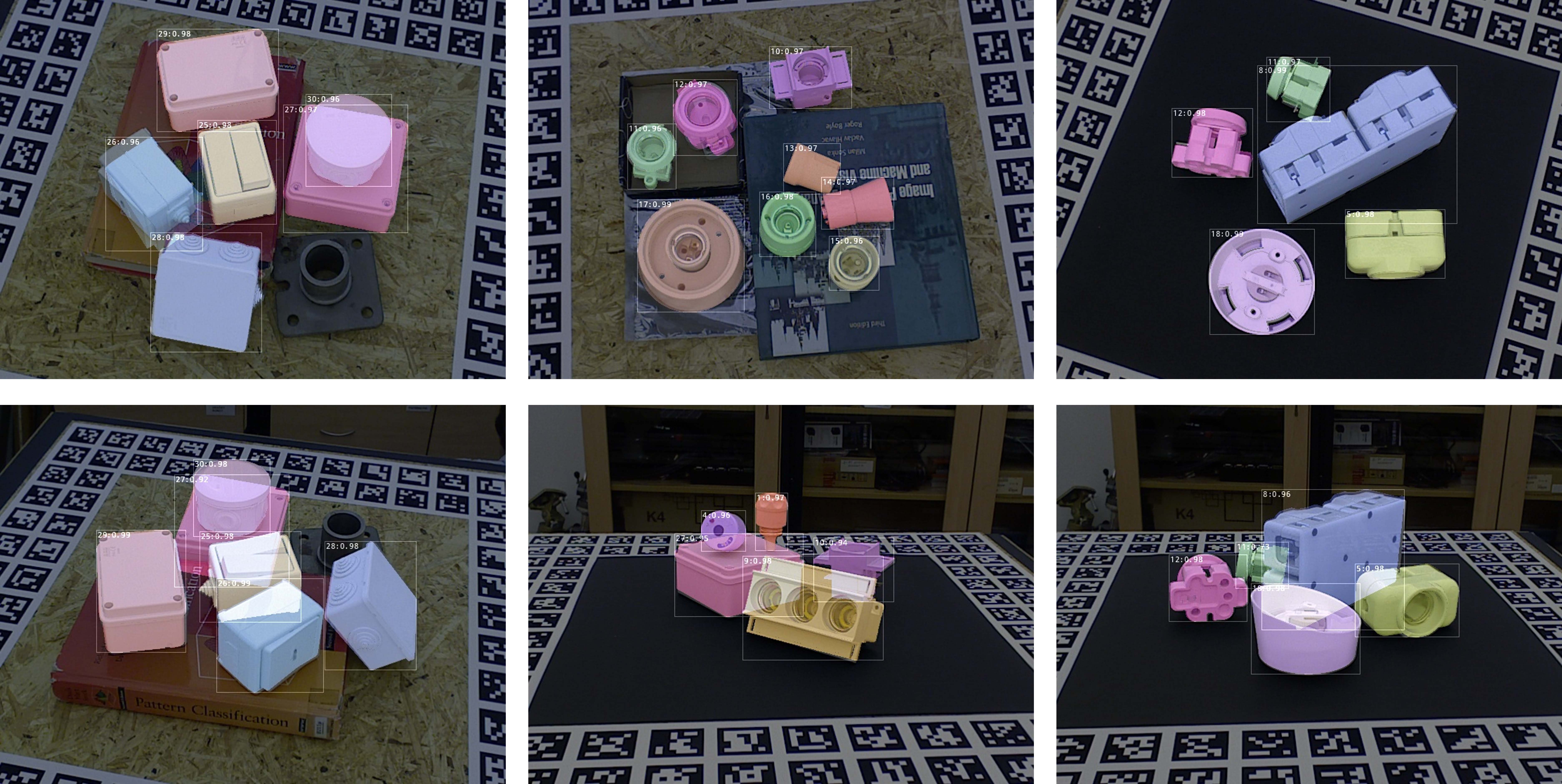
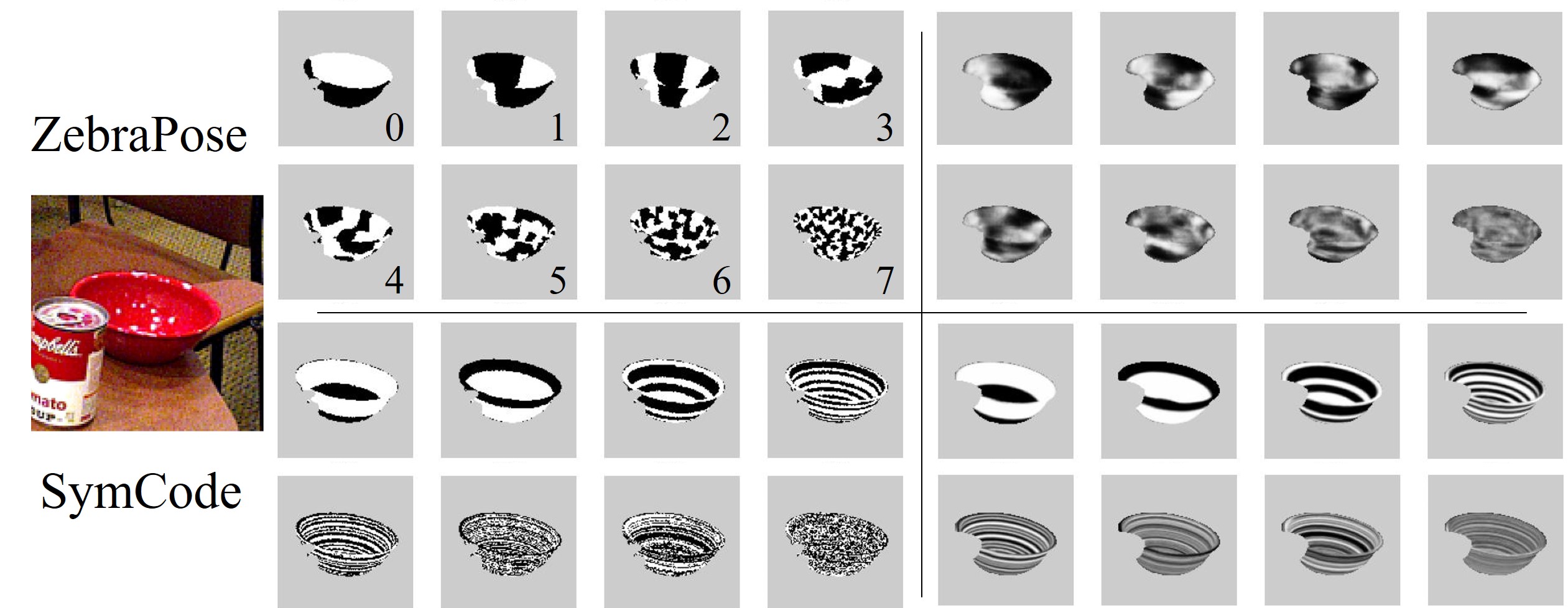
Visualization. Detailed binary code maps representing SymNet and ZebraPose are visualized in Figure 8, which shows our binary codes contain symmetry information. Qualitative results on T-LESS [18] can be found in Figure 9. A visual representation of the ground truth and predicted code maps for ZebraPose and Symnet show in Figure 10. From the visualization, it is evident that ZebraPose struggles to accurately reproduce the ground truth, whereas Symnet exhibits better performance in this regard.
V CONCLUSION
Our method incorporates a symmetry discrete surface encoding technique to effectively handle symmetries. Furthermore, we demonstrate the ability to recover the pose from one-to-many 2D-3D correspondences. This approach holds the potential to influence not only other correspondence-based methods but also various other fields related to pose estimation.
References
- [1] Y. Su, J. Rambach, N. Minaskan, P. Lesur, A. Pagani, and D. Stricker, “Deep multi-state object pose estimation for augmented reality assembly,” in 2019 IEEE International Symposium on Mixed and Augmented Reality Adjunct (ISMAR-Adjunct). IEEE, 2019, pp. 222–227.
- [2] Y. Su, Y. Di, G. Zhai, F. Manhardt, J. Rambach, B. Busam, D. Stricker, and F. Tombari, “Opa-3d: Occlusion-aware pixel-wise aggregation for monocular 3d object detection,” IEEE Robotics and Automation Letters, vol. 8, no. 3, pp. 1327–1334, 2023.
- [3] Y. Lin, Y. Su, P. Nathan, S. Inuganti, Y. Di, M. Sundermeyer, F. Manhardt, D. Stricker, J. Rambach, and Y. Zhang, “Hipose: Hierarchical binary surface encoding and correspondence pruning for RGB-d 6dof object pose estimation,” in Conference on Computer Vision and Pattern Recognition 2024, 2024.
- [4] G. Wang, F. Manhardt, F. Tombari, and X. Ji, “Gdr-net: Geometry-guided direct regression network for monocular 6d object pose estimation,” in Proceedings of the IEEE/CVF Conference on Computer Vision and Pattern Recognition, 2021, pp. 16 611–16 621.
- [5] Y. Su, M. Saleh, T. Fetzer, J. Rambach, N. Navab, B. Busam, D. Stricker, and F. Tombari, “Zebrapose: Coarse to fine surface encoding for 6dof object pose estimation,” in Proceedings of the IEEE/CVF Conference on Computer Vision and Pattern Recognition, 2022, pp. 6738–6748.
- [6] Vincent, Lepetit, Francesc, Moreno-NoguerPascal, and Fua, “Epnp: An accurate o(n) solution to the pnp problem,” International Journal of Computer Vision, 2009.
- [7] Y. Di, F. Manhardt, G. Wang, X. Ji, N. Navab, and F. Tombari, “So-pose: Exploiting self-occlusion for direct 6d pose estimation,” in Proceedings of the IEEE/CVF International Conference on Computer Vision, 2021, pp. 12 396–12 405.
- [8] R. L. Haugaard and A. G. Buch, “Surfemb: Dense and continuous correspondence distributions for object pose estimation with learnt surface embeddings,” in Proceedings of the IEEE/CVF Conference on Computer Vision and Pattern Recognition, 2022, pp. 6749–6758.
- [9] G. Pitteri, M. Ramamonjisoa, S. Ilic, and V. Lepetit, “On object symmetries and 6d pose estimation from images,” in 2019 International conference on 3D vision (3DV). IEEE, 2019, pp. 614–622.
- [10] Y. Labbé, J. Carpentier, M. Aubry, and J. Sivic, “Cosypose: Consistent multi-view multi-object 6d pose estimation,” in Computer Vision–ECCV 2020: 16th European Conference, Glasgow, UK, August 23–28, 2020, Proceedings, Part XVII 16. Springer, 2020, pp. 574–591.
- [11] N. Mo, W. Gan, N. Yokoya, and S. Chen, “Es6d: A computation efficient and symmetry-aware 6d pose regression framework,” in Proceedings of the IEEE/CVF Conference on Computer Vision and Pattern Recognition, 2022, pp. 6718–6727.
- [12] J. Richter-Klug and U. Frese, “Handling object symmetries in cnn-based pose estimation,” in 2021 IEEE International Conference on Robotics and Automation (ICRA). IEEE, 2021, pp. 13 850–13 856.
- [13] T. Hodan, D. Barath, and J. Matas, “Epos: Estimating 6d pose of objects with symmetries,” in Proceedings of the IEEE/CVF conference on computer vision and pattern recognition, 2020, pp. 11 703–11 712.
- [14] T. Hodan, M. Sundermeyer, Y. Labbe, V. N. Nguyen, G. Wang, E. Brachmann, B. Drost, V. Lepetit, C. Rother, and J. Matas, “Bop challenge 2023 on detection, segmentation and pose estimation of seen and unseen rigid objects,” arXiv preprint arXiv:2403.09799, 2024.
- [15] Y. Zhou, C. Barnes, J. Lu, J. Yang, and H. Li, “On the continuity of rotation representations in neural networks,” in Proceedings of the IEEE/CVF Conference on Computer Vision and Pattern Recognition, 2019, pp. 5745–5753.
- [16] Z. Li, G. Wang, and X. Ji, “Cdpn: Coordinates-based disentangled pose network for real-time rgb-based 6-dof object pose estimation,” in Proceedings of the IEEE/CVF International Conference on Computer Vision, 2019, pp. 7678–7687.
- [17] Y. Xiang, T. Schmidt, V. Narayanan, and D. Fox, “Posecnn: A convolutional neural network for 6d object pose estimation in cluttered scenes,” 2018.
- [18] T. Hodan, P. Haluza, S. Obdrzalek, J. Matas, M. Lourakis, and X. Zabulis, “T-less: An rgb-d dataset for 6d pose estimation of texture-less objects,” IEEE, 2017.
- [19] A. Doumanoglou, R. Kouskouridas, S. Malassiotis, and T. Kim, “Recovering 6d object pose and predicting next-best-view in the crowd,” in 2016 IEEE Conference on Computer Vision and Pattern Recognition (CVPR). Los Alamitos, CA, USA: IEEE Computer Society, jun 2016, pp. 3583–3592.
- [20] M. Sundermeyer, Z.-C. Marton, M. Durner, M. Brucker, and R. Triebel, “Implicit 3d orientation learning for 6d object detection from rgb images,” in Proceedings of the european conference on computer vision (ECCV), 2018, pp. 699–715.
- [21] K. Park, T. Patten, and M. Vincze, “Pix2pose: Pixel-wise coordinate regression of objects for 6d pose estimation,” in Proceedings of the IEEE/CVF International Conference on Computer Vision, 2019, pp. 7668–7677.
- [22] Y. Wen, H. Pan, L. Yang, and W. Wang, “Edge enhanced implicit orientation learning with geometric prior for 6d pose estimation,” IEEE Robotics and Automation Letters, vol. 5, no. 3, pp. 4931–4938, 2020.
- [23] Z. Tian, C. Shen, H. Chen, and T. He, “Fcos: Fully convolutional one-stage object detection,” in Proceedings of the IEEE/CVF International Conference on Computer Vision (ICCV), October 2019.
- [24] I. Shugurov, S. Zakharov, and S. Ilic, “Dpodv2: Dense correspondence-based 6 dof pose estimation,” IEEE transactions on pattern analysis and machine intelligence, vol. 44, no. 11, pp. 7417–7435, 2021.
- [25] P. Castro and T.-K. Kim, “Crt-6d: Fast 6d object pose estimation with cascaded refinement transformers,” in Proceedings of the IEEE/CVF Winter Conference on Applications of Computer Vision, 2023, pp. 5746–5755.