VascularPilot3D: Toward a 3D fully autonomous navigation for endovascular robotics
Abstract
This research reports VascularPilot3D, the first 3D fully autonomous endovascular robot navigation system. As an exploration toward autonomous guidewire navigation, VascularPilot3D is developed as a complete navigation system based on intra-operative imaging systems (fluoroscopic X-ray in this study) and typical endovascular robots. VascularPilot3D adopts previously researched fast 3D-2D vessel registration algorithms and guidewire segmentation methods as its perception modules. We additionally propose three modules: a topology-constrained 2D-3D instrument end-point lifting method, a tree-based fast path planning algorithm, and a prior-free endovascular navigation strategy. VascularPilot3D is compatible with most mainstream endovascular robots. Ex-vivo experiments validate that VascularPilot3D achieves success rate among 25 trials. It reduces the human surgeon’s overall control loops by . VascularPilot3D is promising for general clinical autonomous endovascular navigations.
I Introduction
Robot-assisted Endovascular Image-Guided Interventions (EIGIs) are gaining popularity in contrast to conventional regular EIGIs in treating heart disease, cancer, stroke, or neurovascular disease due to their lower mortality rate, faster recovery, and most importantly, limited exposure to radiation for surgeons. Existing robot-assisted EIGIs follow the master-slave robot operation system and are manipulated manually by surgeons for guidewire/catheter navigation and other operation procedures. Pre-operative Computed Tomography (CT) or Computed Tomography Angiography (CTA) and intra-operative fluoroscopic X-ray or Digitally Subtracted Angiograms (DSA) serve as maps and eyes for surgeons’ navigation tasks. In clinical applications, hand-operated navigation is laborious for surgeons because humans have difficulty adapting to multi-modal data, soft-tissues’ deformation, non-isometric friction, and incompatibility of control panels. Therefore, this work proposes the first 3D fully autonomous endovascular navigation system VascularPilot3D, under intra-operative (fluoroscopic X-ray in this study) and pre-operative data (CTA in this study). VascularPilot3D aims to reduce time consumption and the mental and physical burden placed on the operators in navigation procedures, allowing more focus on the clinical aspects.
Existing autonomous endovascular robots navigated instruments through intelligent agents which were trained with Reinforcement Learning (RL) [1, 2, 3, 4, 5, 6, 7, 8]. Among these RL-based studies, [2, 3, 4, 6] adopted imitation learning to make full use of human experiences while others were fully unsupervised. These works were trained and tested on phantoms except [1] whose “haptic vision” setup falls out of this article’s scope. It should be pointed out that clinical applications of these RL-based approaches require a massive amount of training on phantoms or patients, and generalization capability across different patients is unknown. More importantly, all these works were conducted on 2D dimensions, which suffered from topological ambiguity. Some trafficable intersections on 2D images were illusions from non-intersect overlapping 3D vessels. Thus, a prior-free 3D navigation method may overcome topological ambiguity and avoid expensive or even inaccessible RL-based training.
This research proposes VascularPilot3D as the first 3D prior-free autonomous endovascular navigation system. It follows the typical autonomous driving’s “mapping-localization-navigation” workflow, where “mapping” builds the full 3D vascular from pre-operative data, “localization” localizes instruments intra-operatively, “navigation” plans the global route, and makes local sequential controls. Among them, “mapping” and “localization” methods have been widely analyzed. Massive amount of studies have shown that 3D U-Net like Deep Neural Networks (DNNs) [9, 10, 11, 12, 13, 14, 15, 16] and graph convolution network [17, 18, 19] achieve satisfying and robust 3D vessel “mapping”. Meanwhile, “localization” can be realized by combining fast 2D instrument segmentation and 3D-2D vessel registration. 2D instrument segmentation, similar to 3D vessel segmentation, is developed taking the off-the-shelf lightweight U-Net DNN. Prior-free fast 3D-2D vessel registration algorithms [20, 21, 22, 23, 24] has also been well studied.
Our VascularPilot3D leverages previous algorithms for “mapping” and “localization” and enhances the localization with 3D topology constraints. More importantly, a newly proposed prior-free “navigation” module achieves efficient global path planning by treating the vessel as a tree data structure with parent pointers. We additionally propose a strategy for making controls. Our contributions include:
-
•
To our knowledge, VascularPilot3D is the first 3D prior-free autonomous endovascular navigation system. 3D navigation overcomes the false intersection problem in conventional 2D navigation works.
-
•
A novel topology-constrained instrument end point 2D to 3D registration method is proposed.
-
•
A tree-based map presentation and global path planning method is proposed. A practical control strategy is also developed for fast navigation.
-
•
Ex-vivo experiments demonstrate that VascularPilot3D consumes less control loops than human operators and achieves success rate among 25 trials.
II Methodology
II-A System overview
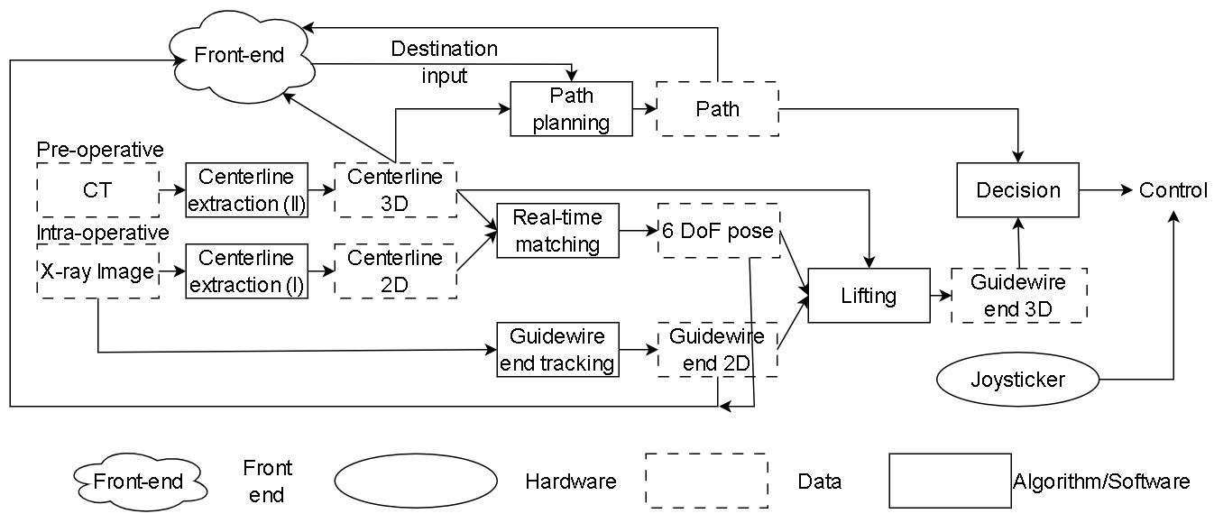
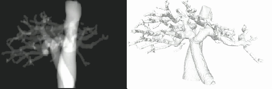
Fig. 1 shows the framework of VascularPilot3D. “Centerline extraction (I)” yields intra-operative 2D vessel centerlines in real-time from X-ray images. “Centerline extraction (II)” extracts 3D vessel centerlines from the pre-operative data before the operation. Then, a real-time 3D-2D registration is performed to match 3D and 2D vessels. Meanwhile, a lightweight DNN is applied to estimate the endpoint position of the instrument (guidewire in this study). With the correct 3D-2D registration, the endpoint is lifted from 2D to 3D space with the correct topology. Finally, a path is planned from the latest 3D endpoint position to the target 3D point in the path planning phase. VascularPilot3D then makes iterative control based on the estimated endpoint’s 3D position from the latest obtained intra-operative 2D image.
II-B Centerline segmentation and 3D-2D registration
This work strictly follows [24] for 3D and 2D centerline segmentation as well as non-rigid registration, and we briefly introduce the procedure here. Widely used Otsu’s method [25] was applied for fast 2D vessel segmentation. A DNN-based method from commercial software was used for 3D vessel segmentation. It should be emphasized that other prior-based DNNs [19, 26] are also applicable for 3D/2D image segmentation. Based on the segmented 3D and 2D centerlines, registration (optimal rigid and nonrigid transformation) was achieved by jointly maximizing Reproducing Kernel Hilbert Space (RKHS) sum constrained by regularization as
| (1) | ||||
where is the set of 3D centerline point (in homogeneous coordinate and the same applies to the rest), is the set of corresponding 2D point , is the initial pose or pose in previous state and , , , , , are hyperparameters, and (last dimension is fiexed to ) is the deformation parameter, is the camera intrinsic matrix following pin-hole camera. defines the distance on manifold and converts Lie algebra to 6-vector . is used to avoid scale drift. In the first step of minimization, is initialized as the maximum and shrinked by half every 5 iterations. This work follows the latest progress [27] and adopts the Iterative Reweighted Least Squares (IRLS) combined with Levenberg–Marquardt for fast optimization.
II-C Instrument endpoint estimation and 2D to 3D endpoint lifting
During the operation, real-time continuous X-ray images are obtained, and instrument’s 2D endpoint can be estimated with UNet like DNN methods. SA-UNet [28], first built for segmenting retinal vessels, is adopted for instrument segmentation as it achieves state-of-the-art performance on limited training data in curve-like segmentation scenario. [29]’s skeletonization method is applied to instrument mask extraction due to its efficiency and accuracy. Then, the skeleton points that have one adjacent are presumed to be candidate endpoints. The surgeons must manually choose the endpoint if more than one is found in the first frame; the selected endpoint is then adopted as the seed for iterative tracking.
With the real-time 3D-2D alignment discussed in Section II-B and 2D endpoint tracking, the estimated 2D endpoint is then lifted to 3D in pre-operative vessel’s coordinate. Although computer vision community agrees that lifting 2D to 3D is ambiguous in viewing direction, we overcome the issue using vessel registration constraints. Since the 3D endpoint and its 2D projection are all within the vessel, the 2D endpoint is lifted to 3D space via its closest 2D vessel point and the 2D vessel point’s corresponding 3D vessel point. It is obvious that the 3D localization accuracy depends on the registration and vessel radius.
II-D Global and local path planning
Previous 2D navigation methods’ global and local path planning modules [1, 2, 3, 4, 5, 6, 7, 8] cannot identify and handle false 2D intersections, as illustrated in Fig. 2. Moreover, [7, 6, 5, 4, 3] pointed out that the state presented in absolute 2D position makes the trained network difficult to be generalized. We agree with [7] that the agent “learns the movements to navigate this specific geometry”. Therefore, this research unifies global and local path planning on 3D space to circumvent false intersections and enable more generalized navigation.
Global path planning, or the route from start position to target position, is done on the 3D map in the multiway trees data structure. To fasten the search procedure, each node in the multiway trees have an additional pointer to their parent. During global path planning, the 3D endpoint position (in Section II-C) is the start point, and the surgeon chooses the 3D target position. The route is then efficiently built by tracing both nodes to their common parent in the multiway trees. This achieves the time complexity as .
Local path planning, or control, refers to sending instrument translation and rotation motion control to the slave machines. Although existing RL-based methods achieve successful navigation through iterative RL training, applying RL to 3D navigation should solve the following obstacles considering hardware, cost, and ethics: fast convergence in the phantom training process, fast adaptation across modals, efficient inference, and uncertainties. Uncertainties, mainly caused by unreliable localization, hardware control in nonrigid and nonisometric friction, and system delay, bring unpredictable phenomena in obtaining the correct control. Our experiments reveal that RL behaves well in a virtual environment and deteriorates significantly in real-world phantom. Thus, we gave up the previous RL roadmap and sought a prior-free strategy-based method. Inspired by surgeon’s “trial-and-error” in their routine endovascular navigation tasks [30, 31], VascularPilot3D summarized the process and transplanted the experience as a simple yet effective strategy as shown in Algorithm 1.
III Results and discussion
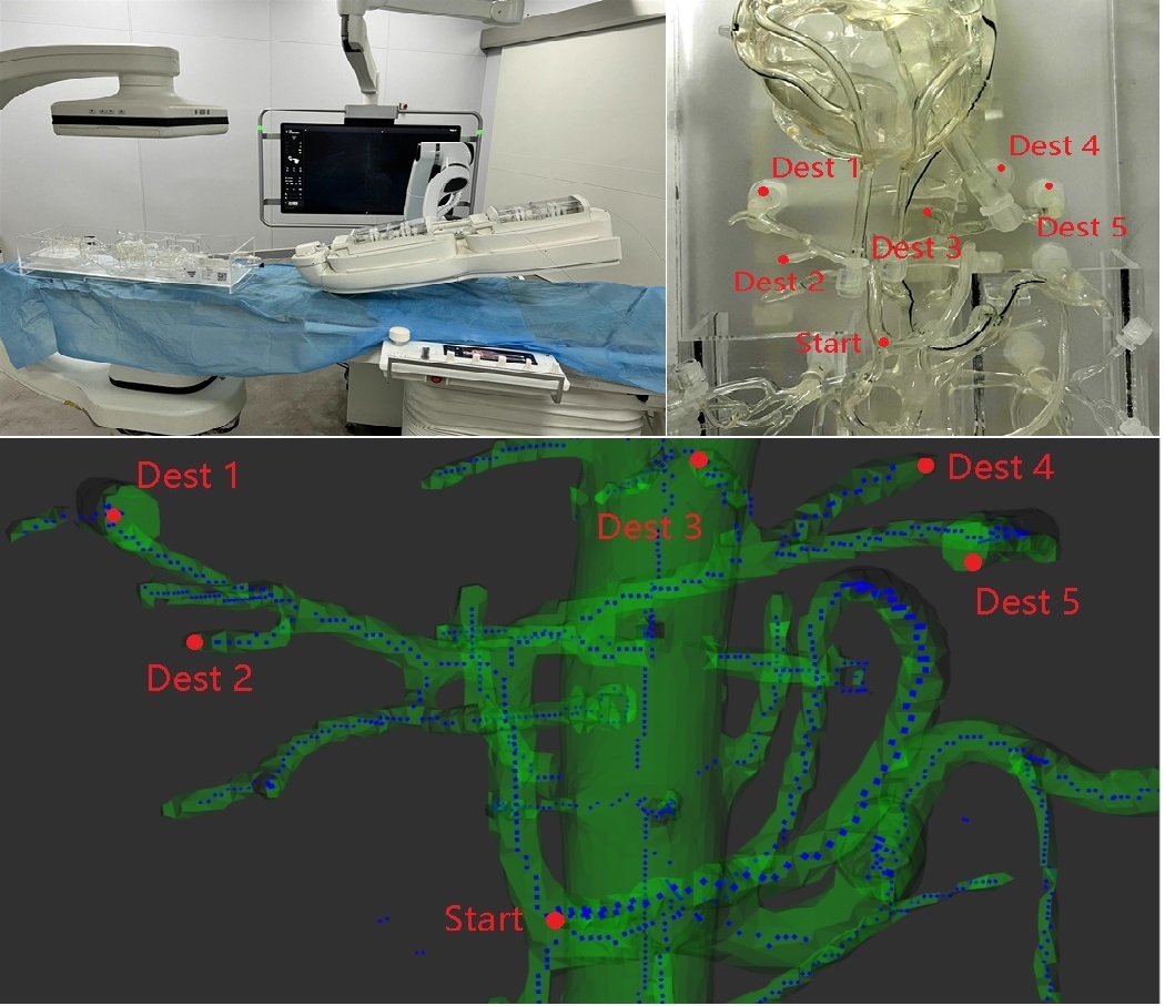
VascularPiolot3D was implemented as image receiver, 3D-2D registration, 2D endpoint extraction and navigation packages and mounted on Robot Operating System [32]. The complete software was deployed on a commercial laptop ALIENWARE M17 R4 (i7-10870H, 32Gb RAM, and GeForce RTX 3060 6Gb). 3D-2D registration package was implemented in C++ for efficient registration, and the rest were implemented in Python. Our own robot was built which carries VascularPiolot3D (see Fig. 3). The proposed VascularPiolot3D is modular to other widely used vascular robots as well. Pre-operative CT data of a 3D phantom was collected using United Imaging’s uCT 860 with volume size and voxel size . VascularPiolot3D grabbed real-time X-ray images from United Imaging’s uAngio 960. All collected 2D images were resized as . The average pixel size is in . The average delay from uAngio 960 to VascularPiolot3D is . The hyperparameters , , , and are set as , , , and .
fluroscopic X-ray images were collected and labeled to train the instrument segmentation network SA-UNet. Among them, were used for training, and for validation. VascularPilot3D was tested on a phantom that performs navigation on 5 different tasks shown in Fig. 3. 5 trials were conducted in each task and the average values and standard deviations were recorded. Since chosen tasks are typical tasks and VascularPiolot3D is prior-free, successful navigation can validate that VascularPiolot3D is suitable with any task without adaptation and training.

| Method | Task1 | Task2 | Task3 | Task4 | Task5 | |||||
| Mean | Std | Mean | Std | Mean | Std | Mean | Std | Mean | Std | |
| VascularPilot3D | 31.14 | 25.98 | 24.50 | 10.91 | 21.90 | 6.75 | 68.50 | 43.15 | 30.65 | 6.70 |
| Surgeon | 29.89 | 11.70 | 51.46 | 20.93 | 31.65 | 11.46 | 66.25 | 23.00 | 37.23 | 11.56 |
| RL navigation [2] | 53.67 | 31.04 | - | - | 40.67 | 21.04 | 57.00 | * | 26.33 | 8.11 |
III-A Navigation performances and time consumption
Fig. 4 shows selected sequential navigation results on both 2D and 3D end 111Readers are strongly advised to watch the attached video to appreciate the performance.. [2]’s RL approach was adopted since it is clear for our implementation. We followed [2]’s description and enhanced it by using the last 4 frames as state and pretraining with the expert’s operations. The rest setting strictly followed [2]’s description. A qualitative comparison was also conducted to compare the performance of VascularPilot3D and a professional surgeon. The surgeon obtained an M.D. Denote the one control loop as the cycle “imaging-localization-control-mechanic” (VascularPilot3D) and “imaging-control-mechanic” (human). This work compares the number of control loops in each navigation trial. It should be emphasized that time consumption cannot be fairly compared because of mechanical and imaging delay, and improvement in hardware will be our main focus in the future. VascularPilot3D achieves navigation success rate on five episodes of each task. Table I records the averages and standard deviations of trial control loops of in each task. It shows that VascularPilot3D outperforms the surgeon in 3 tasks out of 5. RL navigation [2] failed 5 out of 25 trials. Since [2]’s was implemented and trained by ourselves, and phantom was different, its result is for reference only. VascularPilot3D reduces surgeon’s overall control loops.
VascularPilot3D consumes totally and Otsu-based segmentation is the bottleneck. Time consumptions for vessel segmentation and 3D-2D alignment are around and . Global and local path plan consume less than and . Guidewire endpoint tracking costs per frame and runs in parallel.
III-B Limitations
VascularPiolot3D can be further improved by four directions. First, an additional force feedback control can determine the range of translation value for safety purposes and rapid parameter adaptation. Second, CPU-based Otsu-based segmentation (around ), mechanical (around ), and data transmission delay (around ) are most time-consuming. By polishing these modules, one-step control loop can be significantly improved from to less than . Thirdly, collaboration of guidewire and catheter is essential for real-world clinical applications. Lastly, VascularPiolot3D can be further improved for optimizing X-ray imaging direction to reduce radiation.
IV Conclusion
This work proposes the first 3D prior-free autonomous endovascular navigation system VascularPilot3D. VascularPilot3D is a complete system that infers the optimal sequential controls based on the pre-operative 3D and intra-operative continuous 2D fluoroscopy. Navigation in 3D space overcomes the ambiguous topological problem in existing 2D navigation works. VascularPilot3D has been coupled into our hardware system. Ex-vivo experiments on phantom validate that VascularPilot3D achieves success rate among 25 trials and reduce the surgeon’s overall control loops by .
References
- [1] G. Fagogenis, M. Mencattelli, Z. Machaidze, B. Rosa, K. Price, F. Wu, V. Weixler, M. Saeed, J. E. Mayer, and P. E. Dupont, “Autonomous robotic intracardiac catheter navigation using haptic vision,” Science robotics, vol. 4, no. 29, p. eaaw1977, 2019.
- [2] T. Behr, T. P. Pusch, M. Siegfarth, D. Hüsener, T. Mörschel, and L. Karstensen, “Deep reinforcement learning for the navigation of neurovascular catheters,” current directions in biomedical engineering, vol. 5, no. 1, pp. 5–8, 2019.
- [3] Y. Zhao, S. Guo, Y. Wang, J. Cui, Y. Ma, Y. Zeng, X. Liu, Y. Jiang, Y. Li, L. Shi, et al., “A CNN-based prototype method of unstructured surgical state perception and navigation for an endovascular surgery robot,” Medical & Biological Engineering & Computing, vol. 57, pp. 1875–1887, 2019.
- [4] W. Chi, G. Dagnino, T. M. Kwok, A. Nguyen, D. Kundrat, M. E. Abdelaziz, C. Riga, C. Bicknell, and G.-Z. Yang, “Collaborative robot-assisted endovascular catheterization with generative adversarial imitation learning,” in Proc. IEEE Int. Conf. Robot. and Automation, pp. 2414–2420, IEEE, 2020.
- [5] L. Karstensen, T. Behr, T. P. Pusch, F. Mathis-Ullrich, and J. Stallkamp, “Autonomous guidewire navigation in a two dimensional vascular phantom,” in Current Directions in Biomedical Engineering, vol. 6, p. 20200007, De Gruyter, 2020.
- [6] J. Kweon, K. Kim, C. Lee, H. Kwon, J. Park, K. Song, Y. I. Kim, J. Park, I. Back, J.-H. Roh, et al., “Deep reinforcement learning for guidewire navigation in coronary artery phantom,” IEEE Access, vol. 9, pp. 166409–166422, 2021.
- [7] L. Karstensen, J. Ritter, J. Hatzl, T. Pätz, J. Langejürgen, C. Uhl, and F. Mathis-Ullrich, “Learning-based autonomous vascular guidewire navigation without human demonstration in the venous system of a porcine liver,” Int. Jour. for Comp Assist. Rad. and Sur., vol. 17, no. 11, pp. 2033–2040, 2022.
- [8] P. Schegg, J. Dequidt, E. Coevoet, E. Leurent, R. Sabatier, P. Preux, and C. Duriez, “Automated planning for robotic guidewire navigation in the coronary arteries,” in 2022 IEEE 5th International Conference on Soft Robotics (RoboSoft), pp. 239–246, IEEE, 2022.
- [9] Ö. Çiçek, A. Abdulkadir, S. S. Lienkamp, T. Brox, and O. Ronneberger, “3D U-Net: learning dense volumetric segmentation from sparse annotation,” in Int. Conf. on Med. Image Comput. and Comput. Assist. Interv., pp. 424–432, Springer, 2016.
- [10] H. Yang, J. Chen, Y. Chi, X. Xie, and X. Hua, “Discriminative coronary artery tracking via 3D CNN in cardiac CT angiography,” in Int. Conf. on Med. Image Comput. and Comput. Assist. Interv., pp. 468–476, Springer, 2019.
- [11] Y.-C. Chen, Y.-C. Lin, C.-P. Wang, C.-Y. Lee, W.-J. Lee, T.-D. Wang, and C.-M. Chen, “Coronary artery segmentation in cardiac CT angiography using 3D multi-channel U-Net,” arXiv preprint arXiv:1907.12246, 2019.
- [12] Y. Lei, B. Guo, Y. Fu, T. Wang, T. Liu, W. Curran, L. Zhang, and X. Yang, “Automated coronary artery segmentation in coronary computed tomography angiography (CCTA) using deep learning neural networks,” in Medical Imaging 2020: Imaging Informatics for Healthcare, Research, and Applications, vol. 11318, pp. 279–284, SPIE, 2020.
- [13] L.-S. Pan, C.-W. Li, S.-F. Su, S.-Y. Tay, Q.-V. Tran, and W. P. Chan, “Coronary artery segmentation under class imbalance using a U-Net based architecture on computed tomography angiography images,” Scientific Reports, vol. 11, no. 1, p. 14493, 2021.
- [14] Y. Wu, S. Qi, M. Wang, S. Zhao, H. Pang, J. Xu, L. Bai, and H. Ren, “Transformer-based 3D U-Net for pulmonary vessel segmentation and artery-vein separation from ct images,” Medical & Biological Engineering & Computing, vol. 61, no. 10, pp. 2649–2663, 2023.
- [15] A. Zeng, C. Wu, G. Lin, W. Xie, J. Hong, M. Huang, J. Zhuang, S. Bi, D. Pan, N. Ullah, et al., “ImageCAS: A large-scale dataset and benchmark for coronary artery segmentation based on computed tomography angiography images,” Computerized Medical Imaging and Graphics, vol. 109, p. 102287, 2023.
- [16] N. Mu, Z. Lyu, M. Rezaeitaleshmahalleh, J. Tang, and J. Jiang, “An attention residual U-Net with differential preprocessing and geometric postprocessing: Learning how to segment vasculature including intracranial aneurysms,” Medical image analysis, vol. 84, p. 102697, 2023.
- [17] B. Kong, X. Wang, J. Bai, Y. Lu, F. Gao, K. Cao, J. Xia, Q. Song, and Y. Yin, “Learning tree-structured representation for 3D coronary artery segmentation,” Computerized Medical Imaging and Graphics, vol. 80, p. 101688, 2020.
- [18] G. Zhao, K. Liang, C. Pan, F. Zhang, X. Wu, X. Hu, and Y. Yu, “Graph convolution based cross-network multiscale feature fusion for deep vessel segmentation,” IEEE Trans. Med. Imag., vol. 42, no. 1, pp. 183–195, 2022.
- [19] Y. Li, Y. Zhang, W. Cui, B. Lei, X. Kuang, and T. Zhang, “Dual encoder-based dynamic-channel graph convolutional network with edge enhancement for retinal vessel segmentation,” IEEE Trans. Med. Imag., vol. 41, no. 8, pp. 1975–1989, 2022.
- [20] S. R. Aylward, J. Jomier, S. Weeks, and E. Bullitt, “Registration and analysis of vascular images,” Int. J. Comput. Vis., vol. 55, no. 2, pp. 123–138, 2003.
- [21] P. Markelj, D. Tomazevic, F. Pernus, and B. Likar, “Robust gradient-based 3-D/2-D registration of CT and MR to X-ray images,” IEEE Trans. Med. Imag., vol. 27, no. 12, pp. 1704–1714, 2008.
- [22] P. Steininger, M. Neuner, H. Weichenberger, G. Sharp, B. Winey, G. Kametriser, F. Sedlmayer, and H. Deutschmann, “Auto-masked 2D/3D image registration and its validation with clinical cone-beam computed tomography,” Physics in Medicine & Biology, vol. 57, no. 13, p. 4277, 2012.
- [23] D. Rivest-Henault, H. Sundar, and M. Cheriet, “Nonrigid 2D/3D registration of coronary artery models with live fluoroscopy for guidance of cardiac interventions,” IEEE Trans. Med. Imag., vol. 31, no. 8, pp. 1557–1572, 2012.
- [24] J. Song, K. Yang, Z. Zhang, M. Li, T. Cao, and M. Ghaffari, “Iterative PnP and its application in 3D-2D vascular image registration for robot navigation,” arXiv preprint arXiv:2310.12551, 2023.
- [25] N. Otsu, “A threshold selection method from gray-level histograms,” IEEE Trans. Syst., Man, Cybern., vol. 9, no. 1, pp. 62–66, 1979.
- [26] S. Moccia, E. De Momi, S. El Hadji, and L. S. Mattos, “Blood vessel segmentation algorithms—review of methods, datasets and evaluation metrics,” Computer methods and programs in biomedicine, vol. 158, pp. 71–91, 2018.
- [27] W. Clark, M. Ghaffari, and A. Bloch, “Nonparametric continuous sensor registration,” J. Mach. Learning Res., vol. 22, no. 1, pp. 12412–12461, 2021.
- [28] C. Guo, M. Szemenyei, Y. Yi, W. Wang, B. Chen, and C. Fan, “SA-UNet: Spatial attention U-Net for retinal vessel segmentation,” in Proc. Int. Conf. Pattern Recog., pp. 1236–1242, IEEE, 2021.
- [29] T. Y. Zhang and C. Y. Suen, “A fast parallel algorithm for thinning digital patterns,” Communications of the ACM, vol. 27, no. 3, pp. 236–239, 1984.
- [30] C. Duran, S. Estrada, M. O’Malley, A. B. Lumsden, and J. Bismuth, “Kinematics effectively delineate accomplished users of endovascular robotics with a physical training model,” Journal of Vascular Surgery, vol. 61, no. 2, pp. 535–541, 2015.
- [31] E. B. Mazomenos, P.-L. Chang, R. A. Rippel, A. Rolls, D. J. Hawkes, C. D. Bicknell, A. Desjardins, C. V. Riga, and D. Stoyanov, “Catheter manipulation analysis for objective performance and technical skills assessment in transcatheter aortic valve implantation,” Int. Jour. for Comp Assist. Rad. and Sur., vol. 11, pp. 1121–1131, 2016.
- [32] M. Quigley, K. Conley, B. Gerkey, J. Faust, T. Foote, J. Leibs, R. Wheeler, A. Y. Ng, et al., “ROS: an open-source Robot Operating System,” in ICRA workshop on open source software, vol. 3, p. 5, Kobe, Japan, 2009.