The comparative study of high efficiency of -doped fiber laser at for different pump schemes
Mohamed Zakia111E-mail: mohamed.zaki@edu.uiz.ac.ma, Mostafa ABOURICHAa222E-mail: m.abouricha@uiz.ac.ma and Said AMRANEb
aLPTHE, Department of Physics, Faculty of Sciences, Ibnou Zohr University, Agadir, Morocco.
bSTIC, Department of Physics, Faculty of Sciences, Chouaib Doukkali University, El Jadida, Morocco
Abstract
In this study, we revealed the impact of the pumping scheme, fiber length, pumping power, and reflectivity of the output fiber Bragg grating on the performance of a -doped fiber laser (TDFL) operating at a wavelength of . Using numerical simulations, we optimized the output power and reduced losses due to reabsorption; as well as amplified spontaneous emission (ASE) at approximately . The -doped fiber was bi-directionally pumped at to enhance the pump absorption. The simulations suggest that a maximum power of at and a slope efficiency of are achievable using a -doped silica fiber with a bi-directional pump of forward and backward.
Keywords: Thulium-doped fiber laser, Amplified spontaneous emission (ASE), , Pump scheme.
1 Introduction
Fiber laser sources emitting at wavelengths around , characterized by their high power, have attracted increasing interest due to their potential applications, notably in optical coherence tomography [1, 2, 3], laser surgery [4], remote sensing [5, 6], as well as for methane detection and in the processing of polymeric materials [7, 8, 9].
Many laser sources operating at the wavelength have recently been developed; utilizing nonlinear optical frequency conversion methods, including optical parametric oscillators and stimulated Raman scattering[10, 11, 12, 13]. However, significant advances have been made through the use of rare-earth-doped fibers, which offer a simpler and more robust solution for laser generation at this wavelength. For example, -doped fiber lasers (TDFL) operating at , which utilize energy level transitions within doped fibers, offer a wide emission range from to . These lasers can be efficiently pumped by erbium (Er) doped fiber lasers at or Er/Yb co-doped hybrid fibers [14]. Although the first TDFL at was introduced back in 2004 [15], these high-performance sources represent a recent innovation. This progress has paved the way for the direct use of these high-power fiber lasers, operating at , as pumping sources for dysprosium (Dy) doped fibers, enabling the generation of lasers in the mid-infrared range of to [16, 17, 18].
In recent years, much laser research has focused on improving the output power and efficiency of -doped fiber lasers at . These improvements include the use of fundamental transverse mode fiber laser pump sources from to , as well as careful design of the cavity layout [19, 20]. An interesting approach was proposed by Zhang et al., who developed an intra-cavity pumping scheme by placing a -doped fiber cavity inside a Er/Yb-doped fiber cavity. This configuration aims to improve pump absorption and minimize reabsorption loss [14]. In addition, Zhang et al. used a -doped silica fiber cavity, pumped from both ends by two Er/Yb-doped cavity fiber lasers [21].
In this study, we conducted a comprehensive investigation of the output characteristics of a continuous-wave (CW) thulium-doped fiber laser emitting at , which is powered by bidirectional pumping using two sources. The experimental setup, as demonstrated by Zhang et al.[21], was described; and a theoretical model based on the rate equations for the thulium-doped fiber was developed. The study then focused on the impact of the distribution of the pump power between the two ends of the fiber and the influence of the reflectivity of the output fiber Bragg grating (FBG2) on the output power, the laser threshold, and the optimal length of the active fiber. The analysis of the results is carried out through numerical simulations.
2 Theoretical model
2.1 Fiber Laser Schematic
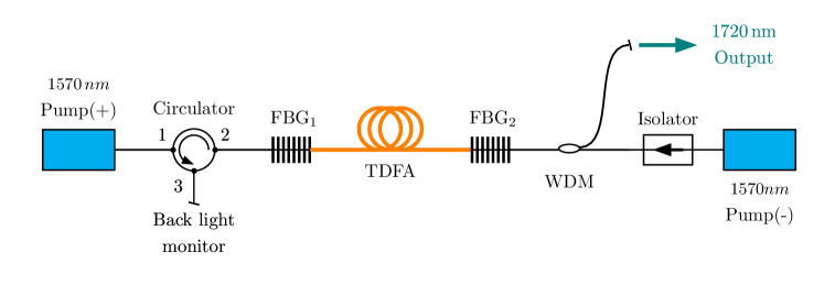
A schematic diagram of the laser is shown in Fig.1. The device consists of two Er/Yb-doped fiber lasers, designated as pump sources (pump(+) forward and pump(-) backward),to enhance the injected pumping power. Additionally, a segment of commercial fiber (Nufern SM-TSF-) was used as active fiber (TDF) with a low doping concentration is surrounded by two Fiber Bragg gratings, the first FBG1, located at the entrance to the laser cavity, has a reflectivity at and a bandwidth of , the second Fiber Bragg grating (FBG2), positioned at the cavity exit with a reflectivity at and a bandwidth of . The pump(-) source directs a laser into the cavity using an isolator and a wavelength multiplexer (WDM), which serves to separate the residual pump from the emitted laser. An optical circulator, functioning as an isolator, was installed between pump(+) and FBG1 to prevent the return of the residual pump laser. In addition, the free port (port 3) of the circulator is designed for managing the reverse ASE.
2.2 Rate equations
To find the numerical solutions of a -doped silica fiber amplifier subjected to pumping in a broadband transition that we have used here (see, for example [22, 23, 24]), a model and method are verified in different fiber laser regimes (-doped fiber [21], and Yb-doped fiber [25, 26]) and are based on the traditional rate equations that have been described in detail in this work ([27, 28]) and solved in the steady state considering the CW continuous-wave laser (i.e. time derivatives ). The pump power, signal and amplified spontaneous emission (ASE) propagation equations along the active fiber, which can be articulated as follows: [21, 29]
| (1) |
| (2) |
| (3) |
Where and represent the pump power, that of the signal laser and ASE signal at wavelength propagating along the z-axis forward and backward, respectively. In this model, the broadband ASE spectrum has been divided into channels with a wavelength interval of . is the wavelength of the channel, and is the ASE power at wavelength . is the pump overlap factor estimated as the ratio of the core area to the cladding area and the laser signal overlap factor in the -doped fiber, respectively ; and are the propagation loss coefficients at the pump wavelength and signal wavelength for the -doped fiber (including background loss and scattering loss), respectively; and are the emission and absorption cross sections taken [27, 30], respectively and in particular , , and are the pump and signal absorption and emission cross sections, respectively; and describe the population densities of ions in the ground state and the upper state in the longitudinal position of the fiber, respectively. and are linked by the following two relationships: [26, 31].
| (4) |
| (5) |
Where , is the total population density of ions, is the spontaneous emission lifetime and is the effective doping cross-section area with is the radius of the dope core. To simulate the evolution of the signal and pump power and the ASE, we used the fourth-order Runge-Kutta method, introducing the following pump and laser signal boundary conditions:
| (6) |
| (7) |
| (8) |
Where and are the pump powers launched into the front end (z = 0) by pump(+) source and the rear end (z = L) by pump(-) source , respectively; with L is the length of -doped fiber; and denote the reflectivity coefficient of the FBG1 and FBG2, respectively; is the FBG2 transmission coefficient such that ; indicates the insertion loss of the WDM at and the output optical isolator. The paraments of the -doped fiber are summarized in Tab.1.
| Quantity, Symbol | Value | Quantity, Symbol | Value |
|---|---|---|---|
| Pump wavelength, | 1570 nm | Thulium concentration, | |
| Signal wavelength, | 1720 nm | Core diameter, | |
| Pump overlap factor, | 0.70 | Clad diameter | 125 |
| Signal overlap factor, | 0.70 | Absorption cross section at , | |
| Propagation loss at , | Emission cross section at , | ||
| Propagation loss at , | Absorption cross section at , | ||
| Lifetime of the level, | 0.25 ms | Emission cross section at , | |
| The insertion loss, | 0.92 |
3 Discussion
3.1 The effect of pumping scheme
We first study the influence of pumping scheme on amplifier output power, setting the total input pump power at 10 W. The Fig.2 shows the evolution of output power as a function of fiber length for various pumping schemes (forward, backward, bidirectional). It can be seen that the bidirectional pumping scheme produces significantly higher output power at the optimum fiber length of 2.5 m.
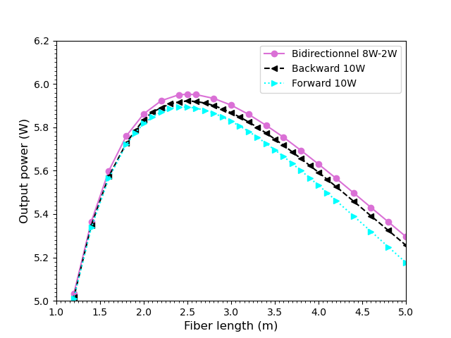
When the active fiber length exceeded the optimum value, the output power at began to drop rapidly with increasing active fiber length in all three pumping configurations, due to greater cavity loss induced by signal reabsorption.
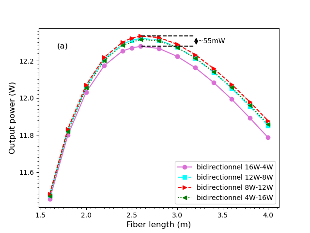
Next, we used the bidirectional pumping scheme, varying the percentage of total pumping power in both ends of the fiber to search for optimal values of pump source pumping power and pump source pumping power while keeping the total power value constant ( as shown in Fig.3a.
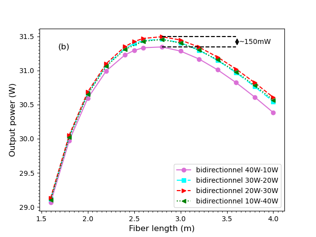
This analysis shows that when switching from the bidirectional to the bidirectional pumping scheme ( from pump source and from pump source), the maximum output power at length shows a minor increase of (). This increase becomes more significant close to ) when the pump power is equal to , as shown by Fig.4a and Fig.4b where pump powers of and are used, respectively.
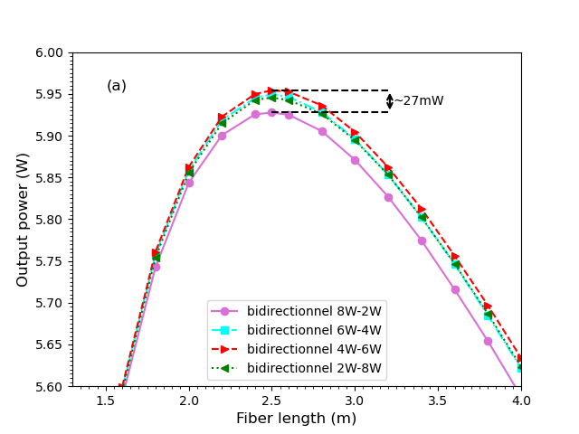
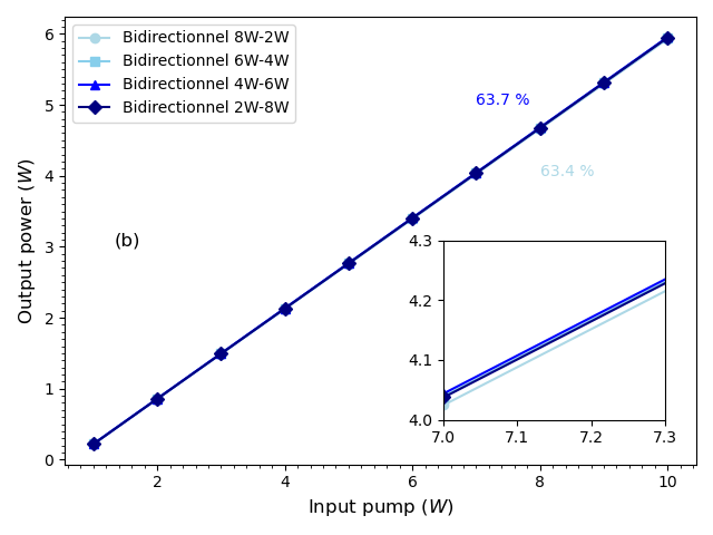
Fig.3b illustrates the relationship between the output power and the pump power for a -doped fiber. A variation in the threshold pump power is observed, shifting from in an bidirectional pumping configuration with an efficiency of , to in a bidirectional pumping configuration, which shows a slightly higher efficiency of . This means that the bidirectional pumping scheme compares favorably with other bidirectional pumping configurations, delivering considerably higher output power at the optimum fiber length.
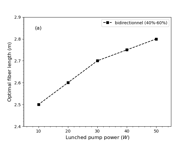
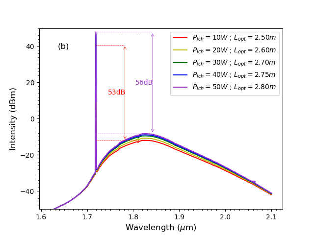
As the total pump power increases, the optimal length of the active fiber is not constant at and changes in a monotone fashion, as indicated by figures ( Fig.3a, Fig.4a, and Fig.4b, and more specifically Fig.5a). The increase in optimal length is caused by the low pump reabsorption and the rise in amplified spontaneous emission (ASE) around 1820 nm. When the fiber length exceeds this optimal point, both the output power and efficiency significantly decrease due to the inability to suppress the around . Furthermore, the improvement of the Signal-to-Noise Ratio (SNR) is modest when transitioning from a signal at with a pump power of to a signal with a pump power of , as indicated by as shown in Fig.5b.Consequently, selecting a pump power of 10W is deemed suitable to circumvent temperature-related effects.
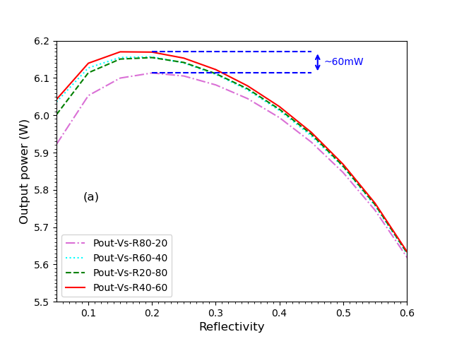
3.2 The effect of reflectivity
This section focuses on studying the influence of the reflectivity of the output Bragg grating (FBG2) on the output performance. According to the results illustrated in Fig.6a, it is noted that the output power at a wavelength of 1720 nm decreases with an increase in the reflectivity of the FBG. This trend is explained by a limitation in the power extraction rate within the laser cavity. In a bidirectional pumping configuration , the effect of reflectivity on output power is more pronounced, likely due to the increased intensity of the light reflected back towards the source.
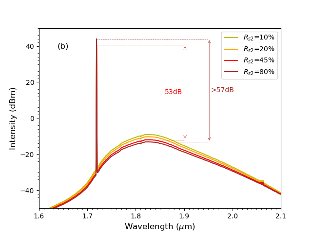
On the other hand, using an output FBG with low reflectivity reduces the intra-cavity signal power, which limits the ability to efficiently extract the gain from the -doped fiber. In this case, the spectral width of the spontaneous emission amplification (ASE) broadens, and its intensity at 1850 nm strengthens, directly influencing the performance of the laser at 1720 nm in terms of the signal-to-noise ratio (SNR) as demonstrated by Fig.6b. Consequently, to optimize the output power of the laser at 1720 nm, it would be preferable to choose an output FBG with a moderate reflectivity like , which has already been used in previous simulations
4 Conclusion
To conclude, this detailed numerical study examines the output characteristics of a thulium-doped silica fiber laser emitting at a wavelength of , based on a bidirectional pumping configuration. The analysis focused on the impact of several parameters, including pump power at , the length of the -doped fiber, and the reflectivity of the output fiber Bragg gratings (FBGs). The results reveal a maximum output power of , a slope efficiency of , and a reduced laser threshold to , achieved with a -doped fiber in a bidirectional pumping setup ( forward and reverse). We anticipate that these findings will contribute significantly to enhancing the performance of -doped fiber lasers, particularly around the wavelength.
References
- [1] Utkarsh Sharma, Ernest W Chang, and Seok H Yun. Long-wavelength optical coherence tomography at 1.7 m for enhanced imaging depth. Optics express, 16(24):19712–19723, 2008.
- [2] Masahito Yamanaka, Tatsuhiro Teranishi, Hiroyuki Kawagoe, and Norihiko Nishizawa. Optical coherence microscopy in 1700 nm spectral band for high-resolution label-free deep-tissue imaging. Scientific reports, 6(1):31715, 2016.
- [3] Shau Poh Chong, Conrad W Merkle, Dylan F Cooke, Tingwei Zhang, Harsha Radhakrishnan, Leah Krubitzer, and Vivek J Srinivasan. Noninvasive, in vivo imaging of subcortical mouse brain regions with 1.7 m optical coherence tomography. Optics letters, 40(21):4911–4914, 2015.
- [4] Min Wu, Krista Jansen, Antonius FW van der Steen, and Gijs van Soest. Specific imaging of atherosclerotic plaque lipids with two-wavelength intravascular photoacoustics. Biomedical optics express, 6(9):3276–3286, 2015.
- [5] Robert A Schowengerdt. Remote sensing: models and methods for image processing. elsevier, 2006.
- [6] Siamak Dawazdah Emami, Mahdi Mozdoor Dashtabi, Hui Jing Lee, Atoosa Sadat Arabanian, and Hairul Azhar Abdul Rashid. 1700 nm and 1800 nm band tunable thulium doped mode-locked fiber lasers. Scientific reports, 7(1):12747, 2017.
- [7] Ilya Mingareev, Fabian Weirauch, Alexander Olowinsky, Lawrence Shah, Pankaj Kadwani, and Martin Richardson. Welding of polymers using a 2 m thulium fiber laser. Optics & Laser Technology, 44(7):2095–2099, 2012.
- [8] Christophe Anselmo, Jean-Yves Welschinger, Jean-Pierre Cariou, Alain Miffre, and Patrick Rairoux. Gas concentration measurement by optical similitude absorption spectroscopy: methodology and experimental demonstration. Optics express, 24(12):12588–12599, 2016.
- [9] Paul Chambers, Ed AD Austin, and John P Dakin. Theoretical analysis of a methane gas detection system, using the complementary source modulation method of correlation spectroscopy. Measurement Science and Technology, 15(8):1629, 2004.
- [10] Jinyan Dong, Lei Zhang, Huawei Jiang, Xuezong Yang, Weiwei Pan, Shuzhen Cui, Xijia Gu, and Yan Feng. High order cascaded raman random fiber laser with high spectral purity. Optics Express, 26(5):5275–5280, 2018.
- [11] Rui Ma, Xin Quan, Ting Zhao, Dian Yuan Fan, and Jun Liu. Robust 1.69 m random fiber laser with high spectral purity based on ordinary fibers. Journal of Lightwave Technology, 40(12):3942–3946, 2022.
- [12] Yang Zhang, Jiaxin Song, Jun Ye, Jiangming Xu, Tianfu Yao, and Pu Zhou. Tunable random raman fiber laser at 1.7 m region with high spectral purity. Optics express, 27(20):28800–28807, 2019.
- [13] Wenxi Pei, Hao Li, Wei Huang, Meng Wang, and Zefeng Wang. Pulsed fiber laser oscillator at 1.7 m by stimulated raman scattering in h 2-filled hollow-core photonic crystal fibers. Optics Express, 29(21):33915–33925, 2021.
- [14] Lu Zhang, Junxiang Zhang, Quan Sheng, Yanyan Li, Chaodu Shi, Wei Shi, and Jianquan Yao. 1.7-m tm-doped fiber laser intracavity-pumped by an erbium/ytterbium-codoped fiber laser. Optics Express, 29(16):25280–25289, 2021.
- [15] Søren Agger, Jørn Hedegaard Povlsen, and Poul Varming. Single-frequency thulium-doped distributed-feedback fiber laser. Optics letters, 29(13):1503–1505, 2004.
- [16] Matthew R Majewski, Robert I Woodward, Jean-Yves Carreé, Samuel Poulain, Marcel Poulain, and Stuart D Jackson. Emission beyond 4 m and mid-infrared lasing in a dysprosium-doped indium fluoride (inf 3) fiber. Optics letters, 43(8):1926–1929, 2018.
- [17] Matthew R Majewski, Robert I Woodward, and Stuart D Jackson. Dysprosium mid-infrared lasers: current status and future prospects. Laser & Photonics Reviews, 14(3):1900195, 2020.
- [18] Z Tang, H Zhu, E Bereś-Pawlik, D Furniss, AB Seddon, TM Benson, S Sujecki, et al. Study of mid-infrared laser action in chalcogenide rare earth doped glass with dy 3+, pr 3+ and tb 3+. Optical Materials Express, 2(11):1632–1640, 2012.
- [19] Mark D Burns, Peter C Shardlow, Pranabesh Barua, Thomas L Jefferson-Brain, Jayanta K Sahu, and W Andrew Clarkson. 47 w continuous-wave 1726 nm thulium fiber laser core-pumped by an erbium fiber laser. Optics letters, 44(21):5230–5233, 2019.
- [20] JMO Daniel, N Simakov, M Tokurakawa, M Ibsen, and WA Clarkson. Ultra-short wavelength operation of a thulium fibre laser in the 1660–1750 nm wavelength band. Optics Express, 23(14):18269–18276, 2015.
- [21] Lu Zhang, Junxiang Zhang, Quan Sheng, Shijie Fu, Wei Shi, and Jianquan Yao. High-efficiency thulium-doped fiber laser at 1.7 m. Optics & Laser Technology, 152:108180, 2022.
- [22] MA Khamis and K Ennser. Enhancement on the generation of amplified spontaneous emission in thulium-doped silica fiber at 2 m. Optics communications, 403:127–132, 2017.
- [23] Clément Romano, Robert E Tench, and Jean-Marc Delavaux. Simulation of 2m single clad thulium-doped silica fiber amplifiers by characterization of the 3 f 4–3 h 6 transition. Optics Express, 26(20):26080–26092, 2018.
- [24] Stuart D Jackson. Towards high-power mid-infrared emission from a fibre laser. Nature photonics, 6(7):423–431, 2012.
- [25] Liang Shang. Comparative study of the output characteristics of ytterbium-doped double-clad fiber lasers with different pump schemes. Optik, 122(21):1899–1902, 2011.
- [26] Yankun Ren, Jianqiu Cao, Shaojun Du, and Jinbao Chen. Numerical study on the continuous-wave yb-doped fiber amplifiers operating near 980 nm. Optik, 161:118–128, 2018.
- [27] Pavel Peterka, Basile Faure, Wilfried Blanc, M Karasek, and Bernard Dussardier. Theoretical modelling of s-band thulium-doped silica fibre amplifiers. Optical and Quantum Electronics, 36:201–212, 2004.
- [28] Stuart D Jackson and Terence A King. Theoretical modeling of tm-doped silica fiber lasers. Journal of lightwave technology, 17(5):948, 1999.
- [29] Lu Zhang, Junxiang Zhang, Quan Sheng, Shuai Sun, Chaodu Shi, Shijie Fu, Xiaolei Bai, Qiang Fang, Wei Shi, and Jianquan Yao. Efficient multi-watt 1720 nm ring-cavity tm-doped fiber laser. Optics Express, 28(25):37910–37918, 2020.
- [30] Pavel Peterka, Ivan Kasik, Anirban Dhar, Bernard Dussardier, and Wilfried Blanc. Theoretical modeling of fiber laser at 810 nm based on thulium-doped silica fibers with enhanced 3 h 4 level lifetime. Optics express, 19(3):2773–2781, 2011.
- [31] Huihui Cheng, Wei Lin, Yu Zhang, Min Jiang, and Wei Luo. Numerical insights into the pulse instability in a ghz repetition-rate thulium-doped fiber laser. Journal of Lightwave Technology, 39(5):1464–1470, 2021.