Deep-learning design of graphene metasurfaces for quantum control and Dirac electron holography
Abstract
Metasurfaces are sub-wavelength patterned layers for controlling waves in physical systems. In optics, metasurfaces are created by materials with different dielectric constants and are capable of unconventional functionalities. We develop a deep-learning framework for Dirac-material metasurface design for controlling electronic waves. The metasurface is a configuration of circular graphene quantum dots, each created by an electric potential. Employing deep convolutional neural networks, we show that the original scattering wave can be reconstructed with fidelity over 95%, suggesting the feasibility of Dirac electron holography. Additional applications such as plane wave generation, designing broadband and multi-functionality graphene metasurface systems are illustrated.
I Introduction
Metasurfaces are two-dimensional (2D) arrays of subwavelength scatters. A common form of metasurfaces is metallic or dielectric structures for modulating or controlling electromagnetic waves to achieve desired wavefront, polarization distribution, intensity distribution or spectrum [1, 2, 3, 4, 5, 6]. Optical metasurfaces have wide applications such as planar lens and axicons [7, 8], vortex generators [9], beam deflectors [10], and holography [11, 12]. Compared with transform optics that requires continuous changes in the refractive index [13], metasurfaces contain distinct elements and are experimentally feasible. Metasurface design is important for problems such as surface plasmon polarization control, phase and amplitude reconstruction [14, 15], and metasurfaces have been exploited for acoustic [16, 17] and water surface wave [18, 19] devices as well. Metasurfaces can also be extended to matter waves. For example, in electron holography, information about the electron wave can be stored and reconstructed [20, 21], and the reconstructed wave can provide significantly improved resolution [22, 23].
An active area of research is to design metasurfaces according to specific goals [24]. A previous method was based on impedance retrieval that utilizes the local periodicity without optimization [25, 26], requiring large metasurfaces that overlap with the target region. A recent trend is to exploit machine learning [27, 28], where a rigorous solver of the metasurface scattering physics is approximated and replaced by a back-propagation type of neural network for high computational efficiency (e.g., thousand times faster than traditional optimization method) [29]. Another advantage of machine-learning design lies in its tolerance to constraints, in contrast to traditional optimization that relies on explicit but often unavailable constraints. For example, for designing devices with parameters in a fixed region by the interior-point method [29], generative adversarial neural networks [30] or physics-enhanced machine learning [31, 32] can be effective. For discrete target space, reinforcement learning can be used for optical metasurface design [33]. Quite recently, physics-informed neural networks for quantum control have been articulated [34].
In this paper, we address metasurface design for electronic waves in graphene, a widely studied 2D Dirac material [35, 36, 37, 38, 39, 40, 41, 42]. Under the continuum approximation, graphene is effectively a thin conducting layer [43, 44, 45], and a graphene metasurface can be used to manipulate electromagnetic waves [46, 47, 48], with gate potentials generating material layers of different refractive indices [49, 50, 51], thereby offering more flexibility than optical metasurfaces whose properties are fixed once designed. Experimentally, the required gate-potential profiles can be created by STM tip [52, 53, 54, 55] or doping [56]. For example, a periodic scattering structure leading to a graphene superlattice was realized [57, 58, 59, 60], with experimentally observed band structure [61]. A configuration of graphene scatters can generate complex scattering phenomena [62], and there were experiments on multiple graphene quantum dots formed by proper electric potential [63, 64].
We focus on designing graphene metasurface to control and manipulate Dirac electron scattering to generate any desired wavefront. Consider a point source emitting Dirac electronic waves with different energies through scattering from a graphene metasurface. For convenience, the region of observation, or the target region, is a rectangle whose side is approximately twice the wavelength. To be concrete, we assume that the metasurface consists of a small number of, e.g., six circular scatterers (quantum dots) of a fixed radius. In the language of Dirac electron optics, the design goal is to find the value of the dielectric constant of each quantum dot to generate any desired electronic waveform in the rectangular region of observation. This is an inverse-design problem of finding the optimal combination of the gate potentials applied to the quantum dots on the metasurface. Because of the need to test a large (infinite in principle) number of parameter combinations, optimization based on a rigorous Dirac equation solver is computationally infeasible. Moreover, estimating the derivatives of the solutions for optimization is challenging due to the need of calculating the inverse matrix at each time step. Our solution is to exploit deep convolutional neural networks (DCNNs) as a simulator for solving the Dirac equation [65, 66, 67]. We demonstrate that a designed metasurface of as few as six quantum dots can generate rich types of scattering wave. A phenomenon is that, given an actual scatterer with a complicated geometry, e.g., a star-like scatterer, a DCNN-designed metasurface can generate essentially the identical waveform in the target region, realizing Dirac electron holography. As will be demonstrated, given an optimization goal, it is even possible to generate broadband holography and multi-functional devices. Compared with optical metasurfaces whose physical parameters are fixed at the creation of the device, graphene based metasurfaces have the advantage of flexibility in that the physical parameters can be readily modified through the external gate potentials.
II Graphene metasurface and machine-learning design
II.1 Scattering physics from a graphene metasurface
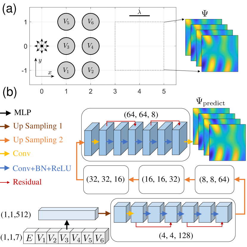
We consider a representative graphene metasurface system consisting of six circular scatterers, as shown in Figure. 1(a). In the single-electron framework, the Hamiltonian is
| (1) |
where is the Fermi velocity, is the vector of Pauli matrices, is the momentum of the electron, and is the potential energy profile that defines the th scatterer, for . For convenience, we use dimensionless units by setting . The six circles are identical and have the (dimensionless) radius , where the center of each circle is located in and and each potential-energy is created by a proper external gate potential. As a result, the geometric structure and the physical properties of a graphene metasurface are readily experimentally controllable, in contrast to optical metasurfaces defined by the material properties such as the dielectric constants that cannot be changed once chosen.
For electron holography in three dimensions (3D), energy conservation stipulates that the amplitude of a planar incidence wave decays inversely with the distance to the origin [68]. For a 2D graphene metasurface, the wave function can be written as a two-component spinor , where both components and are complex. The same energy consideration requires that the wave decays with the distance to the source as . A typical incident spinor wave can then be chosen as
| (2) |
where is the Hankel function of the first kind. We choose the post-scattering target region to be a square, as shown by dashed box defined as and in Fig. 1(a). For machine learning and loss-function computation, real quantities are required, so we introduce the following equivalent real spinor wave function: .
To solve the scattering problem, we use the multiple multipole (MMP) method originated from optics [69, 70, 71, 72, 73] and adopted to photonic crystal waveguides [74] and surface plasmons in metallic nanostructures [72]. The method has recently been extended to Dirac-Weyl spinor systems under different geometrical and mass settings [75, 76, 77, 78]. For a fixed set of gate potentials and incident energy, the resulting normalized scattering wave in the target region can be calculated using the MMP method, generating a forward solution.
Our inverse design addresses the problem of identifying an optimal combination of the electrical potentials applied to the scatterers to achieve a desired scattering wave, denoted as . To goal is to solve the following optimization problem:
| (3) |
where denotes the set of gate potentials and is a forward solution. Obtaining an optimal solution of requiring repeated use of the MMP method, one use for each potential configuration with variations determined by a gradient, which is computationally costly. Another difficulty lies in finding the gradient, which requires matrix inverse associated with the MMP method, which can be computationally extremely challenging. These difficulties motivated us to exploiting machine learning by using convolutional neural networks to approximate .
In optical metasurface design, two different types of problems often arise. One type concerns creating a metasurface to transfer energy, such as a planar lens [7, 8] or a beam deflector [10]. For this type of problems, the relevant physical quantity is the absolute light intensity or strength. The second type is holography [12], which requires reconstructing the phase and amplitude of the wave in some target region. For holography, the relative light strength is relevant since not all the input light energy can be used to construct a holographic object. In this case, the scattering wave inside the target region can be normalized to generate data of suitable scale for machine-learning design.
II.2 Deep convolutional neural networks
The basic idea of machine-learning design of graphene metasurface is to use a DCNN to substitute the Dirac equation solver (MMP). The input to the DCNN is the structure of the metasurface characterized by a vector of the gate potentials. The output of the DCNN is the spatial distribution of the spinor wave function. Since the wave functions spatially adjacent to each other are correlated as governed by the Dirac equation, DCNN trained to capture such correlations can be used to execute the same function as the Dirac equation. Such a neural network is equivalent to the inverse version of the neural networks typically used in image classification [79]. In particular, for image classification, a decrease in the spatial size is accompanied by a simultaneous increase in the channel size. For our inverse problem, increasing the spatial size then requires decreasing the channel size (to be explained below). In general, using the residual connection and batch normalization can improve the performance of deep neural networks and reduce overfitting [66, 80].
| Layer name | Kernel size | Padding | Stride |
| Up sampling 1 | |||
| Up sampling 2 | |||
| Conv |
Figure 1(b) shows the DCNN structure used in our study. The original input is a vector of seven components, one for energy and six for the the six gate potential profiles. Since the neural networks require a three-dimensional vector as the input, we add two dummy dimensions so the input is a three-dimensional matrix: , where the first two dimensions represent the space and the third value denotes the number of channels. After a multilayer Perceptron (MLP), the input matrix maps to a 3D matrix of dimension . Up sampling with convolutional kernel size , stride , and zero padding is performed next, where the number of channels is reduced in each upsampling with a simultaneous increase in the spacial dimension. The next is a convolutional block containing several convolutional layers , stride and padding. It also contains residual connections and batch normalization (BN) [80]. After the first block, another up sampling is performed with convolutional kernel size , stride , and padding, converning the 3D matrix into one of dimension . A similar structure is repeated three times. Finally, when the convolutional block of spacial dimension is done, we use a 2D convolutional layer and set the output dimension to be . Table 1 summarizes the three different convolutional layers used in our study. It is worth noting that, even with the same convolutional layer, the number of channels can be different for different blocks.
It is worth comparing our DCNN architecture with two typical neural networks for inverse design. First, compared with the traditional generative adversarial neural network (GAN) that was recently adopted for inverse design [30], our DCNN architecture contains a residual connection specifically for complicated training data, e.g., output wave function patterns from different energy values. Second, we note that the U-Net originally introduced for inverse design of medical images does not contain shortcut connections [65].
The training data are generated, as follows. We first set (quite arbitrarily) the energy range to be and choose the gate potential such that (these input data to the neural networks are normalized to the unit interval). As shown in Fig. 1(a), the size of the square target region to observe the scattering patterns of incident cylindrical waves is approximately two or three times of the incident wavelength. We then use the MMP method to calculate the scattering wave functions (see Appendix A for details). The target region is discretized into a grid and the wave function at each grid point is obtained. Finally, we normalize the wave function in the target region to generate the training data . Altogether, we generate training data sets (scattering patterns) from randomly generated energy and potential values in their respective ranges. For comparison, with brute-force sampling, since the input data is a seven-dimensional vector, training data sets are equivalent to taking only five points in each dimension.
| Description | Values |
| Batch size | |
| Learning rate | |
| Optimizer | Adam |
| Number of epochs | |
| Number of training data | 80,000 |
| Number of validating data | 10,000 |
| Number of testing data | 10,000 |
Table 2 lists the values of the training parameters. The loss function is the mean square error (MSE):
| (4) |
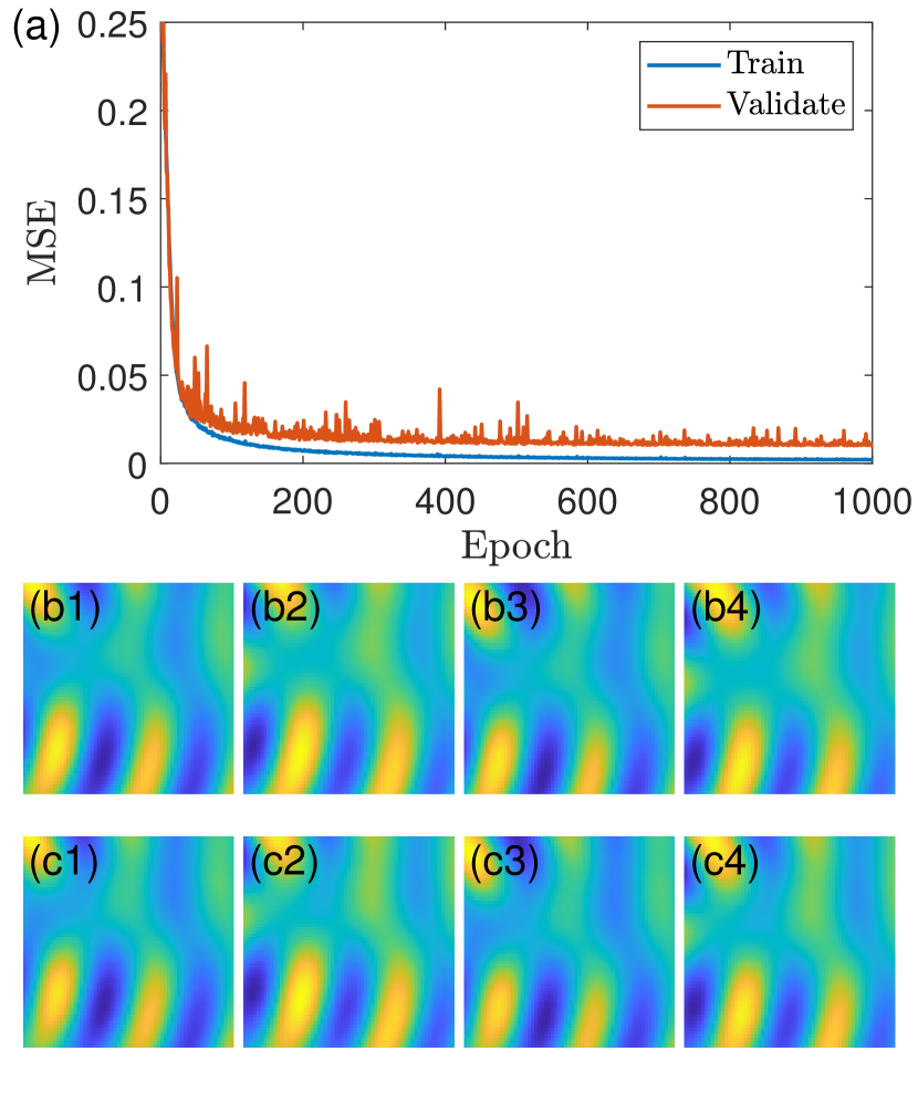
The neural network is built using PyTorch [81] and GPU is employed for fast training. Figure 2(a) shows the training and validating errors versus the epoch number. The fluctuations are mainly due to batch normalization used in the neural network, which can be reduced by using a larger batch size. However, a large batch slows down the convergence, so there is a computational tradeoff. Figures 2(b1-b4) and 2(c1-c4) show the true (calculated from the MMP method) and DCNN predicted scattering wave function from one example in the testing dataset whose MSE error is about the average testing error, where the four panels in each row correspond to the four real spinor components Re , Im , Re and Im , respectively. Visually, there is little difference between the DCNN predicted scattering patterns and the ground truth, indicating that effective training has been achieved. Table 3 lists the MSEs for training, evaluating and testing from the dataset with the smallest validation error. It can be seen that the training MSE is smaller than the validation and testing MSEs, indicating a certain degree of overfitting. Using more training data can help mitigating this problem.
| Description | Values |
| Training MSE | |
| Validating MSE | |
| Testing MSE |
III Dirac electron holography
A well-trained DCNN can substitute the real Dirac equation solver and provide an accurate solution in a computationally efficient way. In particular, with the available open source packages such as PyTorch [81], computing the loss and the gradient with respect to the input on GPU servers can be done extremely efficiently. For inverse design, the loss function is
| (5) |
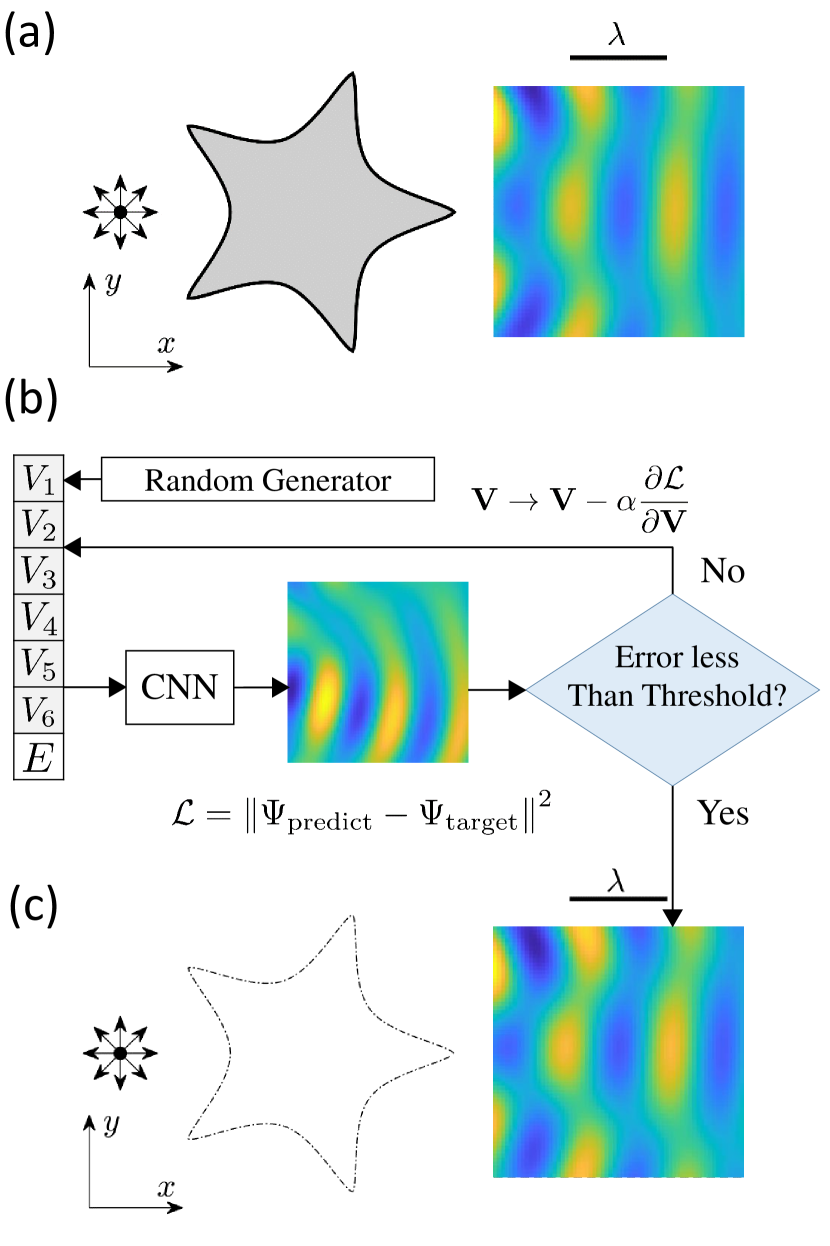
where is the output from the neural network and is the desired target wave. Figure 3 presents an example of generating a desired wave pattern, optimization, and creating Dirac electron holography. In particular, Fig. 3(a) shows a real scatterer of a star shape generated by the gate potential . For the cylindrical incident wave of energy , the scattering-wave pattern in the target region, calculated directly from this star scatterer using the MMP method (details in Appendix B), is also shown. Figure 3(b) shows the optimization algorithm to minimize the loss in Eq. (5), which starts from a randomly generated potential. We input the initial potential to the neural network and compute the loss and the gradient to variations in the metasurface parameter vector , and update by the optimization algorithm (source package scipy.optimize.minimize [82] in Python) at certain learning rate that depends on the specific optimization method. Note that, since the electron energy as an input to the neural network is given for the design process, we use the potentials to evaluate the gradient. In fact, with the known target wave pattern, the energy can be obtained from the Dirac equation. The optimization result depends on the initial condition, so we use a small ensemble of (ten) initial conditons and choose the potential configuration that yields the smallest value of . This combination of the potential values also gives the smallest loss in Eq. (3) for a properly trained DCNN. To demonstrate that the so-designed metasurface with the optimal potential configuration can generate the desired target wave pattern, we again employ the MMP method to calculate the scattering wave in the target region, but this time from the potential configuration. The resulting scattering wave pattern in shown in Fig. 3(c), which agrees well with that calculated from the star scatterer itself in Fig. 3(a). The DCNN generated metasurface can thus faithfully generate the desired scattering wave pattern from a geometrically complicated scatterer such as a star. Conversely, the metasurface generated wave pattern corresponds to the specific star scatterer, as shown by the dotted-dashed shape in Fig. 3(c), realizing Dirac electron holography!
To characterize the design accuracy, we define the following fidelity measure:
| (6) |
where is the normalized scattering wave generated by the metasurface and is the normalized wave from a target scatterer as governed by the Dirac equation, for the same energy . In the ideal case where the metasurface generates a wave that matches perfectly the target wave, we have (due to normalization).
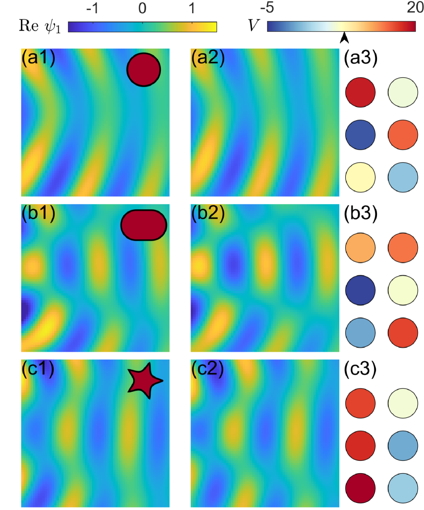
The general principle of holography is scattering wave matching, as can be seen by comparing the desired wave generated by a star-shaped scatterer in Fig. 3(a) and that generated by the designed metasurface in Fig. 3(c). Two more examples are shown in the upper and middle rows in Fig. 4, where the holographic objects have the shape of a circle and a stadium, respectively (the geometric parameters specified in Appendix B). The energy values for the two cases are . For comparison, we also include the case of the star-shaped holographic object (shown in Fig. 3) in the bottom row of Fig. 4. For the three cases, the desired wave pattens are shown in the left column, and those generated by the DCNN-designed metasurface are shown in the middle column, with the potential configuration of the metasurface in the right column. It can be seen that for the three holographic objects, an excellent scattering-wave matching has been achieved. The resulting fidelity values for three different energy values are listed in Tab. 4. In all cases, the fidelity values are larger than . Note that for a larger energy, the fidelity value decreases slightly due to the target region’s containing more wavelengths.
| Geometric shape | |||
| Circle | |||
| Stadium | |||
| Star |
There are some constraints for the loss function Eq. (5), which leads to a metasurface with specific phase matching. A constant phase shift will not only modify the spinors to , but also change the value of the loss function. While phase is important for interference-related problems in quantum system [83, 84], it is not crucial for physical quantities such as the local electron density, current and pseudospin polarization. For those phase-independent quantities, the loss function Eq. (5) may not yield the best structure. The second constraint is that the absolute information for the amplitude is missing in Eq. (5) due to normalization.
It is worth noting that, in optical holography, the energy corresponds to the input frequency and the potential configuration represents the dielectric property of the metasurface. If the output is a scattering cross section or transmission, MLPs are commonly used with the output being a vector covering all the frequencies [29]. For graphene metasurface, the aim of our inverse design is to achieve wave function matching, so the DCNN output is a matrix representing the scattering wave function. Another difference from optical metasurface is that the electron energy value is also input to the neural network, so the output is the wave function but at the specific energy value, enabling faster inverse design.
IV Other applications of machine-learning designed graphene metasurfaces
We address three additional applications of graphene metasurfaces.
IV.1 Plane wave generation
An important application of metasurfaces in optical system is to transform a cylindrical wave into another type of wave [25, 26]. To demonstrate that this is also possible with our machine-learning based Dirac electron holography, we begin with a spinor plane wave - a simple solution of the Dirac equation:
| (7) |
where and . We normalize the wave and set it as the desired wave pattern in the target region, and aim to transform an incident cylindrical wave into this plane wave. Note that, even without metasurface scattering, the cylindrical and plane waves share a certain degree of similarity, especially in the small energy regime, as indicated in the middle column of Tab. 5, where the values of “natural” (i.e., without any scatterer) fidelity between the two types of waves for several energies are listed. It can be seen that the fidelity value is high for small energy, and decreases as the energy increases. For a metasurface to be meaningful, for any energy the achieved fidelity value should be larger than the “natural” value.
| Energy | Fidelity (natural) | Fidelity (designed) |
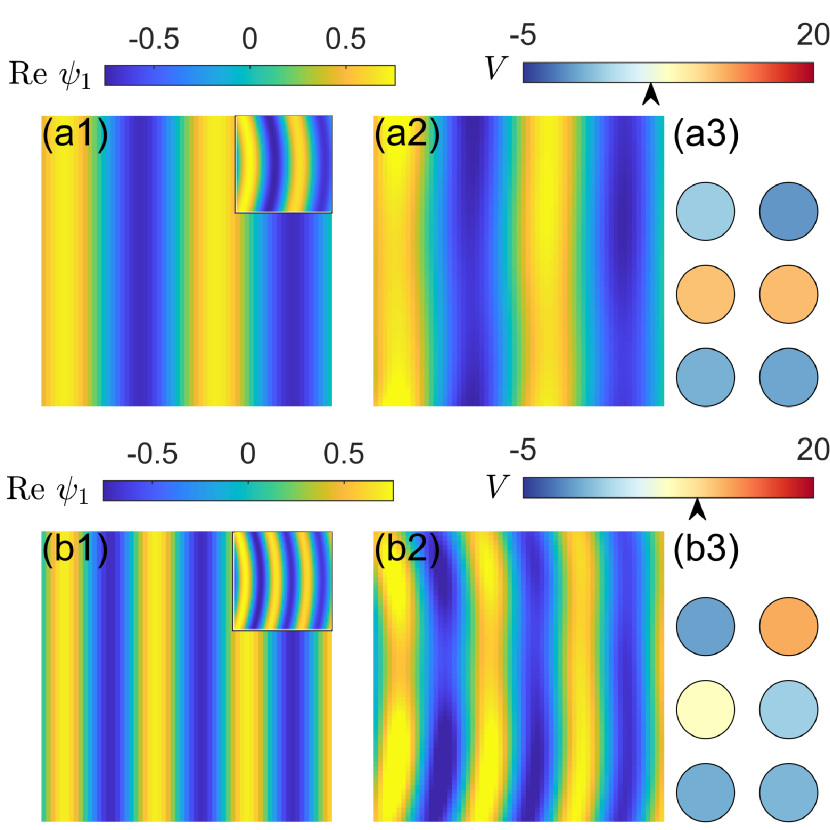
Figure 5(a1) shows the spatial pattern of taken from the plane wave for , where the upper-right inset is the incident wave. Figure 5(a2) shows the scattering wave from our DCNN-generated metasurface whose structure is displayed in Fig. 5(a3), where the color for each quantum dot indicates the potential value (red for high positive and blue for low negative value). The black arrow pointing at the upper color bar specifies the value of the incident energy. The fidelity achieved in this vase is . The striking similarity between the wave patterns in Figs. 5(a1) and 5(a2) is indicative of the success of the DCNN metasurface design. Another example is shown in Figs. 5(b1-b3), for a higher energy value: . The scattering wave pattern from the designed metasurface exhibits oscillations, due to the high energy. The third coloum of Tab. 5 lists the fidelity values from the metasurface generated plane waves for a number of energy values. As the energy increases, there is a slow decrease in the fidelity value. This can be explained by noting that, since the incident cylindrical wave is from the left, the scattering wave amplitude can take larger values on the left than on the right side of the metasurface scatterer, but an ideal plane wave has the same amplitude at any point in the propagation direction [the difference can be seen from Figs. 5(b1) and 5(b2)]. In addition, as the energy increases, the wavelength decreases so that the same target region of observation contains more wavelengths, making it more difficult for the designed metasurface to generate a plane wave in this region.
IV.2 Designing broadband graphene metasurface systems
For a metasurface system designed to modulate or control waves, whether optical or Dirac electron waves, bandwidth is an important characterizing quantity. In particular, will the system function as desired in a broad frequency (energy) range or will it work only for specific frequencies (energies)? The bandwidth issue is also crucial in other situations such as designing a wave system for cloaking or supperscattering in certain frequency (energy) range [85, 86, 67]. As illustrated in Fig. 3, the geometric shape of our DCNN-designed metasurface differs drastically from the actual scatterer. Since the potential configuration defining a specific metasurface was generated through scattering data at certain energies, acceptable wave matching (holography) cannot be anticipated to arise for all energies. Would it be possible to design a metasurface device with the desired functionality in a limited energy range? To address this question, we define the following quantity to characterize the bandwidth:
| (8) |
where and are the minimum and maximum wavelength and the performance of the metasurface system is acceptable for any wavelength . A similar quantity was introduced, e.g., in a previous work on designing a strong scattering system [29], where a suitable set of loss functions leading to strong scattering was effective even with about a shift in the wavelength. In another work [87], the geometrical phase was exploited to tolerate a wavelength shift in the inverse design.
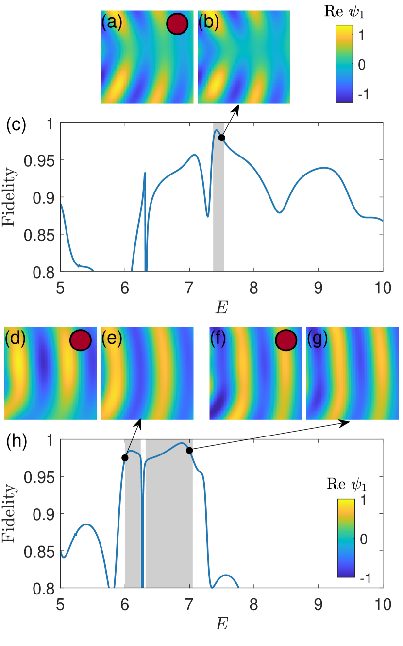
Our goal is to assess whether Dirac electron holography can be designed to function in a relatively broad energy range. To gain insights, we consider a circular graphene scatterer. Figure 6(a) shows the scattering wave pattern as a solution of the Dirac equation in the observational region for , where the scatterer is generated by the gate potential . Figure 6(b) shows the wave pattern from the corresponding metasurface at the same energy, which matches the actual pattern to a large extent. The question is, if the energy is changed, can a reasonable match between the two scattering wave patterns hold? To answer this question, we calculate the fidelity characterizing the wave-pattern matching for a wide energy range, as shown in Fig. 6(c), where the metasurface is designed for (indicated by the filled black circle) for which the fidelity value is . The vertical gray strip indicates the energy interval in which the fidelity is higher than . As the energy deviates from this interval, the fidelity value decreases rapidly, so the gray interval represents the bandwidth of the specific design, which is quite narrow relatively as it indicates that the design can tolerate only of the wavelength change.
We use the method of interval-training [29] to increase the bandwidth of the designed metasurface. The idea is to use the wave patterns in an energy interval for inverse design. The corresponding loss function is
| (9) |
If the energy interval is relatively narrow, the loss function can be approximated by
| (10) | ||||
To test the loss function in Eq. (10), we set and , and then minimize the loss to find the potential configuration . The true and metasurface-generated scattering wave patterns for the two energies are shown in Figs. 6(d-g), and Fig. 6(h) shows the fidelity versus the energy for , where the two black dots indicate the two energy values required by the loss function Eq. (10). For most energy values in the vertical gray shaded regions (except for a sharp drop about , the fidelity value is larger than , giving the wavelength bandwidth - a significant improvement compared with that from a single energy loss function, as shown in Fig. 6(c).
IV.3 Designing multi-functionality graphene metasurface
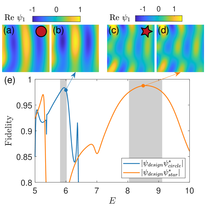
In optics, designing metasurfaces that can perform multiple functions was investigated [88]. For example, complicated metasurface can generate different holographic patterns at different frequencies [89]. Factors that can change the device properties include phase transition [90, 91] and biases [92, 93]. Here we address the problem of designing multi-functionality graphene metasurfaces through some proper gate potential configuration . To illustrate our approach, we consider two energy values and , where the desired scattering wave patterns for the two energy values are different. For example, for , the desired wave pattern should match that from a circular quantum dot, while for , the metasurface generated wave pattern should approxiate that from a star-shaped quantum dot, as shown in Figs. 7(a-d). The loss function is
| (11) | ||||
As a concrete example, we set and and perform optimization of the loss function to obtain the optimal potential configuration . Figure 7(e) shows the fidelity versus the energy , where the blue (orange) trace is the fidelity with respect to the scattering wave from the circular (star-shaped) quantum dot, with the respective shaded strips in which the fidelity value is larger than . The result suggests that two different functionalities can be realized by the designed graphene metasurface in two different energy intervals, respectively. Empirically, the two energy values should not be too close to each other. Also, assigning a higher energy value for more complicated scattering pattern (e.g., star-shaped dot) can be beneficial for the optimization process. An intuitive reason is that scattering patterns are generally more complicated at high energies, so using a complicated scatterer at a high energy value can provide more complexity to the neural network to enhance its computational capability and to generate a broad range of solutions of the Dirac equation.
V Discussion
Optical metasurfaces were invented to manipulate the wavefront and create holography. Naturally, the concept can be extended to other wave systems, such as the low-energy excitations in graphene governed by the Dirac equation. Existing studies of graphene metasurface focused mostly on its optical properties, i.e., its use as a dielectric medium to modulate electromagnetic waves. Whether graphene metasurfaces can be used to control electronic waves and to create Dirac electron holography remained to be an open question. In the present work, we addressed this question by developing a deep learning based, inverse-design framework to generate “electronic” graphene metasurfaces. The prototypical type of metasurface in our study consists of a small number of quantum dots on a graphene sheet, which can be realized through external electric gate voltages. Especially, the voltages applied to the quantum dots are different and constitute a set of parameters that can be optimized through machine learning. We demonstrated, using a graphene metasurface of six quantum dots, that various desired electronic wave patterns can be generated through quantum scattering and Dirac electron holography can be realized.
Our machine-learning design is to train a DCNN trained to generate a relation between a set of device parameters (e.g., the gate voltages) and a desired waveform that can be a plane wave or the scattering wave from a scatterer with a particular geometric shape. Training is done in an “offline” fashion to generate the required parameters for the metasurface. In the case of a single target wave, the wave generated by the metasurface can match the desired wave with fidelity higher than . Such a high-fidelity wave matching is essentially what is required for producing Dirac electron holograph. For metasurfaces generated from training data from a single energy value, waveform matching can be achived in a small interval about this energy value. To increase the energy (frequency) band, we articulated a loss function that involves the desired and deep-learning predicted wave functions at multiple energy values. Dual functionalities were also demonstrated where a metasurface system can realize Dirac electron holography at two distinct energy values.
One requirement in our framework is that the designed metasurface functions for the same energy values used to generate the waveforms for training. In machine learning, this is referred to as the problem of “overlapping of the design space with the training space.” This is in fact a common difficulty for inverse design of wave scattering systems. Another challenge is that, during the training process, the DCNN are updated iteratively, which requires a large computational load. Use of generative adversarial neural networks [30] can reduce the computations, as it directly finds a relation between the desired performance and the device parameters. A difficulty is that the devices parameters so produced can often be unphysical, requiring some sophisticated filtering process to obtain physical reasonable parameter values.
The capacity achieved in this paper for controlling Dirac electron waves through graphene metasurfaces is relatively small compared to what metasurfaces can do to optical waves, for two reasons. First, scattering occurs in 2D so the wave amplitude on the side of the target observational region closer to the source is larger than that on the opposite side. Second, electron scattering in Dirac systems is generally weak due to Klein tunneling. These two factors limite the type of waveforms that can be generated by a graphene metasurface. Nonetheless, to our knowledge, prior to our work, Dirac electron holography had not been reported. Our work provides an initial step in manipulating or controlling Dirac waves with the aid of modern machine learning.
Appendix A Generating data using multiple multipole method
Our training data are the scattering waveforms from a sophisticated scatterer such as a star-shaped quantum dot, which are generated by the MMP method originated in optics [69, 70, 71, 72, 73, 74] and adopted to Dirac-Weyl spinor systems [75, 76, 77, 78]. After a graphene metasurface has been designed, testing it also requires solving the scattering field from it, which is also done using the MMP method. Take the metasurface of six quantum dots as an example. The basic idea of MMP is to place poles both inside and outside of each boundary, as shown in Fig. 8(a). The wave function outside the metasurface is determined by all the poles inside the circular boundaries, and the corresponding poles outside each circular boundary determine the wave function inside the circle. The detailed computational procedure can be be found in Ref. [78].
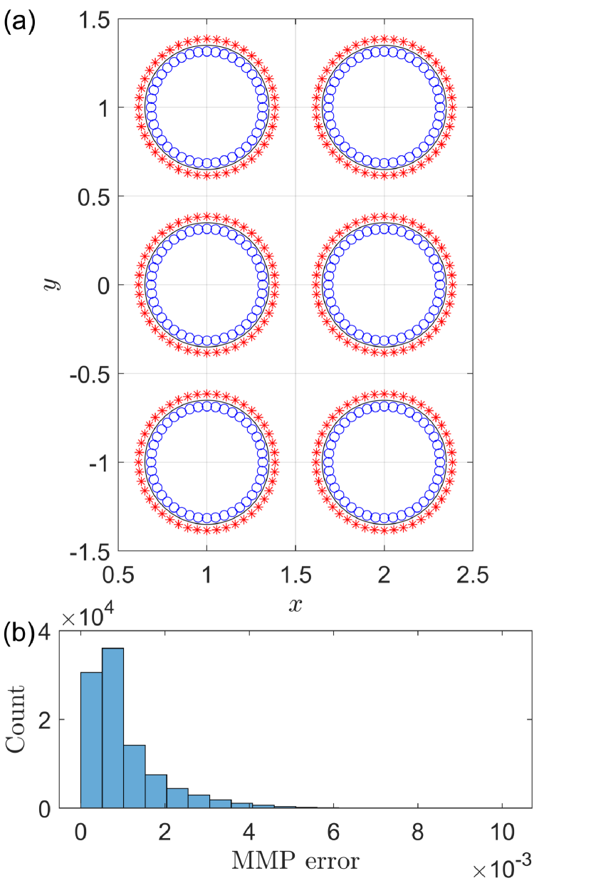
In our calculation, poles inside each circle are located at at the same angular interval. The number of poles inside each circle is . Poles outside the circle are located at and their number is . The boundary is discretized with points. Each pole generates three values of the angular momentum: . For a given metasurface, calculating the scattering waveform requires solving roughly equations with approximately unknown parameters. Figure 8(b) shows a typical histogram of the MMP boundary fitting errors [75], which are sufficiently small to guarantee accurate wave solutions. Altogether, about waveforms are produced for the results reported in this paper.
Appendix B Generating target scattering wave
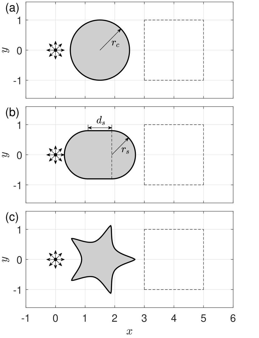
The desired target waveforms are calculated using the MMP method for the geometrical structures shown in Figs. 9(a-c). The circle in Fig. 9(a) has the radius and is centered at at . The two geometric parameters defining the stadium scatterer in Fig. 9(b) are and the center is located at . The shape of star scatterer is determined by the Gielis formula [94]:
| (12) |
with the parameters , , , , , and . The center of the star is located at .
Data and code availability
Data and codes are available from GitHub: https://github.com/hanchendi/Dirac-Electron-Holography
Acknowledgments
This work was supported by the Air Force Office of Scientific Research (AFOSR) under Grant No. FA9550-21-1-0438. VK was supported in part by IDQ (a Quantum Communications Company) and by NSF under Grant No. NSF-2328991.
Author Contributions
All designed the research project, the models, and methods. C.-D.H. performed the computations. All analyzed the data. C.-D.H. and Y.-C.L. wrote the paper.
Competing Interests
The authors declare no competing interests.
Correspondence
To whom correspondence should be addressed: Ying-Cheng.Lai@asu.edu
References
- Kildishev, Boltasseva, and Shalaev [2013] A. V. Kildishev, A. Boltasseva, and V. M. Shalaev, “Planar photonics with metasurfaces,” Science 339, 1232009 (2013).
- Yu and Capasso [2014] N. Yu and F. Capasso, “Flat optics with designer metasurfaces,” Nat. Mater. 13, 139–150 (2014).
- Chen, Taylor, and Yu [2016] H.-T. Chen, A. J. Taylor, and N. Yu, “A review of metasurfaces: physics and applications,” Rep. Prog. Phys. 79, 076401 (2016).
- Lalanne and Chavel [2017] P. Lalanne and P. Chavel, “Metalenses at visible wavelengths: past, present, perspectives,” Laser Photonics Rev. 11, 1600295 (2017).
- Kamali et al. [2018] S. M. Kamali, E. Arbabi, A. Arbabi, and A. Faraon, “A review of dielectric optical metasurfaces for wavefront control,” Nanophotonics 7, 1041–1068 (2018).
- Shaltout, Shalaev, and Brongersma [2019] A. M. Shaltout, V. M. Shalaev, and M. L. Brongersma, “Spatiotemporal light control with active metasurfaces,” Science 364, eaat3100 (2019).
- Aieta et al. [2012] F. Aieta, P. Genevet, M. A. Kats, N. Yu, R. Blanchard, Z. Gaburro, and F. Capasso, “Aberration-free ultrathin flat lenses and axicons at telecom wavelengths based on plasmonic metasurfaces,” Nano Lett. 12, 4932–4936 (2012).
- Ni et al. [2013] X. Ni, S. Ishii, A. V. Kildishev, and V. M. Shalaev, “Ultra-thin, planar, babinet-inverted plasmonic metalenses,” Light Sci. Appl. 2, e72–e72 (2013).
- Genevet et al. [2012] P. Genevet, N. Yu, F. Aieta, J. Lin, M. A. Kats, R. Blanchard, M. O. Scully, Z. Gaburro, and F. Capasso, “Ultra-thin plasmonic optical vortex plate based on phase discontinuities,” Appl. Phys. Lett. 100, 013101 (2012).
- Shalaev et al. [2015] M. I. Shalaev, J. Sun, A. Tsukernik, A. Pandey, K. Nikolskiy, and N. M. Litchinitser, “High-efficiency all-dielectric metasurfaces for ultracompact beam manipulation in transmission mode,” Nano Lett. 15, 6261–6266 (2015).
- Ni, Kildishev, and Shalaev [2013] X. Ni, A. V. Kildishev, and V. M. Shalaev, “Metasurface holograms for visible light,” Nat. Commun. 4, 1–6 (2013).
- Huang, Zhang, and Zentgraf [2018] L. Huang, S. Zhang, and T. Zentgraf, “Metasurface holography: from fundamentals to applications,” Nanophotonics 7, 1169–1190 (2018).
- Pendry, Schurig, and Smith [2006] J. B. Pendry, D. Schurig, and D. R. Smith, “Controlling electromagnetic fields,” Science 312, 1780–1782 (2006).
- Dolev, Epstein, and Arie [2012] I. Dolev, I. Epstein, and A. Arie, “Surface-plasmon holographic beam shaping,” Phys. Rev. Lett. 109, 203903 (2012).
- Xu et al. [2017] Q. Xu, X. Zhang, Y. Xu, C. Ouyang, Z. Tian, J. Gu, J. Li, S. Zhang, J. Han, and W. Zhang, “Polarization-controlled surface plasmon holography,” Laser Photonics Rev. 11, 1600212 (2017).
- Yang et al. [2016] Y. Yang, H. Wang, F. Yu, Z. Xu, and H. Chen, “A metasurface carpet cloak for electromagnetic, acoustic and water waves,” Sci. Rep. 6, 1–6 (2016).
- Assouar et al. [2018] B. Assouar, B. Liang, Y. Wu, Y. Li, J.-C. Cheng, and Y. Jing, “Acoustic metasurfaces,” Nat. Rev. Mater. 3, 460–472 (2018).
- Sun et al. [2016] H. Sun, J. Wang, Y. Cheng, Q. Wei, and X. Liu, “Modulation of water surface waves with a coiling-up-space metasurface,” AIP Adv. 6, 055017 (2016).
- Zou et al. [2019] S. Zou, Y. Xu, R. Zatianina, C. Li, X. Liang, L. Zhu, Y. Zhang, G. Liu, Q. H. Liu, H. Chen, et al., “Broadband waveguide cloak for water waves,” Phys. Rev. Lett. 123, 074501 (2019).
- Tonomura [1987] A. Tonomura, “Applications of electron holography,” Rev. Mod. Phys. 59, 639 (1987).
- Lichte and Lehmann [2007] H. Lichte and M. Lehmann, “Electron holography—basics and applications,” Rep. Prog. Phys. 71, 016102 (2007).
- Tonomura, Matsuda, and Endo [1979] A. Tonomura, T. Matsuda, and J. Endo, “High resolution electron holography with field emission electron microscope,” Jpn. J. Appl. Phys. 18, 9 (1979).
- Orchowski, Rau, and Lichte [1995] A. Orchowski, W. Rau, and H. Lichte, “Electron holography surmounts resolution limit of electron microscopy,” Phys. Rev. Lett. 74, 399 (1995).
- Elsawy et al. [2020] M. M. Elsawy, S. Lanteri, R. Duvigneau, J. A. Fan, and P. Genevet, “Numerical optimization methods for metasurfaces,” Laser Photonics Rev. 14, 1900445 (2020).
- Wan et al. [2014] X. Wan, Y. B. Li, B. G. Cai, and T. J. Cui, “Simultaneous controls of surface waves and propagating waves by metasurfaces,” Appl. Phys. Lett. 105, 121603 (2014).
- Martini, Mencagli Jr, and Maci [2015] E. Martini, M. Mencagli Jr, and S. Maci, “Metasurface transformation for surface wave control,” Philos. Trans. R. Soc. London A 373, 20140355 (2015).
- So et al. [2020] S. So, T. Badloe, J. Noh, J. Bravo-Abad, and J. Rho, “Deep learning enabled inverse design in nanophotonics,” Nanophotonics 9, 1041–1057 (2020).
- Wiecha et al. [2021] P. R. Wiecha, A. Arbouet, C. Girard, and O. L. Muskens, “Deep learning in nano-photonics: inverse design and beyond,” Photon. Res. 9, B182–B200 (2021).
- Peurifoy et al. [2018] J. Peurifoy, Y. Shen, L. Jing, Y. Yang, F. Cano-Renteria, B. G. DeLacy, J. D. Joannopoulos, M. Tegmark, and M. Soljačić, “Nanophotonic particle simulation and inverse design using artificial neural networks,” Sci. Adv. 4, eaar4206 (2018).
- Liu et al. [2018] Z. Liu, D. Zhu, S. P. Rodrigues, K.-T. Lee, and W. Cai, “Generative model for the inverse design of metasurfaces,” Nano Lett. 18, 6570–6576 (2018).
- Jiang and Fan [2019] J. Jiang and J. A. Fan, “Global optimization of dielectric metasurfaces using a physics-driven neural network,” Nano Lett. 19, 5366–5372 (2019).
- Chen et al. [2022] M. Chen, R. Lupoiu, C. Mao, D.-H. Huang, J. Jiang, P. Lalanne, and J. A. Fan, “High speed simulation and freeform optimization of nanophotonic devices with physics-augmented deep learning,” ACS Photonics 9, 3110–3123 (2022).
- Sajedian, Badloe, and Rho [2019] I. Sajedian, T. Badloe, and J. Rho, “Optimisation of colour generation from dielectric nanostructures using reinforcement learning,” Opt. Exp. 27, 5874–5883 (2019).
- Norambuena et al. [2024] A. Norambuena, M. Mattheakis, F. J. González, and R. Coto, “Physics-informed neural networks for quantum control,” Phys. Rev. Lett. 132, 010801 (2024).
- Novoselov et al. [2004] K. S. Novoselov, A. K. Geim, S. V. Morozov, D.-e. Jiang, Y. Zhang, S. V. Dubonos, I. V. Grigorieva, and A. A. Firsov, “Electric field effect in atomically thin carbon films,” Science 306, 666–669 (2004).
- Novoselov et al. [2005] K. S. Novoselov, A. K. Geim, S. V. Morozov, D. Jiang, M. I. Katsnelson, I. Grigorieva, S. Dubonos, and a. Firsov, “Two-dimensional gas of massless dirac fermions in graphene,” Nature 438, 197–200 (2005).
- Gusynin and Sharapov [2005] V. Gusynin and S. Sharapov, “Unconventional integer quantum hall effect in graphene,” Phys. Rev. Lett. 95, 146801 (2005).
- Rycerz, Tworzydło, and Beenakker [2007] A. Rycerz, J. Tworzydło, and C. Beenakker, “Valley filter and valley valve in graphene,” Nat. Phys. 3, 172–175 (2007).
- Han et al. [2014] W. Han, R. K. Kawakami, M. Gmitra, and J. Fabian, “Graphene spintronics,” Nat. Nanotechnol. 9, 794–807 (2014).
- Cao et al. [2018a] Y. Cao, V. Fatemi, S. Fang, K. Watanabe, T. Taniguchi, E. Kaxiras, and P. Jarillo-Herrero, “Unconventional superconductivity in magic-angle graphene superlattices,” Nature 556, 43–50 (2018a).
- Cao et al. [2018b] Y. Cao, V. Fatemi, A. Demir, S. Fang, S. L. Tomarken, J. Y. Luo, J. D. Sanchez-Yamagishi, K. Watanabe, T. Taniguchi, E. Kaxiras, et al., “Correlated insulator behaviour at half-filling in magic-angle graphene superlattices,” Nature 556, 80–84 (2018b).
- Neto et al. [2009] A. C. Neto, F. Guinea, N. M. Peres, K. S. Novoselov, and A. K. Geim, “The electronic properties of graphene,” Rev. Mod. Phys. 81, 109 (2009).
- Gusynin, Sharapov, and Carbotte [2006] V. Gusynin, S. Sharapov, and J. Carbotte, “Unusual microwave response of dirac quasiparticles in graphene,” Phys. Rev. Lett. 96, 256802 (2006).
- Mikhailov and Ziegler [2007] S. A. Mikhailov and K. Ziegler, “New electromagnetic mode in graphene,” Phys. Rev. Lett. 99, 016803 (2007).
- Falkovsky [2008] L. A. Falkovsky, “Optical properties of graphene,” J. Phys. Conf. Ser. 129, 012004 (2008).
- Fallahi and Perruisseau-Carrier [2012] A. Fallahi and J. Perruisseau-Carrier, “Design of tunable biperiodic graphene metasurfaces,” Phys. Rev. B 86, 195408 (2012).
- Miao et al. [2015] Z. Miao, Q. Wu, X. Li, Q. He, K. Ding, Z. An, Y. Zhang, and L. Zhou, “Widely tunable terahertz phase modulation with gate-controlled graphene metasurfaces,” Phys. Rev. X 5, 041027 (2015).
- Guo and Argyropoulos [2016] T. Guo and C. Argyropoulos, “Broadband polarizers based on graphene metasurfaces,” Opt. Lett. 41, 5592–5595 (2016).
- Allain and Fuchs [2011] P. E. Allain and J.-N. Fuchs, “Klein tunneling in graphene: optics with massless electrons,” Eur. Phys. J. B 83, 301–317 (2011).
- Ozawa et al. [2017] T. Ozawa, A. Amo, J. Bloch, and I. Carusotto, “Klein tunneling in driven-dissipative photonic graphene,” Phys. Rev. A 96, 013813 (2017).
- Han et al. [2018] C.-D. Han, C.-Z. Wang, H.-Y. Xu, D. Huang, and Y.-C. Lai, “Decay of semiclassical massless dirac fermions from integrable and chaotic cavities,” Phys. Rev. B 98, 104308 (2018).
- Zhao et al. [2015] Y. Zhao, J. Wyrick, F. D. Natterer, J. F. Rodriguez-Nieva, C. Lewandowski, K. Watanabe, T. Taniguchi, L. S. Levitov, N. B. Zhitenev, and J. A. Stroscio, “Creating and probing electron whispering-gallery modes in graphene,” Science 348, 672–675 (2015).
- Lee et al. [2016] J. Lee, D. Wong, J. Velasco Jr, J. F. Rodriguez-Nieva, S. Kahn, H.-Z. Tsai, T. Taniguchi, K. Watanabe, A. Zettl, F. Wang, et al., “Imaging electrostatically confined dirac fermions in graphene quantum dots,” Nat. Phys. 12, 1032–1036 (2016).
- Gutiérrez et al. [2016] C. Gutiérrez, L. Brown, C.-J. Kim, J. Park, and A. N. Pasupathy, “Klein tunnelling and electron trapping in nanometre-scale graphene quantum dots,” Nat. Phys. 12, 1069–1075 (2016).
- Ghahari et al. [2017] F. Ghahari, D. Walkup, C. Gutiérrez, J. F. Rodriguez-Nieva, Y. Zhao, J. Wyrick, F. D. Natterer, W. G. Cullen, K. Watanabe, T. Taniguchi, et al., “An on/off berry phase switch in circular graphene resonators,” Science 356, 845–849 (2017).
- Velasco Jr et al. [2016] J. Velasco Jr, L. Ju, D. Wong, S. Kahn, J. Lee, H.-Z. Tsai, C. Germany, S. Wickenburg, J. Lu, T. Taniguchi, et al., “Nanoscale control of rewriteable doping patterns in pristine graphene/boron nitride heterostructures,” Nano Lett. 16, 1620–1625 (2016).
- Bai and Zhang [2007] C. Bai and X. Zhang, “Klein paradox and resonant tunneling in a graphene superlattice,” Phys. Rev. B 76, 075430 (2007).
- Tiwari and Stroud [2009] R. P. Tiwari and D. Stroud, “Tunable band gap in graphene with a noncentrosymmetric superlattice potential,” Phys. Rev. B 79, 205435 (2009).
- Burset et al. [2011] P. Burset, A. L. Yeyati, L. Brey, and H. Fertig, “Transport in superlattices on single-layer graphene,” Phys. Rev. B 83, 195434 (2011).
- Killi, Wu, and Paramekanti [2011] M. Killi, S. Wu, and A. Paramekanti, “Band structures of bilayer graphene superlattices,” Phys. Rev. Lett. 107, 086801 (2011).
- Ponomarenko et al. [2013] L. Ponomarenko, R. Gorbachev, G. Yu, D. Elias, R. Jalil, A. Patel, A. Mishchenko, A. Mayorov, C. Woods, J. Wallbank, et al., “Cloning of dirac fermions in graphene superlattices,” Nature 497, 594–597 (2013).
- Sadrara and Miri [2019] M. Sadrara and M. Miri, “Dirac electron scattering from a cluster of electrostatically defined quantum dots in graphene,” Phys. Rev. B 99, 155432 (2019).
- Fu et al. [2020] Z.-Q. Fu, Y. Pan, J.-J. Zhou, K.-K. Bai, D.-L. Ma, Y. Zhang, J.-B. Qiao, H. Jiang, H. Liu, and L. He, “Relativistic artificial molecules realized by two coupled graphene quantum dots,” Nano Lett. 20, 6738–6743 (2020).
- Yang et al. [2022] Q. Yang, Y. Zhang, Z.-Q. Fu, Y. Chen, Z. Di, and L. He, “Creating custom-designed patterns of nanoscale graphene quantum dots,” 2D Mater. 9, 021002 (2022).
- Ronneberger, Fischer, and Brox [2015] O. Ronneberger, P. Fischer, and T. Brox, “U-net: Convolutional networks for biomedical image segmentation,” in Medical Image Computing and Computer-Assisted Intervention – MICCAI (Springer, 2015) pp. 234–241.
- He et al. [2016] K. He, X. Zhang, S. Ren, and J. Sun, “Deep residual learning for image recognition,” in Proceedings of the IEEE conference on Computer Vision and Pattern Recognition (2016) pp. 770–778.
- Han and Lai [2022] C.-D. Han and Y.-C. Lai, “Generating extreme quantum scattering in graphene with machine learning,” Phys. Rev. B 106, 214307 (2022).
- Barton [1991] J. Barton, “Removing multiple scattering and twin images from holographic images,” Phys. Rev. Lett. 67, 3106 (1991).
- Leviatan and Boag [1987] Y. Leviatan and A. Boag, “Analysis of electromagnetic scattering from dielectric cylinders using a multifilament current model,” IEEE Trans. Anten. Propa. 35, 1119–1127 (1987).
- Imhof [1996] M. G. Imhof, “Multiple multipole expansions for elastic scattering,” J. Acous. Soc. Am. 100, 2969–2979 (1996).
- Kaklamani and Anastassiu [2002] D. I. Kaklamani and H. T. Anastassiu, “Aspects of the method of auxiliary sources (MAS) in computational electromagnetics,” IEEE Anten. Propag. Maga. 44, 48–64 (2002).
- Moreno et al. [2002] E. Moreno, D. Erni, C. Hafner, and R. Vahldieck, “Multiple multipole method with automatic multipole setting applied to the simulation of surface plasmons in metallic nanostructures,” J. Opt. Soc. Am. A 19, 101–111 (2002).
- Tayeb and Enoch [2004] G. Tayeb and S. Enoch, “Combined fictitious-sources–scattering-matrix method,” J. Opt. Soc. Am. A 21, 1417–1423 (2004).
- Moreno, Erni, and Hafner [2002] E. Moreno, D. Erni, and C. Hafner, “Modeling of discontinuities in photonic crystal waveguides with the multiple multipole method,” Phys. Rev. E 66, 036618 (2002).
- Xu and Lai [2019] H.-Y. Xu and Y.-C. Lai, “Pseudospin-1 wave scattering that defies chaos Q-spoiling and Klein tunneling,” Phys. Rev. B 99, 235403 (2019).
- Xu and Lai [2020] H.-Y. Xu and Y.-C. Lai, “Anomalous chiral edge states in spin-1 Dirac quantum dots,” Phys. Rev. Res. 2, 013062 (2020).
- Wang, Xu, and Lai [2020] C.-Z. Wang, H.-Y. Xu, and Y.-C. Lai, “Scattering of Dirac electrons from a skyrmion: Emergence of robust skew scattering,” Phys. Rev. Res. 2, 013247 (2020).
- Han, Xu, and Lai [2020] C.-D. Han, H.-Y. Xu, and Y.-C. Lai, “Pseudospin modulation in coupled graphene systems,” Phys. Rev. Res. 2, 033406 (2020).
- Krizhevsky, Sutskever, and Hinton [2017] A. Krizhevsky, I. Sutskever, and G. E. Hinton, “Imagenet classification with deep convolutional neural networks,” Commun. ACM 60, 84–90 (2017).
- Ioffe and Szegedy [2015] S. Ioffe and C. Szegedy, “Batch normalization: Accelerating deep network training by reducing internal covariate shift,” in International Conference on Machine Learning (PMLR, 2015) pp. 448–456.
- Paszke et al. [2019] A. Paszke, S. Gross, F. Massa, A. Lerer, J. Bradbury, G. Chanan, T. Killeen, Z. Lin, N. Gimelshein, L. Antiga, et al., “Pytorch: An imperative style, high-performance deep learning library,” Advances in Neural Information Processing Systems 32 (2019).
- Virtanen et al. [2020] P. Virtanen, R. Gommers, T. E. Oliphant, M. Haberland, T. Reddy, D. Cournapeau, E. Burovski, P. Peterson, W. Weckesser, J. Bright, S. J. van der Walt, M. Brett, J. Wilson, K. J. Millman, N. Mayorov, A. R. J. Nelson, E. Jones, R. Kern, E. Larson, C. J. Carey, İ. Polat, Y. Feng, E. W. Moore, J. VanderPlas, D. Laxalde, J. Perktold, R. Cimrman, I. Henriksen, E. A. Quintero, C. R. Harris, A. M. Archibald, A. H. Ribeiro, F. Pedregosa, P. van Mulbregt, and SciPy 1.0 Contributors, “SciPy 1.0: Fundamental Algorithms for Scientific Computing in Python,” Nature Methods 17, 261–272 (2020).
- Rutter et al. [2007] G. M. Rutter, J. Crain, N. Guisinger, T. Li, P. First, and J. Stroscio, “Scattering and interference in epitaxial graphene,” Science 317, 219–222 (2007).
- Young and Kim [2009] A. F. Young and P. Kim, “Quantum interference and klein tunnelling in graphene heterojunctions,” Nat. Phys. 5, 222–226 (2009).
- Monticone and Alu [2013] F. Monticone and A. Alu, “Do cloaked objects really scatter less?” Phys. Rev. X 3, 041005 (2013).
- Fleury, Monticone, and Alù [2015] R. Fleury, F. Monticone, and A. Alù, “Invisibility and cloaking: Origins, present, and future perspectives,” Phys. Rev. Appl. 4, 037001 (2015).
- Devlin et al. [2016] R. C. Devlin, M. Khorasaninejad, W. T. Chen, J. Oh, and F. Capasso, “Broadband high-efficiency dielectric metasurfaces for the visible spectrum,” Proc. Nat. Acad. Sci. 113, 10473–10478 (2016).
- Verslegers et al. [2012] L. Verslegers, Z. Yu, Z. Ruan, P. B. Catrysse, and S. Fan, “From electromagnetically induced transparency to superscattering with a single structure: a coupled-mode theory for doubly resonant structures,” Phys. Rev. Lett. 108, 083902 (2012).
- Zhu et al. [2021] D. Zhu, Z. Liu, L. Raju, A. S. Kim, and W. Cai, “Building multifunctional metasystems via algorithmic construction,” ACS Nano 15, 2318–2326 (2021).
- Huang et al. [2018] Y. Huang, Y. Shen, C. Min, and G. Veronis, “Switching photonic nanostructures between cloaking and superscattering regimes using phase-change materials,” Opt. Mater. Exp. 8, 1672–1685 (2018).
- Lepeshov, Krasnok, and Alú [2019] S. Lepeshov, A. Krasnok, and A. Alú, “Nonscattering-to-superscattering switch with phase-change materials,” ACS Photonics 6, 2126–2132 (2019).
- Farhat, Rockstuhl, and Bağcı [2013] M. Farhat, C. Rockstuhl, and H. Bağcı, “A 3d tunable and multi-frequency graphene plasmonic cloak,” Opt. Exp. 21, 12592–12603 (2013).
- Li et al. [2015] R. Li, X. Lin, S. Lin, X. Liu, and H. Chen, “Atomically thin spherical shell-shaped superscatterers based on a bohr model,” Nanotechnology 26, 505201 (2015).
- Gielis [2003] J. Gielis, “A generic geometric transformation that unifies a wide range of natural and abstract shapes,” Am. J. Botany 90, 333–338 (2003).