Impact of Dzyaloshinskii–Moriya interaction and anisotropy on topological Hall effect
Abstract
Electron transport combined with magnetism has gained more attention to the spintronics community in the last few decades. Among them, the topological Hall effect, which arises due to the emergent magnetic field of a non-trivial object, is found to be a promising tool for probing a skyrmion. A sizeable interfacial Dzyaloshinskii–Moriya interaction (iDMI) with reduced effective anisotropy can stabilize skyrmions in thin films. Recently, a large iDMI has been predicted in Pt/Co/Re thin film. Thus, we have studied the effect of iDMI and anisotropy on the topological Hall effect (THE) in perpendicularly magnetized Pt/Co/X (X=Ta, Re) thin films. The presence of skyrmions is confirmed via THE as well as magnetic force microscope (MFM) imaging. Two different natures of THE signals have been explained in the two different types of samples via micromagnetic simulations. It has been found that effective anisotropy and DMI interaction contribute significantly to decide the different topological Hall behavior.
keywords:
DMI, skyrmion, topological Hall effect, thinfilm LaTeX1 Introduction
Magnetic skyrmions are non-collinear, swirling, chiral topological spin textures. In the last few decades, skyrmions have attracted great research interest to the spintronics community due to their unique topological property, high thermal stability, nanoscale size, and low driving critical current density 1, 2. It has been predicted that skyrmions are a very promising candidate for enhancing next-generation data storage density, racetrack memory, logic devices, transistor-like devices, neuromorphic computing, etc. 3, 2, 4, 5. Skyrmions stabilize in a thin film through a complicated interplay of exchange interaction, magnetic anisotropy, interfacial Dzyaloshinskii-Moriya interaction (DMI), dipolar energy, and Zeeman energy 3, 6, 7, 8, 9, 10, 11. However, in specific circumstances, frustrated interaction, four-spin interaction, exchange bias, etc. also play a significant role in the formation of a skyrmion 12, 13. To meet the requirement of practical applications, skyrmions have been investigated in several ferromagnetic systems, ferromagnetic alloys, ferrimagnets, synthetic antiferromagnets, and recently in 2D materials 7, 14, 15, 16, 17. The interaction of skyrmions with conduction electrons leads to exotic electrodynamics 18. When a conduction electron moves through a slowly varying exchange field of chiral spin textures i.e., skyrmions, chiral domain walls, etc., the spin of the electron follows spatially varying local magnetization in the adiabatic limit (or strong-coupling limit). From the electron frame of reference, the electron experiences a time-dependent magnetic field due to a non-zero scalar spin chirality i.e., the solid angle occupied by the non-coplanar magnetization directions which leads to a Berry phase in real space 19, 20. Now the Berry phase deflects the conduction electron perpendicular to the current flow direction and adds an additional contribution to the Hall signal which is known as the topological Hall effect (THE). THE is a very useful and efficient tool to confirm the existence of chiral texture in a system. First, it was observed in non-centrosymmetric crystalline structures (B20-type bulk materials) 21. Later, it has been also explored in thin film having iDMI. Heavy metal (HM1)/Ferromagnet (FM)/HM2 is an ideal thin film system for stabilizing skyrmion and studying THE 22, 23, 24. By choosing a proper combination of HM1 and HM2 across a FM, an additive iDMI can be achieved in a system that gives an additional degree of freedom in stabilizing the skyrmions. Recently, using first-principle calculations, it has been predicted that Pt/Co/Re system possesses a huge iDMI interaction (iDMI constant, 9.17 mJ/m2) than any other thin film system like Pt/Co/W, etc. 25, 26. Further, the experiment proved that Pt and Re induce opposite chirality and the iDMI arising from Pt/Co and Co/Re interface added up 27. The iDMI plays a pivotal role in stabilizing skyrmion which induces the THE in a system. Furthermore, a fine-tuning of domain wall (DW) energy in a system is also very much essential to host the spin textures. A large positive energy collapses the skyrmions whereas a large negative energy causes to destabilization of the colinear order (requires a higher magnetic field to achieve isolated skyrmion). The most efficient way of achieving this is to reduce the effective anisotropy energy of a system near to zero. Therefore, iDMI and anisotropy of a system are very crucial. Previously the effect of DMI and anisotropy has been explored in skyrmion stabilization 28. However, the effect of these factors on THE is less explored.
In this context, we have considered two model systems of Pt/Co/Ta and Pt/Co/Re thin films. It is well known that the Pt/Co interface induces a sizeable iDMI 15, 29. However, very negligible iDMI (with the same sign as the Co/Pt interface) emerged from the top Co/Ta interface 30, 31. So, the resulting iDMI in Pt/Co/Ta is expected to be smaller than a single Pt/Co interface 30, 31. On the contrary, Co/Re exhibits a sizeable iDMI with the opposite sign of the Co/Pt interface. Therefore, in the case of the Pt/Co/Re system both the interface contributes to induce an additive iDMI 26, 25, 27. Thus, a higher iDMI is expected from the Pt/Co/Re system in comparison to Pt/Co/Ta. As both systems are expected to have different iDMI and anisotropy energies, the impact of these factors on the THE signal is studied in detail. The topological Hall resistivity indicates the presence of skyrmion in the samples which has been confirmed by magnetic force microscopy (MFM) imaging. Further, topological Hall resistivity as a function of field shows different behaviour in two different types of samples. A single peak or deep has been found in the case of the Pt/Co/Ta system. However, in Pt/Co/Re, we have observed simultaneous peaks and deep (or double peaks with opposite signs) in resistivity during the field sweep. For a better understanding of the types of Hall signatures, we have performed micromagnetic simulations. It is observed that DMI interaction and effective anisotropy () are crucial in defining topological Hall behaviour in a system.
2 Experimental details

Three samples Ta(5)/Pt(6)/Co(1.5)/Ta(4), Ta(5)/Pt(6)/Co(1.4)/Re(3.5)/Ta(4) and Ta(5)/ Pt(6)/Co(1.5)/Re(3.5)/Ta(4) have been prepared on 100 nm thermally oxidized Si substrates and named as S1, S2 and S3, respectively. The numbers in the parenthesis indicate the thicknesses of respective layers in nm. A schematic representation of the sample structure is shown in Figure 1 (a). DC magnetron sputtering has been used to deposit the Ta, Pt, and Co layers, whereas RF magnetron sputtering has been used to prepare the Re layer with a base pressure mbar. The substrate table has been rotated at 10 rpm during the deposition to achieve uniform layers. Magneto optic Kerr effect (MOKE) based microscopy has been used to measure the hysteresis behaviour of the samples. The saturation magnetization () and effective anisotropy () have been quantified via a superconducting quantum interference device (SQUID) magnetometer. Skyrmion imaging has been performed via MFM using commercially purchased magnetic tips (Nanosensor, SSS-MFMR). The topological Hall Effect measurements have been performed via a physical property measurement system (PPMS) in the 3T field range in the Van der Pauw geometry. A small AC current density ( 106 A/m2) has been used for the transport measurements so that the spin textures do not perturb. Micromagnetic simulations have been performed using MUMAX3 software 32. The simulation area was 2 µm 2 µm. The cell size was 2 2 1.4 nm3. The values of and used in the simulation are very close to experimentally obtained values. The exchange constant, = 25 pJ/m has been considered in the simulation. To achieve a realistic response, the simulation area has been split into grains of size 10 nm using random Voronoi tessellation. We have also used periodic boundary conditions (PBC) in the simulations.
| Sample | |||
|---|---|---|---|
| S1 | 650 | 0.53 | |
| S2 | 720 | 0.54 | |
| S3 | 600 | 0.46 |
3 Results and discussion
Figure 1(b) shows the polar MOKE hysteresis loops, confirming that the easy axis of all the samples aligns in the out-of-plane direction. Also, the low remanence slanted hysteresis loop indicates the presence of chiral textures in the samples. The values of all the samples are given in table 1 and the corresponding hysteresis loops obtained from SQUID measurement are shown in figure S1(a) of the supplementary information file. Further, the effective anisotropy () of all the samples has been determined using the relation, where is the in-plane saturation field (as shown in figure S1 (b-d) in supplementary information). The values of the effective anisotropy constant () are listed in table 1.
To confirm the existence of the chiral textures in the samples, THE measurements have been performed. In a FM material, the total Hall resistivity () is the sum of three contributions i.e., ordinary (), anomalous (), and topological () Hall resistivities. The ordinary Hall effect (OHE) is linearly proportional to the applied field. The anomalous Hall effect (AHE) arises due to the time-reversal symmetry breaking in the FM and is linearly proportional to the magnetization. THE originated in a thin film due to the presence of nontrivial spin texture like skyrmions. Therefore, can be expressed as 20, 22, 33,
| (1) |
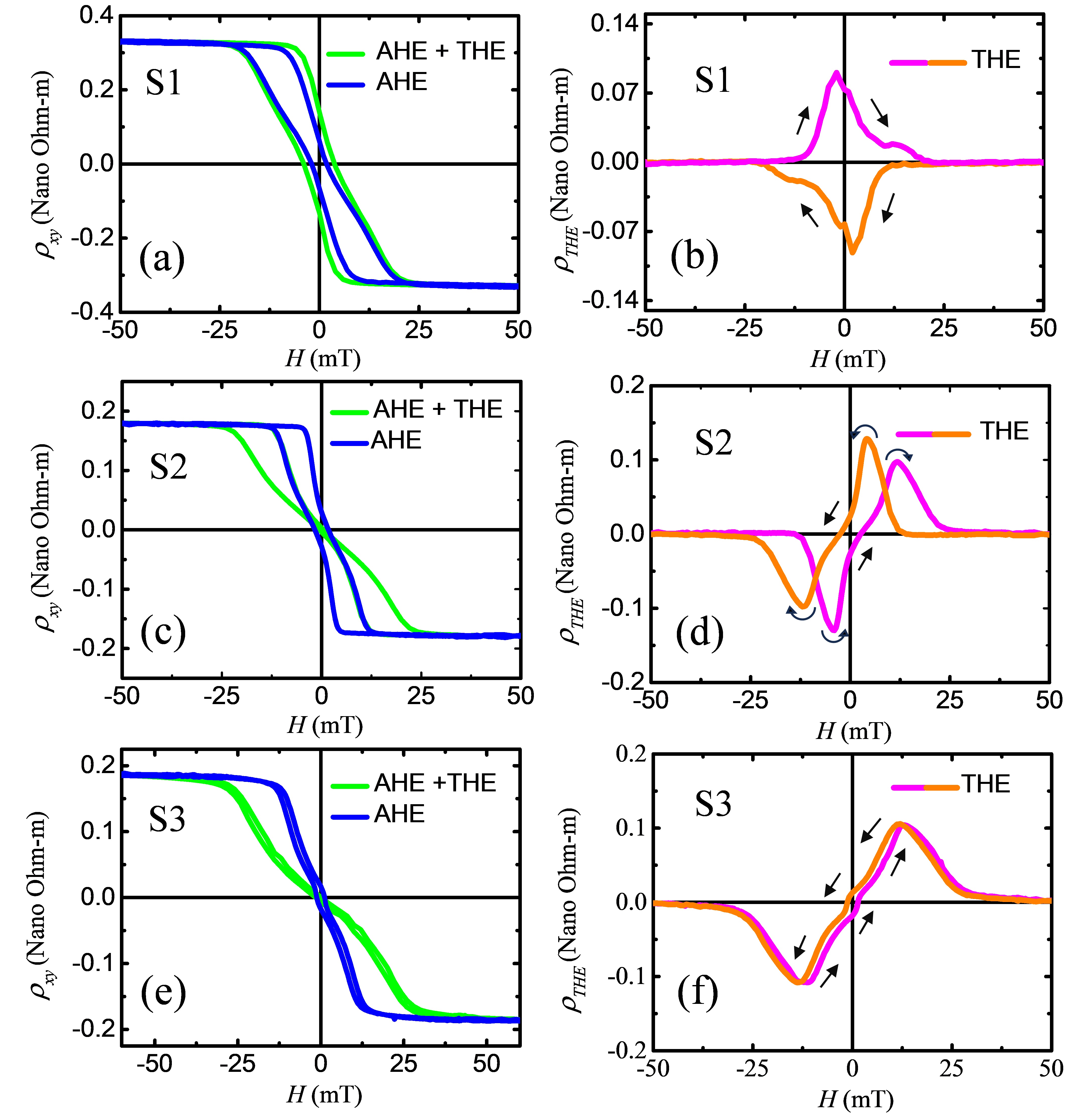
where and are the ordinary and anomalous Hall coefficients and is the out-of-plane magnetization as a function of the applied field (). Thus, can be extracted by subtracting the other two components from . Now, the OHE contribution has been eliminated from by fitting a linear function above 1.5 T, and the remaining (AHE + THE) components as a function of have been shown in figure 2(a), (c) and (e) for the samples S1, S2 and S3, respectively. At higher fields, the AHE contribution gets saturated and the can be deduced as, = 34, 33. Hence, the AHE components have been determined by scaling the loops with . Now, is quantified after subtracting the AHE contributions from the remaining resistivity. The as a function of field is shown in figure 2(b), (d), and (f) for samples S1, S2, and S3, respectively. A maximum of , , and 0.10 n m have been observed for samples S1, S2, and S3, respectively. The topological Hall resistivity confirms the presence of chiral spin textures in the samples. The is proportional to the average topological charge or skyrmion number 33, 35:
| (2) |

The average skyrmion number, , is the sum of the skyrmion numbers, , of all individual objects present in the sample. The topological Hall coefficient, , represents the density and spin-polarization of the carriers. The is defined as a product of vorticity () and core polarity () of the texture i.e. = 33, 36. The vorticity, = +1 for skyrmion. The defines the orientation of a core magnetic moment along the out-of-plane direction of a texture. The value of it is determined by considering the background magnetization. = +1 (-1) for a - (+) magnetized sample. So, depending upon the core polarity, , (+1 or -1), could be either +1 or -1 which basically defines two distinct phases of topological objects. It should be noted that during the field sweep from +ve to -ve saturation field (or vice versa), we have observed a single peak in for S1 (figure 2 (b)) which signifies only one type of texture. Whereas both a peak and a deep (in the rest of the manuscript we called it as double peak with opposite sign) have been noticed for the samples S2 (figure 2 (d)) and S3 (figure 2 (f)) during the field sweep. Now, a sign change in is only possible by changing the temperature. As all the measurements are performed at room temperature, for double peak, sign change in solely depends on . During the field sweep, the core polarity switches, hence, two distinct textures could be observed in this case (later in the manuscript, we have described in detail).
Additionally, from MFM scanning on S1, it has been found that the chiral textures are skyrmions. At a demagnetized state, a worm-like domain state is observed, as shown in Figure 3 (a). Further, increasing the field the worm-like domains start to contract (figure 3 (b)) and form isolated skyrmions as shown in Figure 3 (c-d). At higher fields, skyrmion density is reduced and finally, a saturated state is achieved. However, in samples S2 and S3, the domains become saturated due to the stray field of the MFM tip, which is the same tip used for sample S1 (MFM images are shown in Figure S2 of the supplementary information). This observation suggests that the samples containing the Re layer (S2 and S3) exhibit a lower pinning landscape than S1 [9].

Further, the reason behind the different shapes of (figure 2(b) and (d)) in samples S1 and S2 (or S3), has also been understood via micromagnetic simulations. Previously, this kind of a single peak 37, 38 and double peak (i.e., double peak with opposite sign) 22, 23, 39, 40 in resistivity were observed in different thin films. The emergence of a signal peak can be attributed to the presence of a singular type of topological object. Conversely, the manifestation of double peaks with opposite signs is indicative of the coexistence of two distinct phases (i.e. = +1 and -1) of a topological object [20,21,37,38]. Recently, P. K. sivakumar et al. explained that a double peak (with the same sign) in topological resistivity comes due to the presence of skyrmion and anti-skyrmion having the same topological charge in a MgO (001)/Mn2RhSn system 33. However, the precise conditions leading to the occurrence of either a single peak or a double peak (with opposite signs) in the Hall signature have not been thoroughly investigated. Thus, we have investigated the origin of such behaviour in via micromagnetic simulations. In our simulations, the magnetization of the system has been changed from +ve to -ve saturation state by varying the applied field with a small step. In every field value the average skyrmion number, , is calculated using the ‘’ command in Mumax3. As iDMI defines the chirality of a system, the iDMI value, , is varied in a range of 0.5-5.0 mJ/m3 considering = A/m and = 0.4 MJ/m3. From equation 2, it should be noted that corresponds to the of the system. A similar shape of the is reproduced from the simulation which reveals the underlying physics of the appearance of single or double peaks. Figure 4(a) shows the as a function of field. A single peak in has been observed for = 0.5 to 2.5 mJ/m3. Beyond = 2.5 mJ/m3, double peaks in became prominent. As seen, with enhancing , the maximum value of increases, and a transformation from single to double peak in occurs. Thus, is a very important parameter in deciding the nature .

For a single peak in (figure 5(a), considering = 2 mJ/m2 and = 0.4 MJ/m3), while the field has been reduced from a positive saturation, the reversed domain with = 0 is nucleated (see figure 5(b)). Further, by reducing the field the reverse domain expands (figure 5(c)) and is interconnected with neighbouring domains to form a worm-like structure (figure 5(d)). Now, the worm-like domain breaks into skyrmions with = +1 (figure 5(e)-(g)) with decreasing the field (i.e., increasing the field in -ve direction) and contributing to Hall resistivity. With a very higher field again oppositely saturated FM ground state has been achieved. Thus, it should be noted that the peak in or comes due to only one type of topological object.
In the case of a double peak, (figure 6(a), considering = 5 mJ/m2 and = 0.4 MJ/m3) while decreasing the field, several reverse nuclei occur in terms of chiral domain walls (DW), elongated skyrmions or skyrmions (due to presence of high iDMI) which contribute to = -1. With increasing the field in the reverse direction, the nuclei expand and merge with nearby topological objects and a chiral worm-like domain phase is achieved giving a maximum value = -17 (figure 6(e)). Further, with the field, the worm phase again breaks into skyrmions with opposite polarity i.e., = +1 (figure 6 (f)), and finally, a state with maximum isolated skyrmion ( = +38) is achieved (figure 6(h)). Therefore, the double peak in or is formed by the contribution of two topological objects with opposite polarity.

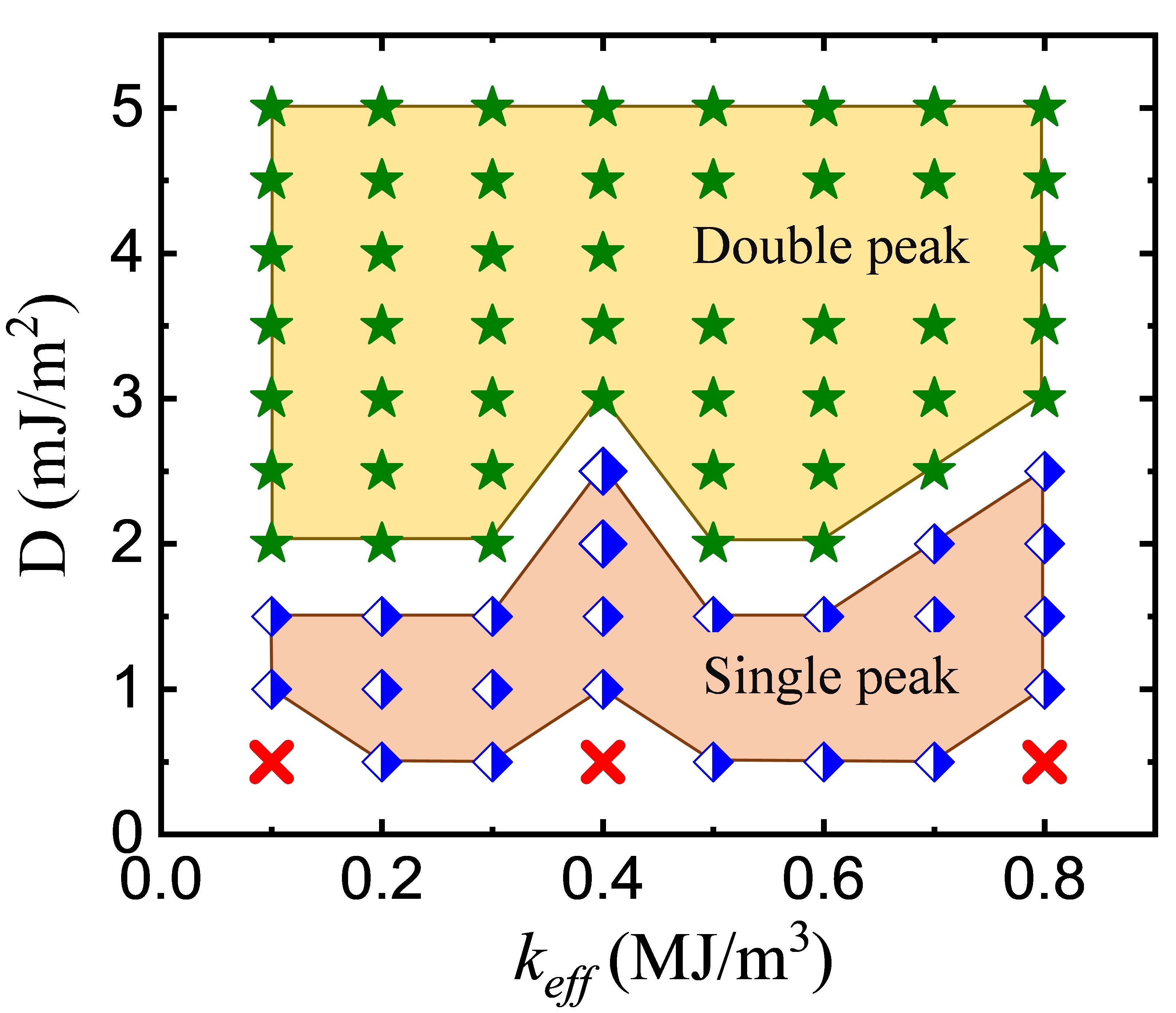
So far, we have investigated the effect of on or . However, the anisotropy of the system plays a major role in deciding the minimum energy state which helps to stabilize a chiral texture in a system. Thus, is also varied in the simulation over a range of 0.1- 0.8 MJ/m3 and found that the shape of the also depends on it. A phase plot of vs has been shown in Figure 7. As observed, the shape of or depends on both the parameter and and using a proper combination of them, a single to double peak transition in can be achieved. From the above discussion, it could be concluded that the existence of relatively low iDMI induces a single peak in for the Pt/Co/Ta sample whereas double peaks arise in Pt/Co/Re samples due to the presence of higher iDMI.
4 Conclusion
In summary, the THE has been observed in both Pt/Co/Ta and Pt/Co/Re systems indicating the existence of skyrmions which is confirmed via MFM. A maximum of 0.08 and 0.12 n-m has been observed for sample Pt/Co/Ta and Pt/Co/Re, respectively. Two different natures of topological Hall resistivity are observed in the samples. As seen, the effective anisotropy () and DMI interaction play a pivotal role in determining THE signal in a system. By choosing a proper combination of and iDMI value () of a system, one can achieve single to double peak transition.
5 Acknowledgement
The authors would like to thank Dr. Esita Pandey for the valuable discussion and help during manuscript preparation. The authors also thank the Department of Atomic Energy (DAE) of India, the Indo-French collaborative project supported by CEFIPRA (IFC/5808-1/2017), and DST-SERB (Grant No. CRG/2021/001245) for financial support.
References
- Fert et al. 2017 Fert, A.; Reyren, N.; Cros, V. Magnetic skyrmions: advances in physics and potential applications. Nature Reviews Materials 2017, 2, 17031
- Everschor-Sitte et al. 2018 Everschor-Sitte, K.; Masell, J.; Reeve, R. M.; Kläui, M. Perspective: Magnetic skyrmions—Overview of recent progress in an active research field. Journal of Applied Physics 2018, 124
- Fert et al. 2013 Fert, A.; Cros, V.; Sampaio, J. Skyrmions on the track. Nature nanotechnology 2013, 8, 152–156
- Luo and You 2021 Luo, S.; You, L. Skyrmion devices for memory and logic applications. APL Materials 2021, 9
- Tomasello et al. 2014 Tomasello, R.; Martinez, E.; Zivieri, R.; Torres, L.; Carpentieri, M.; Finocchio, G. A strategy for the design of skyrmion racetrack memories. Scientific reports 2014, 4, 1–7
- Jiang et al. 2015 Jiang, W.; Upadhyaya, P.; Zhang, W.; Yu, G.; Jungfleisch, M. B.; Fradin, F. Y.; Pearson, J. E.; Tserkovnyak, Y.; Wang, K. L.; Heinonen, O.; others Blowing magnetic skyrmion bubbles. Science 2015, 349, 283–286
- Moreau-Luchaire et al. 2016 Moreau-Luchaire, C.; Moutafis, C.; Reyren, N.; Sampaio, J.; Vaz, C. A. F.; Horne, N. V.; Bouzehouane, K.; Garcia, K.; Deranlot, C.; Warnicke, P.; others Additive interfacial chiral interaction in multilayers for stabilization of small individual skyrmions at room temperature. Nature nanotechnology 2016, 11, 444–448
- Hrabec et al. 2017 Hrabec, A.; Belmeguenai, M.; Stashkevich, A.; Chérif, S. M.; Rohart, S.; Roussigné, Y.; Thiaville, A. Making the Dzyaloshinskii-Moriya interaction visible. Applied Physics Letters 2017, 110, 242402
- Ojha et al. 2023 Ojha, B.; Mallick, S.; Panigrahy, S.; Sharma, M.; Thiaville, A.; Rohart, S.; Bedanta, S. Driving skyrmions with low threshold current density in Pt/CoFeB thin film. Physica Scripta 2023, 98, 35819
- Bogdanov and Hubert 1994 Bogdanov, A.; Hubert, A. Thermodynamically stable magnetic vortex states in magnetic crystals. Journal of magnetism and magnetic materials 1994, 138, 255–269
- Bogdanov and Panagopoulos 2020 Bogdanov, A. N.; Panagopoulos, C. Physical foundations and basic properties of magnetic skyrmions. Nature Reviews Physics 2020, 2, 492–498
- Romming et al. 2015 Romming, N.; Kubetzka, A.; Hanneken, C.; von Bergmann, K.; Wiesendanger, R. Field-dependent size and shape of single magnetic skyrmions. Physical review letters 2015, 114, 177203
- Heinze et al. 2011 Heinze, S.; Bergmann, K. V.; Menzel, M.; Brede, J.; Kubetzka, A.; Wiesendanger, R.; Bihlmayer, G.; Blügel, S. Spontaneous atomic-scale magnetic skyrmion lattice in two dimensions. nature physics 2011, 7, 713–718
- Woo et al. 2018 Woo, S.; Song, K. M.; Zhang, X.; Zhou, Y.; Ezawa, M.; Liu, X.; Finizio, S.; Raabe, J.; Lee, N. J.; Kim, S.-I.; others Current-driven dynamics and inhibition of the skyrmion Hall effect of ferrimagnetic skyrmions in GdFeCo films. Nature communications 2018, 9, 959
- Woo et al. 2016 Woo, S.; Litzius, K.; Krüger, B.; Im, M.-Y.; Caretta, L.; Richter, K.; Mann, M.; Krone, A.; Reeve, R. M.; Weigand, M.; others Observation of room-temperature magnetic skyrmions and their current-driven dynamics in ultrathin metallic ferromagnets. Nature materials 2016, 15, 501–506
- Legrand et al. 2020 Legrand, W.; Maccariello, D.; Ajejas, F.; Collin, S.; Vecchiola, A.; Bouzehouane, K.; Reyren, N.; Cros, V.; Fert, A. Room-temperature stabilization of antiferromagnetic skyrmions in synthetic antiferromagnets. Nature materials 2020, 19, 34–42
- Wu et al. 2020 Wu, Y.; Zhang, S.; Zhang, J.; Wang, W.; Zhu, Y. L.; Hu, J.; Yin, G.; Wong, K.; Fang, C.; Wan, C.; others Néel-type skyrmion in WTe2/Fe3GeTe2 van der Waals heterostructure. Nature communications 2020, 11, 3860
- Schulz et al. 2012 Schulz, T.; Ritz, R.; Bauer, A.; Halder, M.; Wagner, M.; Franz, C.; Pfleiderer, C.; Everschor, K.; Garst, M.; Rosch, A. Emergent electrodynamics of skyrmions in a chiral magnet. Nature Physics 2012, 8, 301–304
- Kanazawa et al. 2011 Kanazawa, N.; Onose, Y.; Arima, T.; Okuyama, D.; Ohoyama, K.; Wakimoto, S.; Kakurai, K.; Ishiwata, S.; Tokura, Y. Large topological Hall effect in a short-period helimagnet MnGe. Physical review letters 2011, 106, 156603
- Huang and Chien 2012 Huang, S. X.; Chien, C. L. Extended skyrmion phase in epitaxial FeGe (111) thin films. Physical review letters 2012, 108, 267201
- Neubauer et al. 2009 Neubauer, A.; Pfleiderer, C.; Binz, B.; Rosch, A.; Ritz, R.; Niklowitz, P. G.; Böni, P. Topological Hall effect in the A phase of MnSi. Physical review letters 2009, 102, 186602
- Soumyanarayanan et al. 2017 Soumyanarayanan, A.; Raju, M.; Oyarce, A. L. G.; Tan, A. K. C.; Im, M.-Y.; Petrović, A. P.; Ho, P.; Khoo, K. H.; Tran, M.; Gan, C. K.; others Tunable room-temperature magnetic skyrmions in Ir/Fe/Co/Pt multilayers. Nature materials 2017, 16, 898–904
- He et al. 2018 He, M.; Li, G.; Zhu, Z.; Zhang, Y.; Peng, L.; Li, R.; Li, J.; Wei, H.; Zhao, T.; Zhang, X.-G.; others Evolution of topological skyrmions across the spin reorientation transition in Pt/Co/Ta multilayers. Physical Review B 2018, 97, 174419
- Mourkas et al. 2021 Mourkas, A.; Markou, A.; Swekis, P.; Panagiotopoulos, I. Topological hall effect in Pt/Co/W multilayers with different anisotropies. Journal of Magnetism and Magnetic Materials 2021, 530, 167937
- Jadaun et al. 2020 Jadaun, P.; Register, L. F.; Banerjee, S. K. The microscopic origin of DMI in magnetic bilayers and prediction of giant DMI in new bilayers. npj Computational Materials 2020, 6, 88
- Fakhredine et al. 2024 Fakhredine, A.; Wawro, A.; Autieri, C. Huge Dzyaloshinskii–Moriya interactions in Pt/Co/Re thin films. Journal of Applied Physics 2024, 135
- Nomura et al. 2022 Nomura, A.; Gao, T.; Haku, S.; Ando, K. Additive Dzyaloshinskii–Moriya interaction in Pt/Co/Re films. AIP Advances 2022, 12
- Behera et al. 2018 Behera, A. K.; Mishra, S. S.; Mallick, S.; Singh, B. B.; Bedanta, S. Size and shape of skyrmions for variable Dzyaloshinskii–Moriya interaction and uniaxial anisotropy. Journal of Physics D: Applied Physics 2018, 51, 285001
- Belmeguenai et al. 2015 Belmeguenai, M.; Adam, J.-P.; Roussigné, Y.; Eimer, S.; Devolder, T.; Kim, J.-V.; Cherif, S. M.; Stashkevich, A.; Thiaville, A. Interfacial Dzyaloshinskii-Moriya interaction in perpendicularly magnetized Pt/Co/AlOx ultrathin films measured by Brillouin light spectroscopy. Physical Review B 2015, 91, 180405
- Shahbazi et al. 2019 Shahbazi, K.; Kim, J.-V.; Nembach, H. T.; Shaw, J. M.; Bischof, A.; Rossell, M. D.; Jeudy, V.; Moore, T. A.; Marrows, C. H. Domain-wall motion and interfacial Dzyaloshinskii-Moriya interactions in Pt/Co/Ir (t Ir)/Ta multilayers. Physical Review B 2019, 99, 94409
- Kashid et al. 2014 Kashid, V.; Schena, T.; Zimmermann, B.; Mokrousov, Y.; Blügel, S.; Shah, V.; Salunke, H. G. Dzyaloshinskii-Moriya interaction and chiral magnetism in 3 d- 5 d zigzag chains: Tight-binding model and ab initio calculations. Physical Review B 2014, 90, 54412
- Vansteenkiste et al. 2014 Vansteenkiste, A.; Leliaert, J.; Dvornik, M.; Helsen, M.; Garcia-Sanchez, F.; Waeyenberge, B. V. The design and verification of MuMax3. AIP advances 2014, 4
- Sivakumar et al. 2020 Sivakumar, P. K.; Göbel, B.; Lesne, E.; Markou, A.; Gidugu, J.; Taylor, J. M.; Deniz, H.; Jena, J.; Felser, C.; Mertig, I.; others Topological Hall signatures of two chiral spin textures hosted in a single tetragonal inverse Heusler thin film. ACS nano 2020, 14, 13463–13469
- Li et al. 2019 Li, Y.; Zhang, L.; Zhang, Q.; Li, C.; Yang, T.; Deng, Y.; Gu, L.; Wu, D. Emergent topological Hall effect in La0. 7Sr0. 3MnO3/SrIrO3 heterostructures. ACS applied materials and interfaces 2019, 11, 21268–21274
- Raju et al. 2021 Raju, M.; Petrović, A. P.; Yagil, A.; Denisov, K. S.; Duong, N. K.; Göbel, B.; Şaşoğlu, E.; Auslaender, O. M.; Mertig, I.; Rozhansky, I. V.; others Colossal topological Hall effect at the transition between isolated and lattice-phase interfacial skyrmions. Nature Communications 2021, 12, 2758
- Rohart and Thiaville 2013 Rohart, S.; Thiaville, A. Skyrmion confinement in ultrathin film nanostructures in the presence of Dzyaloshinskii-Moriya interaction. Physical Review B 2013, 88, 184422
- Li et al. 2020 Li, P.; Ding, J.; Zhang, S. S.-L.; Kally, J.; Pillsbury, T.; Heinonen, O. G.; Rimal, G.; Bi, C.; DeMann, A.; Field, S. B.; others Topological Hall effect in a topological insulator interfaced with a magnetic insulator. Nano letters 2020, 21, 84–90
- Meng et al. 2018 Meng, K. K.; Zhao, X. P.; Liu, P. F.; Liu, Q.; Wu, Y.; Li, Z. P.; Chen, J. K.; Miao, J.; Xu, X. G.; Zhao, J. H.; others Robust emergence of a topological Hall effect in MnGa/heavy metal bilayers. Physical Review B 2018, 97, 60407
- Budhathoki et al. 2020 Budhathoki, S.; Sapkota, A.; Law, K. M.; Ranjit, S.; Nepal, B.; Hoskins, B. D.; Thind, A. S.; Borisevich, A. Y.; Jamer, M. E.; Anderson, T. J.; others Room-temperature skyrmions in strain-engineered FeGe thin films. Physical Review B 2020, 101, 220405
- Ahmed et al. 2019 Ahmed, A. S.; Lee, A. J.; Bagués, N.; McCullian, B. A.; Thabt, A. M. A.; Perrine, A.; Wu, P.-K.; Rowland, J. R.; Randeria, M.; Hammel, P. C.; others Spin-Hall topological Hall effect in highly tunable Pt/ferrimagnetic-insulator bilayers. Nano letters 2019, 19, 5683–5688