Modulation transfer protocol for Rydberg RF receivers
Abstract
We propose and demonstrate a modulation transfer protocol to increase the detection sensitivity of a Rydberg RF receiver to fields out of resonance from the transition between Rydberg levels. This protocol is based on a phase modulation of the control field used to create the Electromagnetically Induced Transparency (EIT) signal. The nonlinear wave-mixing of the multi-component coupling laser and the probe laser transfers the modulation to the probe laser, which is used for RF-field detection. The measurements compare very well to semi-classical simulations of atom-light interaction and show an improvement in the RF bandwidth of the sensor and an improved sensitivity of the response to weak fields.
Research on RF receivers based on optical detection methods using thermal Rydberg atoms has strongly developed in the last decade. From a three-level EIT scheme in Rubidium 87 (87Rb) vapor, this RF detection method based on the induced Autler-Townes splitting of Rydberg levels has been expanded to Rubidium 85 (85Rb), Cesium (Cs) vapors Sedlacek2012 ; Fan2015 ; Kumar2017 ; Holloway2014 and four-level EIT schemesBrown2023 ; Chen2022 ; Thaicharoen2019 ; Bohaichuk2023 . It is capable of detecting the signal from the sub-Gigahertz range Brown2023 to Terahertz frequenciesChen2022 using the numerous allowed atomic transitions between Rydberg states in alkali atoms Chopinaud2021 . The large electric dipole moments of these transitions make Rydberg RF receivers very sensitive to resonant microwave fields, with sensitivities in the range of in the frequency range. However, the signal quickly decreases when the detuning of the RF signal from the atomic transition increases. An RF reference field serving as a local oscillator can help retrieve more sensitivity Simons2019 ; Jing2020 ; Yao2022 , but this method is more cumbersome and requires an auxiliary antenna, which prevents the system from being purely dielectric and can, therefore, induce RF field distortion.
We propose an all-optical method based on a modulation transfer by four-wave mixing in the atomic medium Ducloy1982 , which improves the sensitivity of the atom-based RF receiver to detuned fields. Although such a modulation transfer method is popular for laser frequency stabilization using two-level systems MTS2008 ; Preuschoff2018 ; Sun2016 , there are very few experimental demonstrations of this technique applied to three- or four-level systemsLim2022 . Here, we consider such a modulation transfer method in the case of a three-level ladder EIT phenomenon in 85Rb and investigate its capability of increasing the detection bandwidth of the corresponding Rydberg RF receiver.
In the present letter, we thus implement both the conventional and the modulation transfer protocols and compare their responses to RF fields with different detunings. We focus on the low-field domain where the Autler-Townes (AT) splitting is hardly visible, and we interpret the experimental results with numerical simulation.
We use 85Rb, which has the highest abundance in a natural mixture of 85 and 87 isotopes. A probe laser around 780 couples its ground state [\ce5^2S_1/2()] to the intermediate state [\ce5^2P_3/2()] (Fig. 1. (a)). A 480 laser couples this intermediate state manifold to the Rydberg state [\ce50^2D_5/2()]. We couple this Rydberg state to the state [\ce51^2P_3/2()] with the RF field around 17.0424 that we wish to detetct.
In the conventional protocol, the probe and coupling laser beams are single-frequency fields and can be modeled by (see Fig. 1. (b)). The transmitted probe beam after the vapor cell then remains single-frequency and can be written
In the modulation transfer protocol, the coupling laser is phase-modulated and exhibits sidebands with opposite signs (see Fig. 1. (c)):
| (1) |
where is the modulation frequency. Close to EIT resonance, the modulation is transferred from the coupling beam to the probe beam via the atomic medium nonlinearities so that one now expects the transmitted probe laser output to also exhibit sidebands at from the carrier:
| (2) |
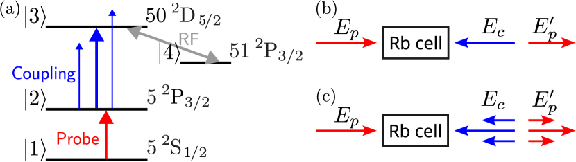
Figure 2 schematizes the experimental setup used to test this idea. The probe and coupling lasers counter-propagate through a quartz cell containing a natural mixture of Rubidium (with 73% of \ce^85Rb and 27% of \ce^87Rb) at room temperature. Inside the cell, the probe (coupling) beam has a waist diameter of 0.3 (0.4) with an 11.5 (14.5) Rayleigh length, which is longer than the 7.5 vapor cell length. The probe input power is 0.4 , and the coupling one is 54 . A horn antenna (MVG QR18000) is placed 57.5 away from the vapor cell and emits an RF field perpendicularly to the laser path. RF absorbing panels isolate the antenna and the vapor cell from other elements. The probe, coupling, and RF fields are linearly polarized along , so that all the magnetic sub-levels between the two Rydberg states are coupled Sedlacek2013 .

We use a Toptica tunable diode laser to provide the 780 probe laser and a Toptica amplified and frequency-doubled tunable diode laser (TA-SHG) system to generate the 480 coupling laser. The probe laser is stabilized by Modulation Transfer Spectroscopy MTS2008 on the atomic frequency that corresponds to the transition between the levels and . Using an auxiliary cell, the coupling laser is then locked using the EIT resonance in the ladder system Abel2009 , which enforces the condition , where is the frequency difference between the atomic levels and . Considering the RF frequency value, which gives a symmetrical AT splitting, we obtain for the RF transition between the levels and . The RF signal is provided by a R&S SMF100A signal generator, and the RF electric field amplitude at the vapor cell position is estimated after taking into account cable and insertion losses, the gain of the antenna and its distance to the vapor cell. The cell perturbation factor Robinson2021a , which decreases the average RF field inside the cell, is estimated to be about 0.6 from a finite-difference time-domain (FDTD) electromagnetic simulation around 17 with our vapor cell.

Let us now examine the signal obtained with the conventional and modulation transfer protocols as a function of probe laser detuning . We scan the probe laser frequency around by 100 thanks to two double-pass acousto-optic modulators (AOM) Donley2005 . The AOMs are driven by VCOs, with a 10 scanning rate. A fast APD (Thorlabs APD410A/M) of 10 instantaneous bandwidth and sensitivity at 780 detects the probe laser after the vapor cell. Another photodetector monitors the probe laser before the vapor cell so that we can record the corresponding background. We average the received signal over 128 scanning rounds to reduce electronic noise. Knowing the photodetector sensitivity and the electronic attenuation, we can derive the probe laser transmission from the probe input and output intensities. We can then compute the probe transparency by subtracting the probe laser transmission from the one measured without any coupling laser. One example of such an EIT transparency signal in the presence of a weak resonant RF field is plotted in Fig. 3(a), together with the result of the corresponding simulation in Fig. 3(c).
These simulations are obtained by the density matrix formalism using an effective four-level atomic system Holloway2017 . Rabi frequencies are derived considering the effective electric dipole elements for linear transitions between Zeeman sublevels (). The electric dipole elements and decay rates for the first transition () are taken from well-established data Steck2023 . For the second () and third () transitions, we obtain these parameters from an open-source Python package Sibalic2017 ; Robertson2021 . To take into account the atomic medium optical thickness Rotunno2023 (linear transmission equal to 0.41), we divide the cell into a hundred layers, for which the thin medium approximation can be considered valid. We include the Doppler effect of the thermal vapor by integrating over velocity classes, and the transit rate of atoms through the laser beam by corresponding decay and feeding rates Finkelstein2023 . The simulation results, shown in Figs. 3(c) and (d), are in very good agreement with the measurements for both protocols, which validates our theoretical approach. In order to simulate the modulation transfer protocol, a Floquet expansion and the continued fraction method Papademetriou1992 ; Wong2004 allow handling the oscillating terms in the optical Bloch equations.
Now, to implement the modulation transfer protocol experimentally, we need to modulate the phase of the coupling beam. To this aim, the coupling beam travels through two single-pass AOMs. The first one shifts the coupling light frequency by . The second one is driven by a signal at 180 with a phase modulation at a smaller frequency . It thus shifts the light frequency by 180 but also imprints a phase modulation at frequency Li2005 on it. The coupling laser thus exhibits two opposite sidebands at from the carrier (see Eq. Modulation transfer protocol for Rydberg RF receivers). Thanks to the 16 phase-modulation bandwidth of the AOM and the 10 instantaneous bandwidth of the photodetector, we could test several phase modulation frequencies . The phase modulation amplitude of the RF signal injected into the AOM is . A scanning Fabry-Perot interferometer allowed to measure a 0.6 ratio between the amplitudes of the sidebands and the carrier.
Once the transmitted probe beam and its intensity modulation are detected, we demodulate the signal at and filter it to obtain the relative modulation amplitude (RMA), which is defined as . This demodulation and filtering is performed with an analog electronic circuit. Figure 3(b) shows a typical RMA signal evolution versus probe detuning in the presence of the RF field. The signal of Fig. 3(b) now contains many more features than the usual DC signal of Fig. 3(a), which we will exploit in the following. Notice also that the signal of Fig. 3(b) is in excellent agreement with the simulations of Fig. 3(d).
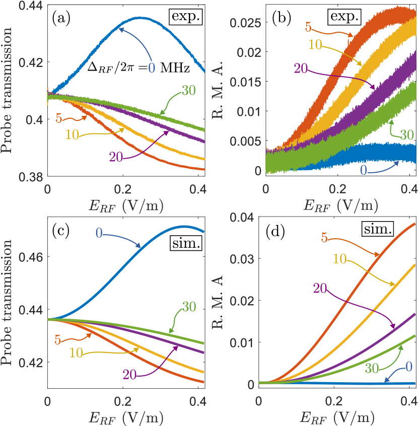
Let us now investigate the system response to RF fields at different RF detunings . In the following, for both protocols, the probe laser detuning is fixed, and the RF electric field amplitude is scanned at a rate of 10 . A fast oscilloscope characterizes the amplitude-modulated RF field to ensure that the modulation parameters provide a linear scan. Different sets of data were recorded for , and for . We choose to reproduce here those corresponding to the probe detuning, which gives the best sensitivity for detuned RF fields () for each protocol. Figures 4(a) and (b) thus show the results obtained for for the conventional protocol and for the modulation transfer one. The corresponding simulations (Figs. 4(c) and (d)) accurately reproduce the behavior of the system.
When the RF field is at resonance, it is clear that the conventional protocol gives the best sensitivity to variations of the RF field amplitude: the slope of the blue curve of Fig. 4(a) is very large. However, as soon as the RF field is detuned by a few MHz, the response of this signal to variations of becomes very flat (see the curves for in Fig. 4(a)), indicating a poor sensitivity of the standard protocol to detuned RF field variations. On the contrary, the signal obtained from the modulation transfer protocol (see the curves for in Fig. 4(b)) exhibits a strong slope for RF detunings even as large as 30 . Moreover, the comparison with the simulations of Figs. 4(c,d) is very accurate and confirms the apparent superiority of the modulation transfer protocol for detuned RF field detection.
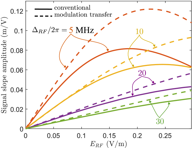
Since the comparison with the experiments shows that our simulations are accurate, we rely on those simulations to characterize more quantitatively the detection sensitivity of very weak detuned RF fields. This is also more convenient because our experiment takes place in an electromagnetically noisy environment, in which we can never reach an RF field close to zero. We thus derive the signal slope amplitudes from the simulation data of Figs. 4(c) and (d).
Figure 5 compares such slopes for different RF detunings for both protocols. The slope obtained by the modulation transfer protocol is always larger than the one obtained with standard DC signals. Moreover, the response of the modulation transfer protocol is better for a larger range of RF field amplitudes than the one of the standard protocol. This clearly indicates that the new protocol proposed here can provide an improvement in RF detection systems compared with the standard approach.
In this article, we have thus proposed and demonstrated an RF detection method using Rydberg-EIT in the presence of phase modulation of the coupling beam. We have shown theoretically and experimentally that this modulation is transferred to the probe beam in the presence of EIT, and that, once demodulated, the probe modulation can improve the sensitivity of an EIT-based Rydberg RF receiver to weak and detuned fields. With our parameters, the transfer of modulation to the probe provides a new response to the RF field, leading to a higher sensitivity for small RF fields observed for detunings as large . Moreover, the response of the modulation transfer protocol is shown to be more sensitive than the standard one over a larger range of field amplitudes. Another potential application is to tailor a constant sensitivity by using a quadrature with a well-chosen modulation configuration. Our experimental results are well-reproduced by simulations, so modulation parameters can be adapted to slightly different cases, corresponding to another alkali atom or other Rydberg levels.
We thank Joseph Delpy and Antoine Browaeys for fruitful discussions and Sébastien Rousselot for technical support.
This work was funded by the French Defense Innovation Agency, Quantum Saclay, and the European Defence Fund (EDF) under grant agreement EDF-2021-DIS-RDIS-ADEQUADE (n°101103417).
DATA AVAILABILITY
The data that support the findings of this study are available from the corresponding author upon reasonable request.
References
- (1) J. A. Šedlaćek, A. Schwettmann, H. Kübler, R. Löw, T. Pfau, and J. P. Shaffer, Microwave electrometry with Rydberg atoms in a vapour cell using bright atomic resonances, Nature Physics 8, 819–824 (2012).
- (2) H. Fan, S. Kumar, J. Sheng, J. P. Shaffer, C. L. Holloway, and J. A. Gordon, Effect of vapor-cell geometry on Rydberg-atom-based measurements of radio-frequency electric fields, Phys. Rev. Applied 4, 044015 (2015).
- (3) S. Kumar, H. Fan, H. Kübler, J. Sheng, and J. P. Shaffer, Atom-based sensing of weak radio frequency electric fields using homodyne readout, Scientific Reports 7, 42981 (2017).
- (4) C. L. Holloway, J. A. Gordon, S. Jefferts, A. Schwarzkopf, D. A. Anderson, S. A. Miller, N. Thaicharoen, and G. Raithel Broadband Rydberg atom- based electric-field probe for SI-traceable, self-calibrated measurements, IEEE Transactions on Antennas and Propagation 62, 6169–6182 (2014).
- (5) R. C. Brown, B. Kayim, M. A. Viray, A. R. Perry, B. C. Sawyer, and R. Wyllie Very-high- and ultrahigh-frequency electric-field detection us- ing high angular momentum Rydberg states, Physical Review A 107, 052605 (2023).
- (6) S. Chen, D. J. Reed, A. R. MacKellar, L. A. Downes, N. F. A. Almuhawish, M. J. Jamieson, C. S. Adams, and K. J. Weatherill, Terahertz electrometry via infrared spectroscopy of atomic vapor,, Optica 9, 485–491 (2022).
- (7) N. Thaicharoen, K. R. Moore, D. A. Anderson, R. C. Powel, E. Peterson, and G. Raithel, Electromagnetically induced transparency, absorption, and microwave-field sensing in a Rb vapor cell with a three-color all-infrared laser system, Physical Review A 100, 063427 (2019).
- (8) S. M. Bohaichuk, F. Ripka, V. Venu, F. Christaller, C. Liu, M. Schmidt, H. Kübler, and J. P. Shaffer, Three-photon Rydberg-atom-based radio- frequency sensing scheme with narrow linewidth, Physical Review Applied 20, L061004 (2023).
- (9) A. Chopinaud and J. Pritchard, Optimal state choice for Rydberg-atom microwave sensors, Physical Review Applied 16, 024008 (2021).
- (10) M. T. Simons, A. H. Haddab, J. A. Gordon, and C. L. Holloway, A Rydberg atom-based mixer: Measuring the phase of a radio frequency wave, Applied Physics Letters 114, 114101 (2019).
- (11) M. Jing, Y. Hu, J. Ma, H. Zhang, L. Zhang, L. Xiao, and S. Jia, Atomic superheterodyne receiver based on microwave-dressed Rydberg spectroscopy, Nature Physics 16, 911–915 (2020).
- (12) J. Yao, Q. An, Y. Zhou, K. Yang, F. Wu, and Y. Fu, Sensitivity enhancement of far-detuned RF field sensing based on Rydberg atoms dressed by a near-resonant rf field, Optics Letters 47, 5256–5259 (2022).
- (13) M. Ducloy and D. Bloch, Theory of degenerate four-wave mixing in resonant Doppler-broadened media. - II. Doppler-free heterodyne spectroscopy via collinear four-wave mixing in two- and three-level systems, Journal de Physique 43, 57–65 (1982).
- (14) D. J. McCarron, S. A. King, and S. L. Cornish, Modulation transfer spectroscopy in atomic Rubidium, Measurement Science and Technology 19, 105601 (2008).
- (15) T. Preuschoff, M. Schlosser, and G. Birkl, Optimization strategies for modulation transfer spectroscopy applied to laser stabilization, Optics Express 26, 24010–24019 (2018).
- (16) D. Sun, C. Zhou, L. Zhou, J. Wang, and M. Zhan, Modulation transfer spectroscopy in a Lithium atomic vapor cell, Optics Express 24, 10649–10662 (2016).
- (17) M. J. Lim, S. McPoyle, and M. Cervantes, Modulation transfer spectroscopy of a four-level ladder system in atomic Rubidium, Optics Communications 522, 128651 (2022).
- (18) J. A. Sedlacek, A. Schwettmann, H. Kübler, and J. P. Shaffer, Atom-based vector microwave electrometry using rubidium Rydberg atoms in a vapor cell, Physical Review Letters 111, 063001 (2013).
- (19) R. P. Abel, A. K. Mohapatra, M. G. Bason, J. D. Pritchard, K. J. Weatherill, U. Raitzsch, and C. S. Adams, Laser frequency stabilization to excited state transitions using electromagnetically induced transparency in a cascade system, Applied Physics Letters 94, 071107 (2009).
- (20) A. K. Robinson, A. B. Artusio-Glimpse, M. T. Simons, and C. L. Holloway, Atomic spectra in a six-level scheme for electromagnetically induced transparency and Autler-Townes splitting in Rydberg atoms, Physical Review A 103, 023704 (2021).
- (21) E. A. Donley, T. P. Heavner, F. Levi, M. O. Tataw, and S. R. Jefferts, Double-pass acousto-optic modulator system, Review of Scientific Instruments 76, 063112 (2005).
- (22) C. L. Holloway, M. T. Simons, J. A. Gordon, A. Dienstfrey, D. A. Anderson, and G. Raithel, Electric field metrology for si traceability: Systematic measurement uncertainties in electromagnetically induced transparency in atomic vapor, Journal of Applied Physics 121, 233106 (2017).
- (23) D. A. Steck, Rubidium 85 D line data, Available online at https://steck.us/alkalidata/ (2001), revision 2.3.2, 10 September 2023.
- (24) N. Šibalić, J. Pritchard, C. Adams, and K. Weatherill, Arc: An open-source library for calculating properties of alkali Rydberg atoms, Computer Physics Communications 220, 319–331 (2017).
- (25) E. Robertson, N. Šibalić, R. Potvliege, and M. Jones, Arc 3.0: An expanded Python toolbox for atomic physics calculations, Computer Physics Communications 261, 107814 (2021).
- (26) A. P. Rotunno, C. L. Holloway, N. Prajapati, S. Berweger, A. B. Artusio-Glimpse, R. Brown, M. Simons, A. K. Robinson, B. N. Kayim, M. A. Viray, J. F. Jones, B. C. Sawyer, R. Wyllie, T. Walker, R. W. Ziolkowski, S. R. Jefferts, S. Geibel, J. Wheeler, and E. Imhof, Investigating electromagnetically induced transparency spectral lineshape distortion due to non- uniform fields in Rydberg-atom electrometry, Journal of Applied Physics 134, 084401 (2023).
- (27) R. Finkelstein, S. Bali, O. Firstenberg, and I. Novikova, A practical guide to electromagnetically induced transparency in atomic vapor, New Journal of Physics 25, 035001 (2023).
- (28) S. Papademetriou, S. Chakmakjian, and C. R. Stroud, Optical subharmonic Rabi resonances, Journal of the Optical Society of America B 9, 1182–1188 (1992).
- (29) V. Wong, R. S. Bennink, A. M. Marino, R. W. Boyd, C. R. Stroud, and F. A. Narducci, Influence of coherent Raman scattering on coherent population trapping in atomic sodium vapor, Physical Review A 70, 053811 (2004).
- (30) E. Li, J. Yao, D. Yu, J. Xi, and J. Chicharo, Optical phase shifting with acousto-optic devices, Optics Letters 30, 189–191 (2005).