Laser wakefield acceleration of ions with a transverse flying focus
Abstract
The extreme electric fields created in high-intensity laser-plasma interactions could generate energetic ions far more compactly than traditional accelerators. Despite this promise, laser-plasma accelerators have remained stagnant at maximum ion energies of 100 MeV/nucleon for the last twenty years. The central challenge is the low charge-to-mass ratio of ions, which has precluded one of the most successful approaches used for electrons: laser wakefield acceleration. Here we show that a laser pulse with a focal spot that moves transverse to the laser propagation direction enables wakefield acceleration of ions to GeV energies in underdense plasma. Three-dimensional particle-in-cell simulations demonstrate that this relativistic-intensity “transverse flying focus” can trap ions in a comoving electrostatic pocket, producing a monoenergetic collimated ion beam. With a peak intensity of W/cm2 and an acceleration distance of 0.44 cm, we observe a proton beam with 23.1 pC charge, 1.6 GeV peak energy, and 3.7% relative energy spread. This approach allows for compact high-repetition-rate production of high-energy ions, highlighting the capability of more generalized spatio-temporal pulse shaping to address open problems in plasma physics.
I Introduction
Beams of energetic ions have applications ranging from particle [1] and nuclear physics [2] to laboratory astrophysics [3], high-energy-density science [4], and medicine [5]. The standard approach for producing energetic ion beams, the radio-frequency accelerator, switches the polarity of electric fields in metallic cavities to continuously accelerate the ions. The gradients of these accelerators are fundamentally limited to 100 MeV/m by radio-frequency breakdown [6], so they must be hundreds of meters long to produce relativistic ions. This has motivated efforts to build advanced compact ion accelerators based on laser-driven plasma approaches, where acceleration gradients can be three orders-of-magnitude higher (100 GeV/m) [7, 8].
Several distinct mechanisms have been proposed for ion acceleration in a plasma, the most established of which is target normal sheath acceleration (TNSA) [9]. In TNSA, a high-intensity laser pulse striking the front surface of a thin solid-density target drives a stream of electrons through the target, setting up an electrostatic ion-accelerating sheath on the rear surface of the target. At higher laser intensities, other mechanisms can produce energetic ions from interactions with thin solid targets, including laser hole boring [10, 11, 12], collisionless shock acceleration [13, 14, 15], light sail acceleration [16, 17, 18, 19], breakout afterburner acceleration [20], and magnetic vortex acceleration [21, 22]. In each of these mechanisms a laser pulse displaces electrons, forming an electrostatic potential that accelerates ions. Although the electric fields produced by solid density plasmas are large, a fundamental limitation is that the spatial extent of these intense fields is small, and once an ion overtakes the localized potential, its energy accumulation terminates. As a result, maximum ion energies from plasma-based accelerators have plateaued at 100 MeV/nucleon for the last two decades (Fig. 1) [23, 24, 25, 26, 27, 28, 29, 30, 31, 32, 33, 34, 35, 36, 37, 38, 39, 40, 41, 42, 43]. In addition, these schemes suffer from several practical issues: achieving sufficiently strong fields requires solid-density targets that are difficult to scale to high repetition rates, keeping average doses low, and laser system temporal contrast must be extremely high to avoid target disruption [44]. Together, these limitations have prevented the widespread use of laser-ion accelerators in applications like radiotherapy, which requires 200 MeV/nucleon [5].
Over the same period, laser wakefield electron accelerators [45, 46], where acceleration is provided by an electrostatic field formed behind a laser pulse travelling through a plasma, have made remarkable progress, achieving 8 GeV electron energies [47] and energy spreads of one part in a thousand [48]. The application of laser wakefield acceleration to ions, however, is challenging. Electrons can reach relativistic velocities sufficiently quickly to be caught in the wakefield as the laser pulse passes, allowing for acceleration over centimeter distances. Ions, on the other hand, are a thousand times heavier—much too heavy to gain relativistic energy from the oscillating laser field [49] or the electrostatic field [50] within the duration of a laser pulse—and are quickly left behind. Achieving laser wakefield acceleration of ions requires a bridge between relativistic laser pulse propagation and the sub-relativistic speeds of ions as they accelerate from rest to GeV energies. One could imagine closing this gap with either plasma-based manipulation of the laser group velocity, e.g., a near-critical-density plasma that drops the group velocity to a fraction of the speed of light [51], or by applying laser intensities so high that ions reach relativistic velocities within the pulse duration [52]. The first approach requires a carefully tuned plasma density profile, making experiments particularly challenging. The second would require a laser pulse with peak intensity W/cm2 and peak power 300 PW, far beyond current capability. An alternative to these two approaches is to adjust the group velocity of the laser pulse to match the ion velocity using recently-developed optical techniques for spatiotemporal control, e.g., the flying focus [53, 54].
A flying focus utilizes chromatic focusing of chirped pulses [53, 54], spatially dependent pulse delays [55, 56], or fast adjustment of an optic’s refractive index [57], to control the trajectory of a focal point over distances far larger than a Rayleigh range. These features offer enormous advantages for plasma Raman amplification [58], photon acceleration [59], dephasingless electron acceleration [60, 61], table-top x-ray lasers [62], and strong field quantum electrodynamics [63]. A key advantage of flying focus approaches in plasma physics is that the most complicated components are the optics, allowing for simpler plasma mechanisms. At first glance, velocity control of the focal spot appears to be an attractive tool for solving the ion-laser velocity mismatch problem. However, existing flying focus techniques move the focal spot longitudinally (parallel to the direction of laser propagation). For subrelativistic flying-focus velocities, the finite Rayleigh length makes the light field gradients in the longitudinal direction small [64]. The resulting electrostatic fields in the direction of the focal spot motion are weak and insufficient for ion acceleration [see Supplemental Material].
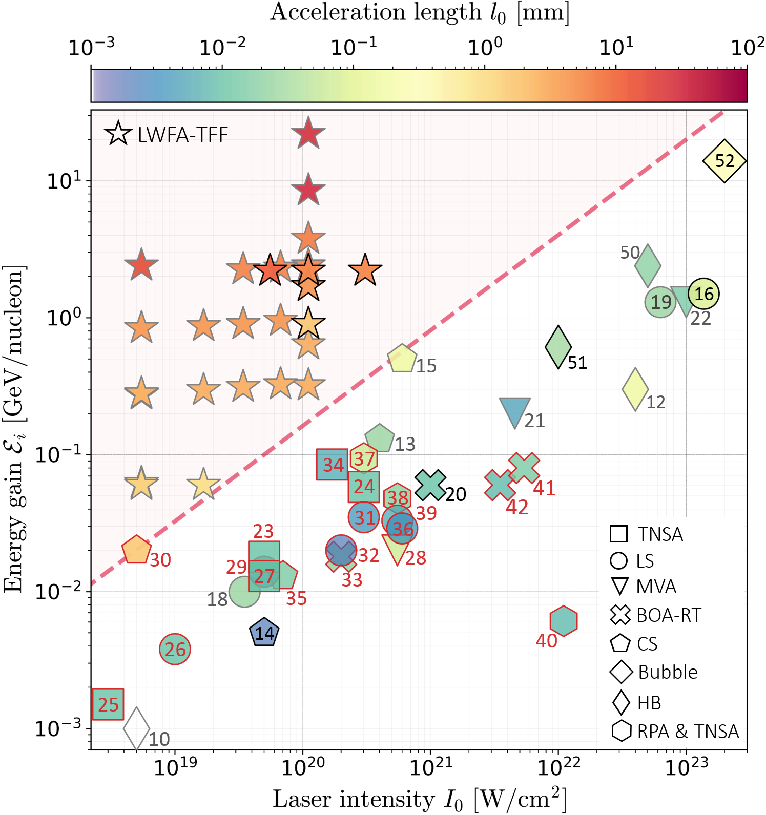
In this article, we describe how the generalization of the flying focus to include motion of the focal spot perpendicular to the direction of laser propagation enables the wakefield acceleration of ions. Laser wakefield acceleration via a transverse flying focus (LWFA-TFF) exploits the strong electrostatic fields that are formed by transverse electron expulsion from a high intensity laser focal spot. This new type of laser-ion accelerator combines the advantages of laser wakefield acceleration with a novel approach for the spatiotemporal control of laser intensity. As shown by the comparison between LWFA-TFF and existing laser-plasma ion-acceleration approaches in Fig. 1, this mechanism uses moderate laser intensities ( W/cm2) and extended acceleration distances (mm-cm) to accelerate ions to up to GeV energies, far surpassing what other approaches can achieve with similar laser intensity.
II Results
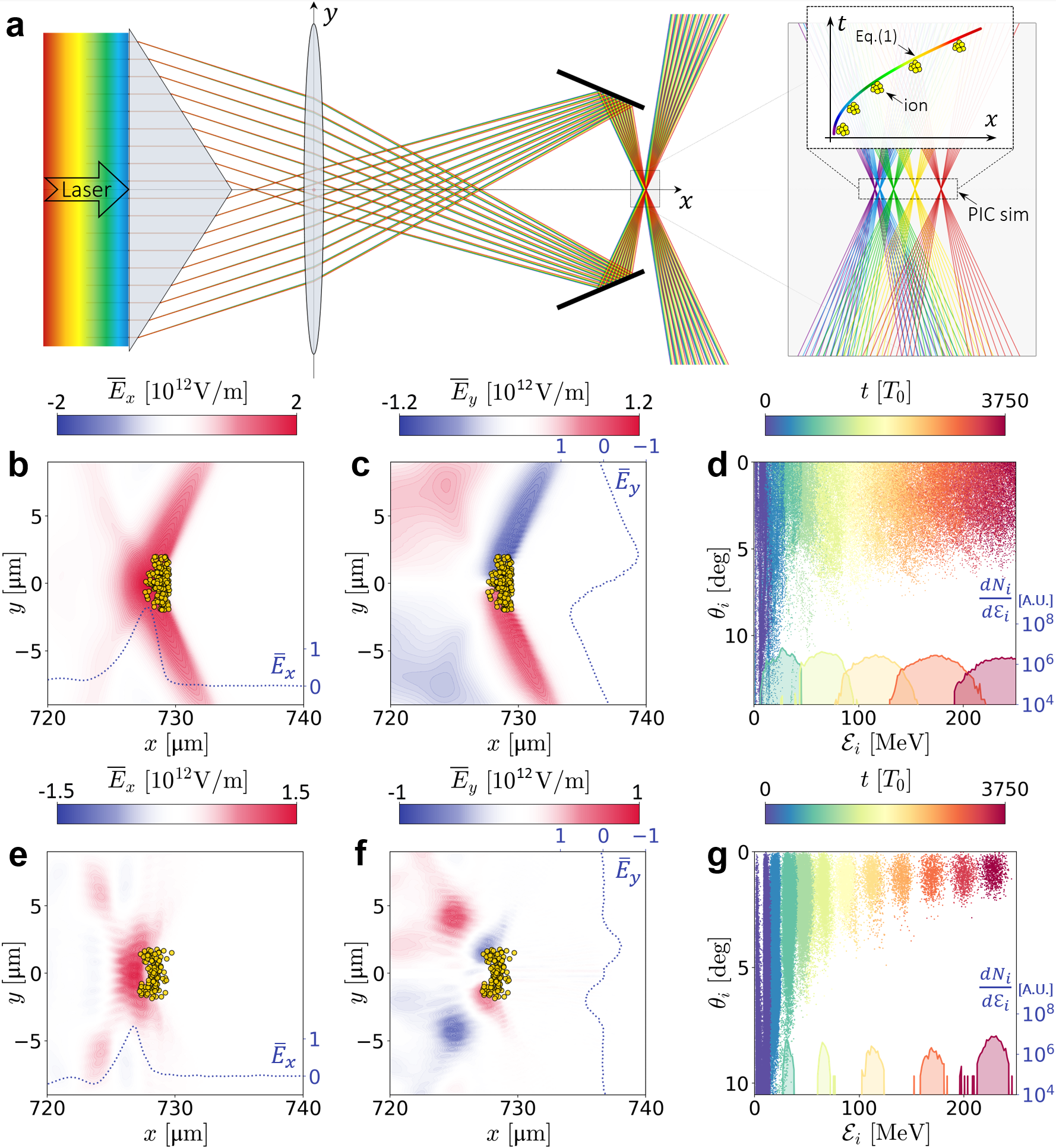
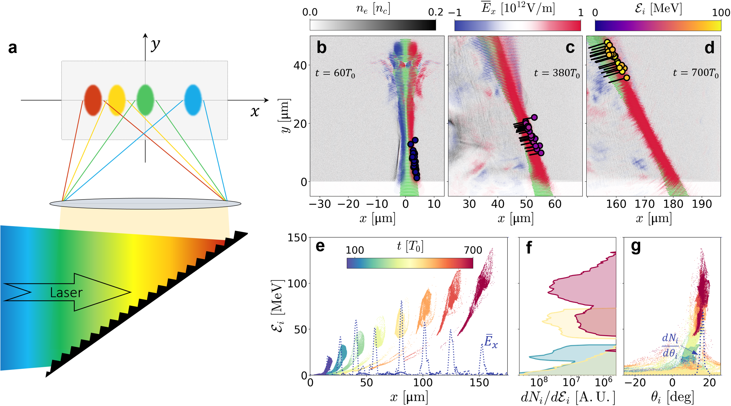
Consider the focal spot of a laser pulse whose envelope has a velocity perpendicular to the laser propagation direction, as might be created, for example, by a chirped pulse passing though a grating followed by a lens. Unlike a stationary focal spot in an underdense plasma, where the strong transverse electrostatic field created by the ponderomotive expulsion of electrons accelerates ions to approximately 10 MeV over microns [65], a moving focal spot can keep ions within the accelerating gradient over an extended distance. An axisymmetric system with transverse focal spot motion can be constructed from a combination of axicon and dispersive optics: e.g., an axicon lens, spherical lens, and axicon mirror as drawn in Fig. 2a. The axicon and spherical lens alone would produce a ring focus, with the chromatic dispersion of these two optics creating rings of slightly different radii for each color. When combined with an axicon mirror, the ring foci can be made to collapse onto the axis. Then, if the lens and mirror parameters are chosen appropriately, each color can be made to focus at a desired location along the -axis. This chromatic approach is easiest to visualize, but similar focusing geometries can be implemented with flying focus configurations employing echelons or optics with time-dependent refractive indices. The simulations presented here used boundary conditions based on the latter technique (see Methods). This focusing geometry produces strong (TeV/m) electrostatic accelerating fields in the x-direction and ion-focusing fields in the y-direction, as shown by two-dimensional (2D) particle-in-cell (PIC) simulations in Fig. 2bcd and three-dimensional (3D) PIC simulations in Fig. 2efg. If the focus and resulting field move along an appropriate trajectory, ions can be indefinitely subjected to TeV/m acceleration, allowing for energy accumulation limited only by the energy of the laser pulse.
For efficient ion energy gain, the location of the maximum of the accelerating field () as a function of time () should match the trajectory of an ion accelerated by a constant force to relativistic velocity:
| (1) |
where is the apparent acceleration of the location of the field maximum and is the speed of light. The ions will accelerate based on their mass (), charge (), and the field strength (), so matching the acceleration of the field to the trajectory of the ions requires . As shown by the PIC results in Fig. 2dg, an ion bunch can be readily accelerated to more than 200 MeV if the focus follows the time-dependent trajectory given by Eq. 1 (see Fig. 2a). In these simulations, the laser reached a peak intensity of W/cm2 in a hydrogen plasma with , where , is the electron mass, C is the elementary charge, and is the laser frequency. The acceleration of the focus was where fs is the laser period [see Methods for detailed parameters]. In both 2D and 3D simulations, this produced a stable moving field (Fig. 2b,e) and corresponding transverse field that suppressed the protons’ transverse dispersion (Fig. 2c,f). The proton distributions in energy-angle space shown in Fig. 2dg demonstrate that the acceleration process yielded a monoenergetic proton beam with peak energy MeV, where is the ion kinetic energy, is the relativistic Lorentz factor, and is the ion divergence half-angle. The ions were accelerated over 1 mm, resulting in energy gains that are almost two orders of magnitude larger than proton energies achievable in a static transverse field.
The 2D simulations reproduced the key features of the 3D simulations, including the peak energy and field structure, which confirms the reliability of 2D simulations for parametric studies. The energy spread and angular divergence were both narrower in 3D, indicating that 2D simulations will tend to underestimate collimation and monochromaticity. The generated proton beam in the 2D simulation had a full-width-at-half-maximum (FWHM) energy spread and a FWHM angular spread . In contrast, in the 3D simulation, the proton beam was collimated with an energy spread and an angular spread after an acceleration distance of cm (Fig. 2g).
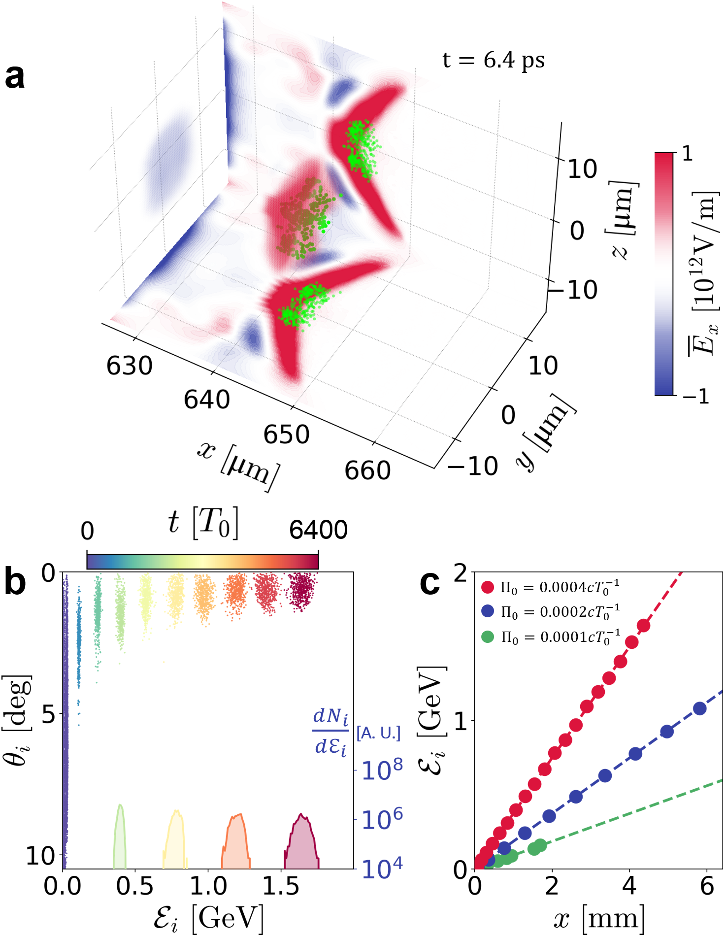
Over longer acceleration distances, this mechanism allows ion acceleration to GeV energies. Using the flying focus geometry illustrated in Fig. 2a, a laser with total energy kJ and duration ps focused in a hydrogen plasma with electron density cm-3 produced the fields shown in Fig. 3a. The laser power was TW and the peak intensity at the focal position was , comparable to the capabilities of contemporary large-scale laser facilities. The focal position of the pulse satisfied the synchronized acceleration condition . After accelerating for and propagating a distance of mm, the protons attained the angular-energy distribution shown in Fig. 3b. The proton beam was collimated along the longitudinal direction with divergence angle and exhibited a quasi-monoenergetic spectrum peaked at GeV with relative energy spread. The total charge of the proton beam was pC. The correlation between the proton energy and the acceleration distance for different values of in Fig. 3c demonstrates that the protons were synchronously accelerated by the charge-separation field produced by the flying-focus laser pulse.
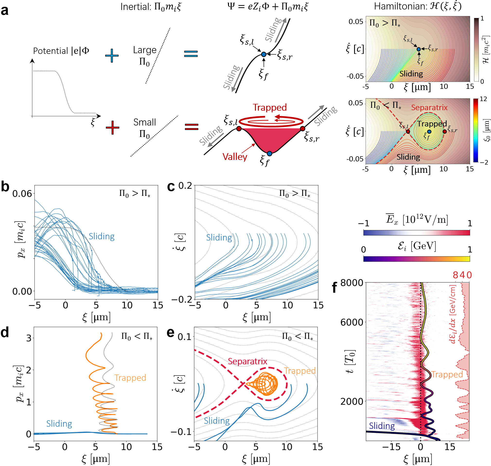
To explain and generalize these results, an analytic theory was developed to describe the acceleration process based on a conserved Hamiltonian that characterizes the ion dynamics in the co-moving frame of the flying focus. Ions can be efficiently accelerated to relativistic energy if they are trapped inside the separatrix of the Hamiltonian in space (Fig. 4a), where is the coordinate in the co-moving frame and the overdot denotes a time derivative [see Methods]. From this Hamiltonian, the criterion for ion trapping is , which sets a relationship between the acceleration and the maximum strength of the accelerating electric field . The trapping criterion corresponds to the appearance of a local minimum in the profile of the ion’s total potential energy (Fig. 4a), which is the sum of the electric energy and the inertial energy resulting from the co-moving frame . The upper and lower panels of Fig. 4a show relatively large and small inertial potentials, respectively. A potential valley appears for the total potential that satisfies the trapping criterion; ions within this valley oscillate longitudinally in , which is equivalent to rotating within the separatrix. The left and right boundaries of the potential valley ( and ) have equivalent points on the separatrix at . The local minimum potential at , where the electric field and the fictitious inertial force are balanced, corresponds to the fixed point in phase space where the ion is static in the comoving frame. The separatrix divides phase space into trapping and sliding regimes. The ions initialized with at are trapped and efficiently accelerated while the ones with or slide away from the electric field. For increased , the potential valley shrinks. At the critical condition where , the separatrix vanishes and no ions can be accelerated by the flying focus.
Particle trajectories found in 2D PIC simulations match this Hamiltonian analysis, as shown in Fig. 4b-e, where Fig. 4bc and Fig. 4de correspond to and , respectively. Here the threshold for separatrix disappearance is , so only sliding proton dynamics exist in the case of higher acceleration. Protons were trapped and accelerated in the lower acceleration case, as shown by the momentum accumulation (Fig. 4d) and the separatrix in phase space (Fig. 4e). Figure 4f shows the time evolution of a trapped proton trajectory in the co-moving frame. The average acceleration gradient GeV/cm agrees well with the acceleration provided by the drifting electric field GeV/cm. Microscopically, the proton undergoes multiple cycles of nonuniform acceleration within the field, corresponding to oscillations in the separatrix shown in Fig. 4e.
An explicit formula for the trapping criterion can be found by calculating the self-generated electrostatic field at the laser-driven plasma channel edge. The field was estimated by balancing the average ponderomotive force of the laser pulse in the -direction , calculated as , with the electrostatic force exerted on plasma electrons. Here is the normalized vector potential and is the laser focal spot size. Utilizing , the electric field is . Given the relation of obtained from fitting of simulation results, the electric field can be written as . Then, the threshold for ion trapping by the accelerating field is:
| (2) |
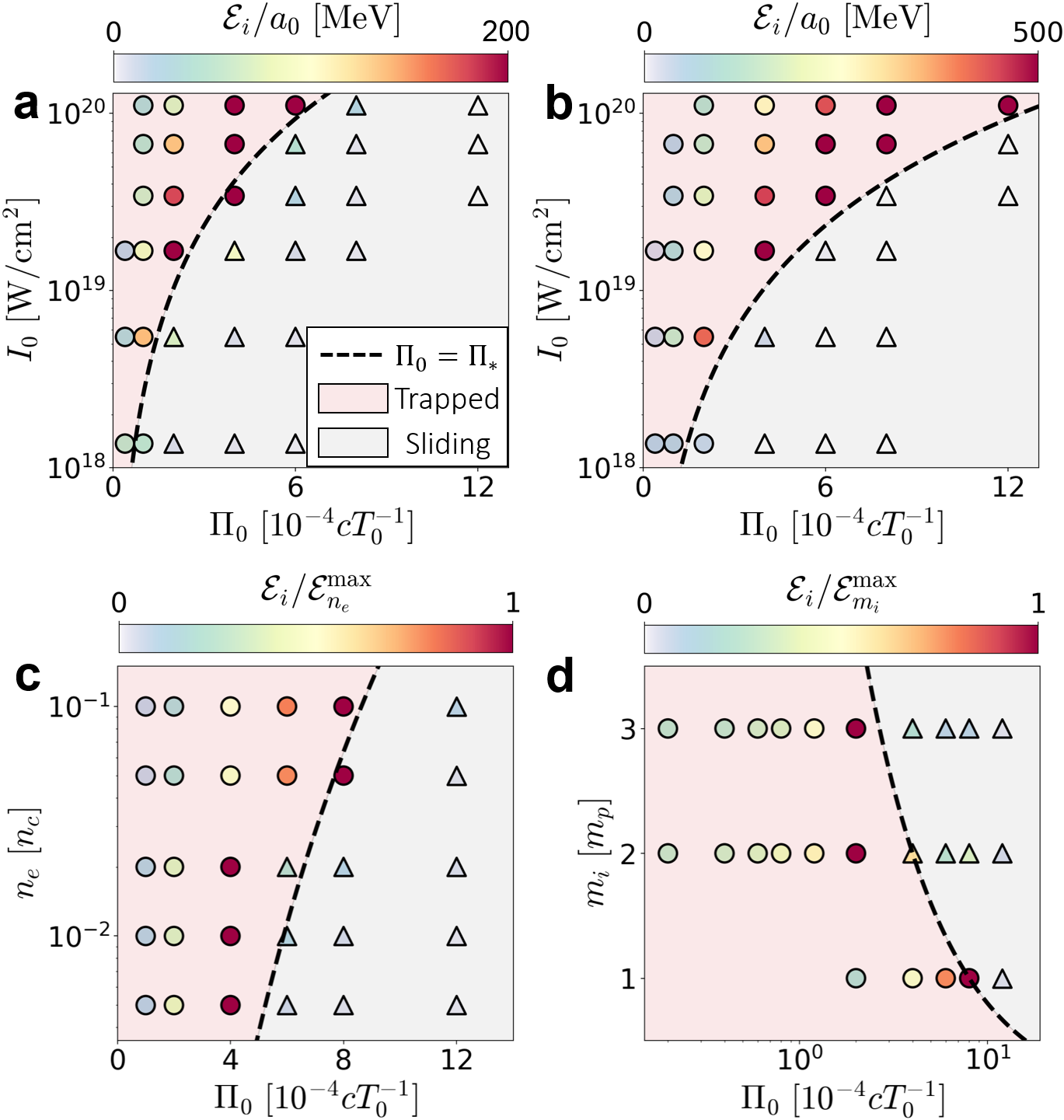
This trapping threshold () was validated with 2D PIC simulations across different laser intensities, focal spot sizes (), plasma electron densities (), and accelerations . The analytic threshold shown in Fig. 5 (dashed lines) agrees well with the simulations whether the ions are trapped and accelerated (circles) or slip without acceleration (triangles). In Fig. 5ab, the threshold increases with rising laser intensity because the plasma self-generated electric field is proportional to . Results for m (Fig. 5a) and m (Fig. 5b) show that the larger spot size produces a smaller threshold because the accelerating field is inversely proportional to . As the accelerating field is positively related to the plasma electron density , the trapping threshold rises with increasing (Fig. 5c). Heavier ions are more difficult to accelerate, resulting in a smaller trapping threshold for larger ion masses (Fig. 5d). As shown in each of these subfigures, accelerations close to, but below, the threshold produce the highest ion energies.
If the desired ion energies are on the order of 200 MeV, the axisymmetric geometry can be replaced by a simpler focusing geometry based on a chirped laser pulse traveling through a grating and then a lens (Fig. 6a). In Fig. 6, the focal spot moves in the direction according to Eq. 1 with , over a distance of 160m, producing a proton beam with an average energy of MeV. Figure 6bcd shows the motion of the ions (circles) with respect to the position of the electrostatic field, and Fig. 6e plots the evolution of sampled proton energies in position-energy space with respect to the co-moving accelerating field . The proton energy spectra in Fig. 6(f) shows a quasi-monoenergetic proton beam with a peak energy of MeV and a FWHM relative spread of at ps.
In this configuration, the total energy that can be accumulated with even an ideal driver is limited by the finite transit time of light across the focal region. As the velocity of the focal spot becomes comparable to , the accelerating field tilts with respect to the -axis (Fig. 6d). From the beam geometry, the tilt angle can be calculated as . As shown in Fig. 6g, the resulting -component of the accelerating field leads to a deflection of the accelerated protons () in agreement with the analytic prediction , where is the averaged transverse velocity. At this energy, the ion beam is still collimated (FWHM divergence angle ), and the average acceleration direction is simply displaced from the -axis. Moderate improvements to the maximum energy could be made by moving the focal spot in the ion propagation direction rather than purely transversely, but continued acceleration is disrupted by the motion of the ions away from the focus in the -direction, eventually causing them to leave the region of substantial electrostatic field. The ion trapping threshold of Eq. 2 is also valid for predicting the regimes of this asymmetric ion acceleration, which is confirmed by the PIC simulations of parameter scans in the Supplemental Material. Although further acceleration requires a more axisymmetric driver geometry, this simplified scheme offers an alternative for moderate energy ( MeV) ion acceleration.
III Discussion
The application of a transverse flying focus to ion acceleration offers a potential path towards 100 MeV quasi-monoenergetic ions from laser-driven sources. Accelerating ions in an underdense plasma removes several limitations of TNSA and other ion-acceleration mechanisms that require overdense targets, including deformation due to the laser prepulse [44], difficulty accelerating heavy ions in the presence of protons [40, 43], and complex and low-repetition rate targetry [37, 38, 42]. The use of lower laser intensities and plasma densities may also mitigate kinetic instabilities [66, 67], avoid laser energy dissipation at ultrarelativistic intensities [68, 69], and relax requirements on the laser facility. In contrast to existing mechanisms, where experimental results remain at the 100 MeV/nucleon level and simulations have found that laser intensities greater than are required for GeV proton beams, the scheme proposed here combines a GeV/cm gradient and centimeter-scale acceleration distances with laser intensities less than to reach GeV/nucleon ion energies with a picosecond-duration laser pulse. Like wakefield acceleration of electrons, LWFA-TFF produces quasi-monoenergetic, collimated, and high-energy particle beams. Furthermore, the lack of complex solid-density targets make the mechanism more suitable for high-repetition-rate operation, which is a requirement for high-dose applications. The ion energy, ion energy spread, and beam divergence are comparable to those required for applications of energetic ion beams. For example, ion energies in the 0.1 to 1 GeV/nucleon range are important for medical applications and relativistic energies—the upper end of this range—would be necessary for seeding a traditional wakefield accelerator with ions.
The transverse flying focus that we introduce and its implementation in a ring focusing geometry offer new ways to control and apply high-strength electromagnetic fields that may have applications beyond ion acceleration. In particular, the complete decoupling of focal spot motion from the direction of light propagation may also allow improvements to electron acceleration, photon acceleration, or terahertz radiation generation. Here, it enables the efficient and stable acceleration generation of monoenergetic ion beams in the critical 0.1 - 1 GeV/nucleon energy range with laser parameters that are accessible today, while avoiding complex targets, exquisitely tuned plasma parameters, and extreme intensities, creating a potential new route to the widespread application of compact laser-based ion sources.
IV Methods
Particle-in-Cell Simulations: The relativistic PIC code EPOCH [70] was used to conduct two and three dimensional simulations of the ion acceleration mechanism. Two distinct simulation geometries were considered: (1) a laser pulse focused through an axicon lens, spherical lens, and axicon mirror, providing a transversely moving ring focus (Fig. 2), and (2) a laser pulse focused through a transversely chromatic lens, resulting in transverse motion of the focal spot (Fig. 6). Key parameters for the simulations are outlined below; complete details are available in the Supplemental Material.
For two-dimensional simulations of configuration (1), presented in Figs. 2bcd, 4 and 5, the 2D domain () was discretized with , where m is the laser wavelength. All PIC simulations used a computational time step . The simulation used a moving window following the pulse and accelerated ions. The ring-focused laser pulse was approximated in 2D as two laser pulses incident from the upper and lower boundaries at with respect to the -axis. The two laser pulses were focused to m ( radius) with peak normalized field amplitude , corresponding to a peak intensity of W/cm2. To realize a flying focus, the transverse profiles of the pulses at the boundary were set by , where , is the Rayleigh range, and is the distance from the boundary to the focal position. The pulses had a trapezoidal temporal profile with duration of 26.6 ps and 520 fs linear up and down ramps. The laser focal spot position moved with and with and . This laser setup is equivalent to the schematic shown in Fig. 2(a) using a time-dependent refractive index rather than chromatic dispersion to focus different temporal components of the pulse to the specified longitudinal positions. As in the configuration above, a fully ionized hydrogen plasma with and 50 particles per cell of each species were used. The density was uniform for m, with linear gradients at m m.
For configuration (2), presented in Fig. 6, the 2D moving-window simulation domain was with grid resolution . In the presented simulation, the laser had a spot size m, peak intensity W/cm2, and propagated from the lower boundary along the positive -axis. The transverse profile of the pulse was set to , with at the boundary. The pulse had a trapezoidal temporal profile with duration 2.33 ps and 46 fs linear up and down ramps. The apparent acceleration was set to . A uniform hydrogen plasma with electron number density was created for . 50 macroparticles per cell were used for both the electrons and ions.
The three-dimensional simulations (Fig. 2efg, 3) had a computational domain with spatial resolution . The simulation used a moving window following the the flying focus position. The laser pulse had a symmetric intensity distribution incident from the lateral boundaries, where the local phase, intensity, and polarization were found from a calculation of pulse propagation through the drawn optical system (see Supplemental Material). The flying-focus was implemented by changing the focal spot wavelength and position in time based on the desired acceleration profile. The average laser propagation direction with respect to the axis was . The pulses had a trapezoidal temporal profile with duration 21.1 ps and 420 fs ramps, and produced a focus with m and peak intensity W/cm2. The focal position was set at and with . The hydrogen plasma was uniform with over m. 5 macroparticles per cell were used for both the electrons and ions.
In all PIC simulations, the electrostatic fields and were calculated by averaging the instantaneous electric fields ( and ) over two laser periods.
Hamiltonian Analysis: In the one-dimensional approximation, an ion comoving with a translating electric field is described by:
| (3) | |||
| (4) | |||
| (5) |
where the tilde denotes values for an ion that is ‘static’ with respect to the drifting field, meaning that the drifting field has the same trajectory as the ion; in other words, and . The acceleration of the drifting electric field is . The ion dynamics relative to the static ion evolve according to
| (6) | |||
| (7) |
where is the relative coordinate and is used. Utilizing the electric potential , one can find the conserved Hamiltonian
| (8) |
where is assumed to change slowly. The criterion for the ion being trapped by the drifting electric field is that has two solutions [see and in Fig. 4(a)], which is equivalent to , i.e.,
| (9) |
If the electric field exerted on the ion is approximated as , which is in agreement with PIC simulations, the time derivative of can be formulated as
| (10) |
Assuming that the variation of is slow, the ion motion is given by:
| (11) |
where is determined by the initial condition . The oscillation frequency within the potential valley indicates the ion oscillation in phase space becomes slower with increasing energy, which is confirmed by the particle tracking result of PIC simulations shown in Fig. 4(f).
V Data availability
The data supporting the findings of this study are available from the corresponding authors upon reasonable request.
Acknowledgements.
VI Acknowledgments
This work was partially supported by NSF Grant PHY-2308641. The work of JPP is supported by the Office of Fusion Energy Sciences under Award Number DE-SC00215057, the Department of Energy National Nuclear Security Administration under Award Number DE-NA0003856, the University of Rochester, and the New York State Energy Research and Development Authority. The PIC code EPOCH is funded by the UK EPSRC grants EP/G054950/1, EP/G056803/1, EP/G055165/1 and EP/ M022463/1. This work used Delta-cpu at National Center for Supercomputing Applications (NCSA) through allocation PHY230120 and PHY230121 from the Advanced Cyberinfrastructure Coordination Ecosystem: Services & Support (ACCESS) program, which is supported by National Science Foundation grants #2138259, #2138286, #2138307, #2137603, and #2138296. Some of the computing for this project was performed on the (Stanford) Sherlock cluster. We would like to thank Stanford University and the Stanford Research Computing Center for providing computational resources and support that contributed to these research results.
VII Author contributions
M.R.E. conceived the idea and supervised the project. Z.G. developed the theoretical model and conducted and analyzed the simulations. S.C., M.R.E. and J.P.P. designed the optical configuration of the transverse flying focus. All authors discussed and assessed the results. The article was written by Z.G. and M.R.E. with contributions from all authors.
VIII Competing interests
The authors declare no competing interests.
References
- [1] Tumasyan, A. et al. Search for exotic Higgs boson decays with events containing two merged diphotons in proton-proton collisions at . Phys. Rev. Lett. 131, 101801 (2023).
- [2] Kondo, Y. et al. First observation of 28O. Nature 620, 965–970 (2023).
- [3] Marcowith, A. et al. The microphysics of collisionless shock waves. Rep. Prog. Phys. 79, 046901 (2016).
- [4] Schaeffer, D. B. et al. Proton imaging of high-energy-density laboratory plasmas. Rev. Mod. Phys. 95, 045007 (2023).
- [5] Schardt, D., Elsässer, T. & Schulz-Ertner, D. Heavy-ion tumor therapy: Physical and radiobiological benefits. Rev. Mod. Phys. 82, 383 (2010).
- [6] Wiedemann, H. Particle accelerator physics (Springer Nature, 2015).
- [7] Daido, H., Nishiuchi, M. & Pirozhkov, A. S. Review of laser-driven ion sources and their applications. Rep. Prog. Phys. 75, 056401 (2012).
- [8] Macchi, A., Borghesi, M. & Passoni, M. Ion acceleration by superintense laser-plasma interaction. Rev. Mod. Phys. 85, 751 (2013).
- [9] Mora, P. Plasma expansion into a vacuum. Phys. Rev. Lett. 90, 185002 (2003).
- [10] Macchi, A., Cattani, F., Liseykina, T. V. & Cornolti, F. Laser acceleration of ion bunches at the front surface of overdense plasmas. Phys. Rev. Lett. 94, 165003 (2005).
- [11] Robinson, A. et al. Relativistically correct hole-boring and ion acceleration by circularly polarized laser pulses. Plasma Phys. Control. Fusion 51, 024004 (2009).
- [12] Naumova, N. et al. Hole boring in a DT pellet and fast-ion ignition with ultraintense laser pulses. Phys. Rev. Lett. 102, 025002 (2009).
- [13] Silva, L. O. et al. Proton shock acceleration in laser-plasma interactions. Phys. Rev. Lett. 92, 015002 (2004).
- [14] Ji, L. et al. Generating monoenergetic heavy-ion bunches with laser-induced electrostatic shocks. Phys. Rev. Lett. 101, 164802 (2008).
- [15] Fiúza, F. et al. Laser-driven shock acceleration of monoenergetic ion beams. Phys. Rev. Lett. 109, 215001 (2012).
- [16] Esirkepov, T., Borghesi, M., Bulanov, S., Mourou, G. & Tajima, T. Highly efficient relativistic-ion generation in the laser-piston regime. Phys. Rev. Lett. 92, 175003 (2004).
- [17] Klimo, O., Psikal, J., Limpouch, J. & Tikhonchuk, V. Monoenergetic ion beams from ultrathin foils irradiated by ultrahigh-contrast circularly polarized laser pulses. Phys. Rev. Accel. Beams. 11, 031301 (2008).
- [18] Yan, X. et al. Generating high-current monoenergetic proton beams by a circularly polarized laser pulse in the phase-stable acceleration regime. Phys. Rev. Lett. 100, 135003 (2008).
- [19] Qiao, B., Zepf, M., Borghesi, M. & Geissler, M. Stable GeV ion-beam acceleration from thin foils by circularly polarized laser pulses. Phys. Rev. Lett. 102, 145002 (2009).
- [20] Yin, L. et al. Three-dimensional dynamics of breakout afterburner ion acceleration using high-contrast short-pulse laser and nanoscale targets. Phys. Rev. Lett. 107, 045003 (2011).
- [21] Nakamura, T., Bulanov, S. V., Esirkepov, T. Z. & Kando, M. High-energy ions from near-critical density plasmas via magnetic vortex acceleration. Phys. Rev. Lett. 105, 135002 (2010).
- [22] Bulanov, S. S. et al. Generation of GeV protons from 1 PW laser interaction with near critical density targets. Phys. Plasmas 17, 043105 (2010).
- [23] Clark, E. et al. Measurements of energetic proton transport through magnetized plasma from intense laser interactions with solids. Phys. Rev. Lett. 84, 670 (2000).
- [24] Snavely, R. et al. Intense high-energy proton beams from petawatt-laser irradiation of solids. Phys. Rev. Lett. 85, 2945 (2000).
- [25] Maksimchuk, A., Gu, S., Flippo, K., Umstadter, D. & Bychenkov, V. Y. Forward ion acceleration in thin films driven by a high-intensity laser. Phys. Rev. Lett. 84, 4108 (2000).
- [26] Hegelich, B. M. et al. Laser acceleration of quasi-monoenergetic MeV ion beams. Nature 439, 441–444 (2006).
- [27] Toncian, T. et al. Ultrafast laser-driven microlens to focus and energy-select mega-electron volt protons. Science 312, 410–413 (2006).
- [28] Willingale, L. et al. Collimated multi-MeV ion beams from high-intensity laser interactions with underdense plasma. Phys. Rev. Lett. 96, 245002 (2006).
- [29] Henig, A. et al. Radiation-pressure acceleration of ion beams driven by circularly polarized laser pulses. Phys. Rev. Lett. 103, 245003 (2009).
- [30] Haberberger, D. et al. Collisionless shocks in laser-produced plasma generate monoenergetic high-energy proton beams. Nat. Phys 8, 95–99 (2012).
- [31] Kar, S. et al. Ion acceleration in multispecies targets driven by intense laser radiation pressure. Phys. Rev. Lett. 109, 185006 (2012).
- [32] Bin, J. et al. Ion acceleration using relativistic pulse shaping in near-critical-density plasmas. Phys. Rev. Lett. 115, 064801 (2015).
- [33] Palaniyappan, S. et al. Efficient quasi-monoenergetic ion beams from laser-driven relativistic plasmas. Nat. Commun. 6, 1–12 (2015).
- [34] Wagner, F. et al. Maximum proton energy above 85 MeV from the relativistic interaction of laser pulses with micrometer thick targets. Phys. Rev. Lett. 116, 205002 (2016).
- [35] Zhang, H. et al. Collisionless shock acceleration of high-flux quasimonoenergetic proton beams driven by circularly polarized laser pulses. Phys. Rev. Lett. 119, 164801 (2017).
- [36] Scullion, C. et al. Polarization dependence of bulk ion acceleration from ultrathin foils irradiated by high-intensity ultrashort laser pulses. Phys. Rev. Lett. 119, 054801 (2017).
- [37] Higginson, A. et al. Near-100 MeV protons via a laser-driven transparency-enhanced hybrid acceleration scheme. Nat. Commun. 9, 1–9 (2018).
- [38] Ma, W. et al. Laser acceleration of highly energetic carbon ions using a double-layer target composed of slightly underdense plasma and ultrathin foil. Phys. Rev. Lett. 122, 014803 (2019).
- [39] McIlvenny, A. et al. Selective ion acceleration by intense radiation pressure. Phys. Rev. Lett. 127, 194801 (2021).
- [40] Wang, P. et al. Super-heavy ions acceleration driven by ultrashort laser pulses at ultrahigh intensity. Phys. Rev. X. 11, 021049 (2021).
- [41] Rehwald, M. et al. Ultra-short pulse laser acceleration of protons to 80 MeV from cryogenic hydrogen jets tailored to near-critical density. Nat. Commun. 14, 4009 (2023).
- [42] Dover, N. P. et al. Enhanced ion acceleration from transparency-driven foils demonstrated at two ultraintense laser facilities. Light Sci. Appl. 12, 71 (2023).
- [43] Martin, P. et al. Narrow-band acceleration of gold ions to GeV energies from ultra-thin foils. Commun. Phys. 7, 3 (2024).
- [44] Kaluza, M. et al. Influence of the laser prepulse on proton acceleration in thin-foil experiments. Phys. Rev. Lett. 93, 045003 (2004).
- [45] Tajima, T. & Dawson, J. M. Laser electron accelerator. Phys. Rev. Lett. 43, 267 (1979).
- [46] Esarey, E., Schroeder, C. & Leemans, W. Physics of laser-driven plasma-based electron accelerators. Rev. Mod. Phys. 81, 1229 (2009).
- [47] Gonsalves, A. et al. Petawatt laser guiding and electron beam acceleration to 8 GeV in a laser-heated capillary discharge waveguide. Phys. Rev. Lett. 122, 084801 (2019).
- [48] Wang, W. et al. Free-electron lasing at 27 nanometres based on a laser wakefield accelerator. Nature 595, 516–520 (2021).
- [49] Salamin, Y. I., Harman, Z. & Keitel, C. H. Direct high-power laser acceleration of ions for medical applications. Phys. Rev. Lett. 100, 155004 (2008).
- [50] Liu, B., Shi, M., Zepf, M., Lei, B. & Seipt, D. Accelerating ions by crossing two ultraintense lasers in a near-critical relativistically transparent plasma. Phys. Rev. Lett. 129, 274801 (2022).
- [51] Brantov, A., Govras, E., Kovalev, V. & Bychenkov, V. Y. Synchronized ion acceleration by ultraintense slow light. Phys. Rev. Lett. 116, 085004 (2016).
- [52] Shen, B., Li, Y., Yu, M. & Cary, J. Bubble regime for ion acceleration in a laser-driven plasma. Phys. Rev. E 76, 055402 (2007).
- [53] Sainte-Marie, A., Gobert, O. & Quere, F. Controlling the velocity of ultrashort light pulses in vacuum through spatio-temporal couplings. Optica 4, 1298–1304 (2017).
- [54] Froula, D. H. et al. Spatiotemporal control of laser intensity. Nat. Photonics 12, 262–265 (2018).
- [55] Liberman, A. et al. Use of spatiotemporal couplings and an axiparabola to control the velocity of peak intensity. Opt. Lett. 49, 814–817 (2024).
- [56] Pigeon, J. et al. Ultrabroadband flying-focus using an axiparabola-echelon pair. Opt. Express 32, 576–585 (2024).
- [57] Simpson, T. T. et al. Spatiotemporal control of laser intensity through cross-phase modulation. Opt. Express 30, 9878–9891 (2022).
- [58] Turnbull, D. et al. Raman amplification with a flying focus. Phys. Rev. Lett. 120, 024801 (2018).
- [59] Howard, A. et al. Photon acceleration in a flying focus. Phys. Rev. Lett. 123, 124801 (2019).
- [60] Palastro, J. et al. Dephasingless laser wakefield acceleration. Phys. Rev. Lett. 124, 134802 (2020).
- [61] Caizergues, C., Smartsev, S., Malka, V. & Thaury, C. Phase-locked laser-wakefield electron acceleration. Nat. Photonics 14, 475–479 (2020).
- [62] Kabacinski, A. et al. Spatio-temporal couplings for controlling group velocity in longitudinally pumped seeded soft X-ray lasers. Nat. Photonics 17, 354–359 (2023).
- [63] Formanek, M., Palastro, J. P., Ramsey, D., Weber, S. & Di Piazza, A. Signatures of vacuum birefringence in low-power flying focus pulses. Phys. Rev. D 109, 056009 (2024).
- [64] Ramsey, D. et al. Exact solutions for the electromagnetic fields of a flying focus. Phys. Rev. A 107, 013513 (2023).
- [65] Macchi, A., Ceccherini, F., Cornolti, F., Kar, S. & Borghesi, M. Electric field dynamics and ion acceleration in the self-channeling of a superintense laser pulse. Plasma Phys. Control. Fusion 51, 024005 (2009).
- [66] Palmer, C. et al. Rayleigh-Taylor instability of an ultrathin foil accelerated by the radiation pressure of an intense laser. Phys. Rev. Lett. 108, 225002 (2012).
- [67] Wan, Y., Andriyash, I., Lu, W., Mori, W. & Malka, V. Effects of the transverse instability and wave breaking on the laser-driven thin foil acceleration. Phys. Rev. Lett. 125, 104801 (2020).
- [68] Di Piazza, A., Müller, C., Hatsagortsyan, K. & Keitel, C. Extremely high-intensity laser interactions with fundamental quantum systems. Rev. Mod. Phys. 84, 1177 (2012).
- [69] Gonoskov, A., Blackburn, T., Marklund, M. & Bulanov, S. Charged particle motion and radiation in strong electromagnetic fields. Rev. Mod. Phys. 94, 045001 (2022).
- [70] Arber, T. et al. Contemporary particle-in-cell approach to laser-plasma modelling. Plasma Phys. Control. Fusion 57, 113001 (2015).