Multi-Layer Network Formation through HAPS Base Station and Transmissive RIS-Equipped UAV
Abstract
In order to bolster future wireless networks, there has been a great deal of interest in non-terrestrial networks, especially aerial platform stations including the high altitude platform station (HAPS) and uncrewed aerial vehicles (UAV). These platforms can integrate advanced technologies such as reconfigurable intelligent surfaces (RIS) and non-orthogonal multiple access (NOMA). In this regard, this paper proposes a multi-layer network architecture to improve the performance of conventional HAPS super-macro base station (HAPS-SMBS)-assisted UAV. The architecture includes a HAPS-SMBS, UAVs equipped with active transmissive RIS, and ground Internet of things devices. We also consider multiple-input single-output (MISO) technology, by employing multiple antennas at the HAPS-SMBS and a single antenna at the Internet of things devices. Additionally, we consider NOMA as the multiple access technology as well as the existence of hardware impairments as a practical limitation. In particular, we compare the proposed system model with three different scenarios: HAPS-SMBS-assisted UAV that are equipped with active transmissive RIS and supported by single-input single-output system, HAPS-SMBS-assisted UAV that are equipped with amplify-and-forward relaying, and HAPS-SMBS-assisted UAV-equipped with passive transmissive RIS. Sum rate and energy efficiency are used as performance metrics, and the findings demonstrate that, in comparison to all benchmarks, the proposed system yields higher performance gain. Moreover, the hardware impairment limits the system performance at high transmit power levels.
Index Terms:
HAPS, non-terrestrial networks, hardware impairment, MISO, NOMA, and transmissive RIS.I Introduction
The sixth-generation (6G) technology standard for cellular networks entails significant changes in network structures and technologies. In this regard, non-terrestrial networks (NTN) integrated with 6G networks offer a cost-effective approach to establishing seamless and expansive wireless connectivity across diverse environments—including rural, remote, and urban areas [1]. According to the Third Generation Partnership Project (3GPP), NTN includes three main kinds of flying objects, namely satellites, high altitude platform stations (HAPS), and uncrewed aerial vehicles (UAV) [2]. NTN can act as an extension to the current ground network, increasing its capacity and extending coverage, which is consistent with the usage scenarios and capabilities described by the International Telecommunication Union (ITU) vision document for International Mobile Telecommunications (IMT)-2030 [3].
As another promising technology, smart radio environments, named reconfigurable intelligent surfaces (RIS), have recently been proposed for intelligently controlling wireless channels to achieve improved communication performance [4]. In particular, a RIS array is composed of many passive elements that aggregate reflect electromagnetic waves in the preferred manner to change the way that signals propagate in a wireless environment. RIS can be mounted on aerial platforms as a reflective layer between ground base stations and ground devices [1]. In the absence of direct links, the joint optimization of trajectory and phase shift for a HAPS base station with RIS-equipped UAV (UAV-RIS) for a multiple-input single-output (MISO) system was investigated in [5]. The authors in [6] obtained the outage probability, average transmission rate, and spectral efficiency for a satellite-assisted HAPS with UAV-RIS, when both act as relays. Moreover, non-orthogonal multiple access (NOMA) was presented as a promising technology, which can serve multiple users on the same resource block [7, 8]. On the other hand, the active RIS with NOMA and hardware impairments (HWI) were considered to maximize the sum rate in the absence of aerial platforms in [9, 10].
Most previous works as in [5] take into account two dimensions (2D) for reflective RIS, meaning that 2D reflective RIS will be directed in one direction to serve users at the expense of others. Therefore, it is unlikely that all the ground users have full coverage. Moreover, they consider a passive RIS technology in their investigation. Nevertheless, there are some disadvantages associated with the passive RIS. For example, the received signal experiences product/double path-loss attenuation (i.e., the transmitter to RIS and RIS to receiver paths) in the absence of signal amplification, causing it to become dramatically low, thereby the potential of RIS is significantly restricted by this “double path-loss” attenuation. In this regard, the active RIS that has power amplification capabilities has been recommended in [4] to resolve this issue.
Based on the structure of the aerial platforms, using a 2D reflective RIS installed on a UAV is not feasible as it only covers one side (i.e., 180 degrees). To solve this issue, transmissive RIS (TRIS) was introduced in [11], where the transmitted signal can completely penetrate the structure of RIS. To the best of our knowledge, the active TRIS with aerial platforms has not been considered in the literature. In this paper, we investigate the passive/active TRIS for aerial platforms when the HAPS acts as a base station, referred to as HAPS super macro base station (HAPS-SMBS) (or HAPS as an IMT base station (HIBS) as referred in ITU documents) [12]. In particular, TRIS is mounted on UAV (UAV-TRIS) to serve as a relay node for the Internet of things (IoT) ground devices. Additionally, a MISO system is taken into account in our system, where the transmission antenna selection is used. For a more practical scenario, we also consider the effect of HWI. Moreover, due to their short flight times, UAV usually need to frequently recharge their batteries, causing them to be out-of-service for a while. To improve the system performance and extend the service lifespan, we adopt the landing spot approach, where UAV perch on predesignated locations with continuous power supply instead of always hovering [13]. The contributions of this paper are as follows:
-
•
We introduce the application of passive/active UAV-TRIS for NOMA networks in the presence of HWI when HAPS is employed as an SMBS to serve multiple IoT ground devices. We consider the transmission antenna selection (TAS) system, where the HAPS-SMBS has multiple antennas while IoT ground devices have a single antenna.
-
•
The effect of HWI on the system performance is taken into consideration.
-
•
The sum rate and energy efficiency of the active/passive UAV-TRIS with TAS and HAPS-SMBS are obtained under the effect of HWI. As a benchmark, our system is compared to three schemes as follows. The first scheme, HAPS-SMBS-assisted UAV equipped with active TRIS and a single-input single-output system. The second scheme, HAPS-SMBS-assisted UAV-equipped with amplify-and-forward (AF) relaying supported by TAS. A third scheme, HAPS-SMBS-assisted UAV-equipped with passive TRIS supported by TAS.
-
•
We adopt the landing spot concept to control the UAV-TRIS location, which enhances the system performance and extends the service duration. Highlighting the importance of landing spots for UAV performance in networks, we build a UAV trajectory.
II System Model
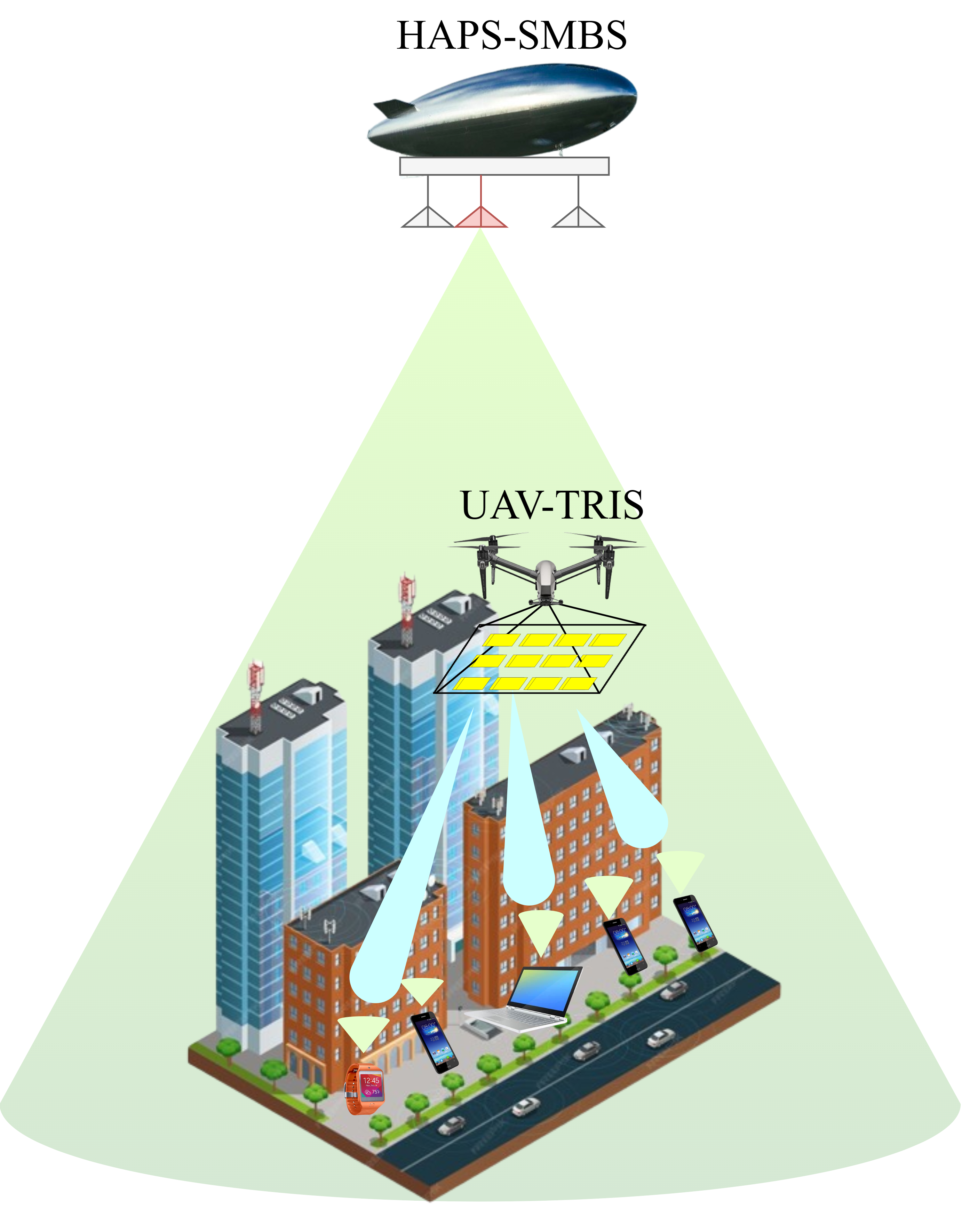
As presented in Fig. 1, our proposed system consists of a single HAPS-SMBS with an number of antennas, a single UAV, TRIS with elements, and IoT ground devices. We consider the TRIS to be deployed on UAV, and NOMA is used as a multiple-access technology to serve the IoT ground devices. It is assumed that the HAPS-SMBS acts as a transmitter (i.e., base station), and the UAV-TRIS operates as a relay. IoT ground devices receive two signals: A direct signal from the HAPS-SMBS and an indirect signal through the UAV-TRIS. We consider practical limitations (e.g., HWI) that exist in the HAPS-SMBS and IoT ground devices. It is assumed that the channel state information is available at all the nodes. The details of the system model are provided in the following paragraphs.
II-A HAPS-SMBS and UAV without TRIS
We consider that in addition to the direct link between the HAPS-SMBS and IoT ground devices, there is also an indirect link through the UAV. The UAV operates as a relay node, which uses the AF protocol, and we consider the UAV to have a single receiver and transmitter antenna. The HAPS-SMBS communicates with IoT ground devices using NOMA; thus, the HAPS-SMBS transmits a superimposed coding signal with different power allocation coefficients according to channel gain (i.e., channel gain for direct links and channel gain for indirect links ) to IoT ground devices directly and through UAV. The UAV amplifies the received signal and forwards it to the IoT ground devices using its power. Thus, the received signal through a direct and indirect links at IoT ground devices is given by
| (1) |
where , , is the power allocation coefficients, in which and , is the signals of IoT ground devices, and are the transmit power of HAPS-SMBS and UAV, respectively. is the additive white Gaussian noise (AWGN) which follows . , , , , , and are the independent distortion noise terms defined as [7, 8] and in which , , , , , and represent levels of impairment at the transceiver, respectively. According to [7, 8], the impact of transceiver HWI can be measured by the aggregate level of impairments, , , and . The Rician distribution channel vector between the HAPS-SMBS and UAV, denoted by , can be given as
| (2) |
while the Rician distribution channel vector between the UAV and IoT ground devices, denoted by , is as follows
| (3) |
and the Rician distribution channel vector between HAPS-SMBS and IoT ground devices, denoted by , is as follows
| (4) |
where represents the Rician factors, , , and are the large-scale path-loss coefficient between the HAPS-UAV, UAV-IoT ground devices, and HAPS-IoT ground devices, respectively. , , and are the line of sight (LoS) components of the corresponding channels, , , and are the non-line of sight (NLoS) components of the corresponding channels, which consists of complex Gaussian random variables with unit variance and zero mean that are independently and identically distributed. We assume that the antenna at HAPS-SMBS is selected for transmission (called TAS) to find the best channel condition of the HAPS-SMBS UAV and HAPS-SMBS IoT ground devices links as in [14], which are given as
| (5) |
and
| (6) |
IoT ground devices detect their signals based on power allocation distribution. Signal power levels are sorted in descending order, and detection follows this order. With the presence of HWI, the signal-to-interference-plus-noise ratio (SINR) for IoT ground devices is given by
| (7) |
where and .
Hence, the sum rate of the IoT ground devices can then be computed by
| (8) |
II-B HAPS-SMBS and UAV Equipped with Passive/Active TRIS
As shown in Fig. 1, the TRIS composed of elements is used in scenarios when the single antenna IoT ground devices are on the opposite side of the HAPS-SMBS (i.e., the incident signals penetrate through the TRIS elements). It is assumed that direct links are available between HAPS-SMBS and IoT ground devices. A passive TRIS is made up of many passive components, each of which can forward the incoming signal with a phase shift that can be adjusted. Typically, every component in a passive TRIS is composed of a patch connected to an impedance-adjustable circuit for phase control. Passive RIS element consumes almost no direct-current power because of their passive operational setting, which is devoid of active radio-frequency components, and any associated thermal noise is typically minor [4]. As presented in Fig. 1, the HAPS-SMBS transmits a superimposed coding signal with different power allocation coefficients according to channel gain (i.e., ) to IoT ground devices through UAV-RIS. Thus, the received signal at IoT ground devices with element is given by
| (9) |
where is the thermal noise introduced by active TRIS components, is a diagonal phase-shifting matrix that fully captures the characteristics of the TRIS, the phase shift of the -th TRIS reflecting element. The Rician distribution channel vector between the HAPS-SMBS and UAV-TRIS, denoted by , can be given as
| (10) |
and the Rician distribution channel vector between the UAV-TRIS and IoT ground devices, denoted by , can be given as
| (11) |
in which , , , and are the LoS and NLoS components of the corresponding channels, , , , and are the independent distortion noise terms defined as [7, 8] and We assume ; hence, we have for passive RIS, whereas for active RIS because of its amplifiers. We assume that the TAS is used at HAPS-SMBS to find the best channel condition of the HAPS-SMBS UAV link as given by
| (12) |
ToT ground devices detect their signals based on power allocation distribution, starting with the strongest and then the next in sequence.Assuming that the HWI exists, the SINR at IoT ground devices is given by
| (13) |
where and .
The sum rate of the IoT ground devices is given by
| (14) |
II-C 3GPP Path-loss Model
Since platforms operate at varying altitudes and may thus encounter different attenuation phenomena, we employ realistic path-loss models as specified by 3GPP [2, 1], where path-loss of the links from HAPS-SMBS to UAV, HAPS-SMBS to IoT ground devices, and UAV to IoT ground devices are defined. According to their relatively low altitude, UAV are typically taken to have full LoS conditions, thereby, the path-loss in an urban environment can be given as in [2, 1] by
| (15) |
where is the log-normal distribution with a standard deviation given by , is the distance between UAV and IoT ground devices, and is the attitude of UAV.
Additionally, the path-loss of HAPS-SMBS for the conditions of LoS and NLoS, for the link HAPS-SMBS UAV, can be given as in [2, 1] by
| (16) |
and for HAPS-SMBS IoT ground devices link is given by
| (17) |
where , , , and are the parameters that depend on the environment, which are determined in [1], and are the distance between HAPS-SMBS and IoT ground devices, and between HAPS-SMBS and UAV, respectively, and are the elevation angle, and are the basic path-loss, is the attenuation due to atmospheric gasses, is the attenuation due to either ionospheric, is the building entry loss, and are the free-space propagation loss, and are the clutter loss, is the shadow fading, and is the operation frequency.
III Energy Efficiency
Energy efficiency of HAPS-SMBS assisted UAV with AF and active/passive UAV-TRIS for the NOMA networks can be calculated as the sum rates divided by total power consumption. As shown in [15, 16], the energy efficiency of HAPS-SMBS assisted UAV with AF and active/passive UAV-TRIS for NOMA networks can be given as
| (18) |
where , , and is the total power consumption of UAV with AF and active/passive UAV-TRIS can be modeled as in [15, 16] by
| (19) |
where , , , is the output signal power of active TRIS, is the power consumed by the phase shift switch and control circuit in each TRIS element, is the direct current biasing power used by each active TRIS element, is the hardware power dissipated of the -th IoT ground devices, is the constant circuit power, and is the UAV power.
IV Landing Station Design and Use Case
IV-A Landing Station
Previous research as in [13] indicates that the power consumption due to flight is considerably more than the power consumption of the UAV when the UAV is used as a base station or relay. This reveals a crucial trade-off between flight and transmission power, suggesting that conserving flight power can extend the lifespan of UAV-TRIS in wireless networks. Implementing designated landing spots allows UAV-TRIS to rest without interrupting transmissions, addressing issues of high power consumption and short mission duration. Strategically locating these spots can minimize flight time, enhancing operational efficiency by optimizing power consumption. These areas, such as authorized rooftops or specific zones, provide opportunities for UAV-TRIS to recharge and continue operations without the need for additional recharging. Furthermore, UAV-TRIS can identify weak network spots and find optimal stopping points to maintain coverage efficiently.
IV-B Use Case: Joint Optimization of UAV Trajectory and Flight Control
The UAV must arrive at its destination without depleting its battery (especially with much consumption power of TRIS). This involves selecting the best trajectory and controlling the UAV. The optimization problem can be formulated as maximizing the sum rate of IoT devices by selecting the optimal flight trajectory while controlling the UAV’s speed and heading angle to guarantee effective data transfer while conserving energy. The optimal control problem can be formulated by
| (20a) | |||
| (20b) | |||
| (20c) | |||
| (20d) | |||
| (20e) | |||
where is the weight assigned to IoT, is the velocity, is the heading angle (in azimuth) of the UAV, is the maximum velocity, and denote the model of the UAV’s mobility, which are given by and . presents the maximum velocity at which the UAV can travel. demonstrates the amount of energy in the battery throughout the mission, in which the maximum available energy budget is referred by (this battery offers power that is utilized for both flying and communication). represents the total mission duration, in which .
This novel method seeks to overcome the practical challenges of UAV-TRIS-assisted networks, including the requirement to regularly swap out UAV when their batteries run out. The concept of landing stations for UAV-TRIS-assisted wireless networks represents a promising way to improve network capacity performance and efficiency in real-world deployment scenarios. It is important to mention that this problem is non-convex due to complex constraints and non-linearity, requiring specialized methods to solve it.
V Numerical Results
In this section, the simulation results of the proposed system in terms of the sum rate and energy efficiency are obtained and compared with three schemes: Conventional single-input single-output with HAPS-SMBS assisted UAV-TRIS, HAPS-SMBS-assisted UAV with AF supported by TAS, and HAPS-SMBS-assisted passive UAV-TRIS supported by TAS. We discuss the effect of HWI on the performance of our system. Without loss of generality, we consider that and . The parameters used in all simulations are given by , , , , dB, dB, dBm, dBm, Ghz, , m, m, km, km, km, m, dB, and [1].
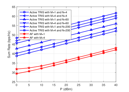
In Fig. 2, we present the sum rate of HAPS-SMBS with TAS-assisted active UAV-TRIS with different numbers of TRIS elements () and antenna () in the absence of HWI. We observe that the proposed system outperforms HAPS-SMBS with TAS-assisted UAV using AF. The increasing and increase the sum rate performance. It can be seen that increasing is more effective than in enhancing overall performance. Increasing improves the system performance of the proposed system by compared to UAV-AF and it increased with increasing. To evaluate the effect of increasing on the system performance, in Fig. 3 (a), we compare energy efficiency of active HAPS-SMBS with TAS-assisted UAV-TRIS and HAPS-SMBS with TAS-assisted UAV using AF under the effect of HWI, when and . We observe that the proposed system achieves higher performance gain compared to the HAPS-SMBS with TAS-assisted UAV using AF in the lower values. It is observed that increasing reduces energy efficiency performance, and this occurs due to more energy being consumed. Moreover, the HWI limits the energy efficiency performance, further affected by high values of , , and transmit power.
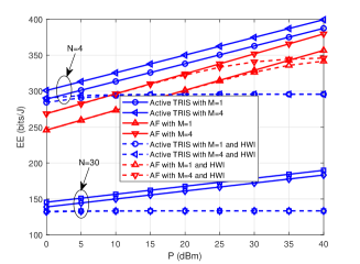
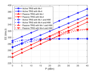
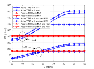
The energy efficiency of the proposed system with active and passive TRIS is demonstrated in Fig. 3 (b) with different numbers of antennas under the effect of HWI when and . It is seen that the active TRIS has a higher performance gain than the passive TRIS. For this reason, the signal strength received at the IoT ground devices can be greatly enhanced by active TRIS, which can use an amount of power to amplify the signal that was attenuated after the transmission in the first phase. Again, the HWI has a significant impact on the performance of the system at high power levels. As we can see, the HWI has a greater negative impact on the active TRIS due to the power amplification factor. To present the impact of the amplification factor on the system performance, Fig. 3 (c) illustrates the energy efficiency of the proposed system with active and passive TRIS w.r.t. under the impact of HWI when and . We observe that increasing improves the performance of the active TRIS compared to the passive TRIS. However, increasing reduces the energy efficiency performance in active more than passive TRIS due to the larger energy consumed. In the presence of HWI, on the other hand, the performance becomes limited again despite increasing the number of and . HWI affects system performance more than the thermal noise from active TRIS components.
VI Conclusion
In this paper, we proposed integrating active TRIS on UAV to enhance the capabilities of a HAPS-SMBS-enabled TAS system. This approach is designed to serve IoT ground devices employing NOMA technology. For a practical scenario, the presence of HWI is taken into account in our proposed system, and thus the sum rate and energy efficiency of the proposed system were obtained under the effect of HWI. As a benchmark, the proposed system is compared with three schemes: Conventional single-input single-output with HAPS-SMBS assisted UAV-TRIS, HAPS-SMBS enabled by TAS-assisted UAV without TRIS, and HAPS-SMBS with TAS-assisted passive UAV-TRIS. The results revealed that the proposed system achieves a higher performance gain compared to the benchmarks. Moreover, the increasing number of TRIS elements increases the sum rate performance; however, it consumes a higher power compared to passive TRIS. The HWI limited the system performance at the high transmit power levels despite the increased number of TRIS elements. UAV consume more energy due to flying than transmitting (i.e., when used in a wireless network). To improve the performance and reduce the power consumption of UAV, the landing spot approach was proposed. Future work will include and solve the optimization of the proposed landing spot design to enhance operational efficiency by optimizing power consumption and efficiency in real-world deployment scenarios.
Acknowledgment
This study is supported in part by the Study in Canada Scholarship (SICS) by Global Affairs Canada, in part by The Scientific and Technological Research Council of Türkiye (TUBITAK), and in part by the Discovery Grant RGPIN-2022-05231 from the Natural Sciences and Engineering Research Council of Canada (NSERC).
References
- [1] S. Alfattani, W. Jaafar, Y. Hmamouche, H. Yanikomeroglu, and A. Yongacoglu, “Link budget analysis for reconfigurable smart surfaces in aerial platforms,” IEEE Open J. Commun. Soc., vol. 2, pp. 1980–1995, 2021.
- [2] 3GPP, “Study on channel model for frequencies from 0.5 to 100 GHz,” 2018.
- [3] “IMT towards 2030 and beyond,” ITU, Accessed: Apr. 5, 2024. [Online]. Available: http:https://www.itu.int/en/ITU-R/study-groups/rsg5/rwp5d/imt-2030/Pages/default.aspx.
- [4] Z. Zhang, L. Dai, X. Chen, C. Liu, F. Yang, R. Schober, and H. V. Poor, “Active RIS vs. passive RIS: Which will prevail in 6G?” IEEE Trans. Commun., vol. 71, no. 3, pp. 1707–1725, 2022.
- [5] N. Gao, S. Jin, X. Li, and M. Matthaiou, “Aerial RIS-assisted high altitude platform communications,” IEEE Wirel. Commun. Lett., vol. 10, no. 10, pp. 2096–2100, 2021.
- [6] T. V. Nguyen, H. D. Le, and A. T. Pham, “On the design of RIS–UAV relay-assisted hybrid FSO/RF satellite-aerial-ground integrated network,” IEEE Trans. Aero. Elect. Sys., vol. 59, no. 2, pp. 757–771, 2022.
- [7] S. Beddiaf, A. Khelil, F. Khennoufa, F. Kara, H. Kaya, X. Li, K. Rabie, and H. Yanikomeroglu, “A unified performance analysis of cooperative NOMA with practical constraints: Hardware impairment, imperfect SIC and CSI,” IEEE Access, vol. 10, pp. 132 931–132 948, 2022.
- [8] F. Khennoufa, K. Abdellatif, F. Kara, H. Yanikomeroglu, K. Rabie, T. Y. Elganimi, and S. Beddiaf, “Error performance analysis of UAV-mounted RIS for NOMA systems with practical constraints,” IEEE Commun. Lett., vol. 28, no. 4, pp. 887–891, 2024.
- [9] X. Yang, H. Wang, and Y. Feng, “Sum rate maximization for active RIS-aided uplink multi-antenna NOMA systems,” IEEE Wirel. Commun. Lett., vol. 12, no. 7, pp. 1149–1153, 2023.
- [10] X. Yue, M. Song, C. Ouyang, Y. Liu, T. Li, and T. Hou, “Exploiting active RIS in NOMA networks with hardware impairments,” IEEE Tran. Veh. Tech, (Early Access), 2024.
- [11] S. Zeng, H. Zhang, B. Di, Y. Tan, Z. Han, H. V. Poor, and L. Song, “Reconfigurable intelligent surfaces in 6G: Reflective, transmissive, or both?” IEEE Commun. Lett., vol. 25, no. 6, pp. 2063–2067, 2021.
- [12] I. WP5D, “Draft new recommendation ITU-R M.[IMT. Framework for 2030 and beyond],” 2023.
- [13] R. Gangula, D. Gesbert, D. F. Külzer, and J. M. Franceschi, “A landing spot approach for enhancing the performance of UAV-aided wireless networks,” in IEEE Internat. Conf. Commun. Workshops (ICC Workshops), 2018, pp. 1–6.
- [14] D.-D. Tran, H.-V. Tran, D.-B. Ha, and G. Kaddoum, “Secure transmit antenna selection protocol for MIMO NOMA networks over Nakagami-m channels,” IEEE Sys. J., vol. 14, no. 1, pp. 253–264, 2019.
- [15] K. Zhi, C. Pan, H. Ren, K. K. Chai, and M. Elkashlan, “Active RIS versus passive RIS: Which is superior with the same power budget?” IEEE Commun. Lett., vol. 26, no. 5, pp. 1150–1154, 2022.
- [16] O. Amin, E. Bedeer, M. H. Ahmed, O. A. Dobre, and M.-S. Alouini, “Opportunistic energy-aware amplify-and-forward cooperative systems with imperfect CSI,” IEEE Trans. Veh. Tech., vol. 65, no. 7, pp. 4875–4886, 2015.