Implementing a synthetic magnetic vector potential
in a 2D superconducting qubit array
Abstract
Superconducting quantum processors are a compelling platform for analog quantum simulation due to the precision control, fast operation, and site-resolved readout inherent to the hardware. Arrays of coupled superconducting qubits natively emulate the dynamics of interacting particles according to the Bose-Hubbard model. However, many interesting condensed-matter phenomena emerge only in the presence of electromagnetic fields. Here, we emulate the dynamics of charged particles in an electromagnetic field using a superconducting quantum simulator. We realize a broadly adjustable synthetic magnetic vector potential by applying continuous modulation tones to all qubits. We verify that the synthetic vector potential obeys requisite properties of electromagnetism: a spatially-varying vector potential breaks time-reversal symmetry and generates a gauge-invariant synthetic magnetic field, and a temporally-varying vector potential produces a synthetic electric field. We demonstrate that the Hall effect—the transverse deflection of a charged particle propagating in an electromagnetic field—exists in the presence of the synthetic electromagnetic field.
I Introduction
Analog quantum simulators emulate physical models of materials systems to elucidate their properties [1, 2, 3, 4, 5, 6]. At scale, these devices will operate in a regime that is intractable for classical computers, possibly providing scientific utility before quantum error correction enables general-purpose digital simulation [7, 8, 9, 10]. Ideally, the hardware should be able to emulate models describing a variety of materials systems. One important class of models describes electronic systems in materials where time-reversal symmetry is broken by a magnetic field. Magnetic fields are required to access many quantum phases of matter, including certain topological states [11, 12, 13, 14], and are needed to observe several features of electrical transport [15, 16, 17, 18].
Arrays of coupled superconducting qubits natively emulate tight-binding models. The qubits represent the lattice sites, qubit excitations correspond to bosonic particles, and nearest-neighbor exchange interactions are realized by resonantly coupling adjacent qubits [19, 20, 21, 22, 23, 24]. The ensuing dynamics respect time-reversal symmetry and therefore cannot emulate an electronic system in a magnetic field without adding a symmetry-breaking mechanism. Although applying an external magnetic field generally breaks time-reversal symmetry for systems with charged particles, here such an emulator would retain time-reversal symmetry since the qubit excitations are chargeless bosons.
In the absence of a physical magnetic field, one can alternatively use the Harper-Hofstadter (HH) model,
| (1) |
to emulate the dynamics of charged particles moving in a two-dimensional (2D) lattice in the presence of a perpendicular magnetic field [25, 26]. Emulation of the HH model with uniform fields has been demonstrated with atomic simulators, where laser-assisted tunneling in a tilted optical lattice was used to set the phases and thereby break time-reversal symmetry [27, 28, 29], and in an array of microwave cavities, where ferrimagnetic inserts placed in certain cavities set the phases [30]. Superconducting simulators comprising 1D qubit arrays have realized the Aubry-André-Harper model, a related model that mimics the HH spectrum but not its dynamics as time-reversal symmetry is unbroken [31, 32, 33, 34]. Realizing the HH model with individually and dynamically adjustable phases would enable a generalized emulator for particles in magnetic and electric fields via a (time-dependent) magnetic vector potential.
In this work, we directly emulate the HH model using a 2D array of superconducting qubits by applying several control tones that together break time-reversal symmetry. Our system comprises 16 transmon qubits [35] with fixed capacitive coupling between adjacent qubits. Instead of resonantly coupling the qubits, we detune adjacent qubits from one another and parametrically induce exchange interactions by modulating the qubits with control tones matching the detuning frequencies [36, 37]. The phases of the modulation tones constitute a synthetic vector potential. When the modulation tones have nonzero relative phases, time-reversal symmetry is broken and the processor adopts a synthetic perpendicular magnetic field. When the phases vary in time, spatial-inversion symmetry is broken and the processor adopts a synthetic electric field according to Faraday’s law of induction [38]. A broad range of electromagnetic field strengths and profiles, including spatially nonuniform and time-varying fields, can be emulated.
Using this emulator, we replicate several hallmark features of two-dimensional electronic systems in the presence of electromagnetic fields. We observe Aharonov-Bohm interference in rings of various lengths and verify the interference patterns are invariant to the choice of gauge. We show that particles in a synthetic electric field exhibit Bloch oscillations rather than uniform motion. Finally, upon simultaneous application of synthetic electric and magnetic fields, we observe the Hall effect: a propagating particle is deflected transversely to both fields.
II Methods
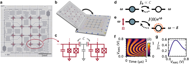
Our experiment is implemented on a superconducting quantum processor comprising 16 flux-tunable transmon qubits arranged in a grid (Fig. 1a). Individual flux control lines and readout resonators are located on a separate chip arranged and brought in proximity to the qubits using a flip-chip configuration (Fig. 1b) [39]. The processor is discussed in more detail in Refs. [40, 24]. Nearest neighbors are transversely coupled through a fixed mutual capacitance (Fig. 1c), realizing—within the rotating-wave approximation—the Bose-Hubbard model
| (2) |
where is the number operator corresponding to the bosonic annihilation operator for a particle on site . Adjacent sites are coupled by the particle exchange interactions
| (3) |
where the summation extends over the nearest-neighbor pairs in the lattice. Here, a particle on site corresponds to an excitation of qubit , and we refer to as its population. The on-site energies are individually adjustable through the flux control lines. The on-site interactions arise from the qubit anharmonicities and have an average strength , and the bare exchange interactions have real coefficients with an average strength . For the remainder of this work, we consider only the single-particle manifold of Eq. (2) and therefore omit the on-site interaction term for brevity.
Typically, superconducting analog simulators operate with all sites resonant (uniform ) so that particles hop between sites at rate (Fig. 1d). Such simulators respect time-reversal symmetry and emulate materials without a magnetic field. To emulate the dynamics of charged particles in an electromagnetic field, we wish to create a synthetic vector potential that generates analogous dynamics for photons in the lattice. Through a Peierls substitution [41], maps to the Bose-Hubbard lattice as complex coefficients on the exchange terms. Known as Peierls phases, the complex phases are equivalent to written in dimensionless units (a derivation is provided in the Supplementary Information). To realize nonzero Peierls phases on each nearest-neighbor interaction, we employ a parametric coupling scheme, shown schematically in Fig. 1e. Consider two neighboring qubits and . We adjust their frequencies to establish a detuning and sinusoidally modulate the on-site energy of qubit with frequency , realizing the lab-frame Hamiltonian
| (4) |
where is the modulation amplitude of qubit and is the Peierls phase.
Transforming Eq. (4) into the instantaneous rotating frame of both sites yields a Hamiltonian containing stationary terms
| (5) |
where is the first-order Bessel function of the first kind, revealing that parametric modulations induce complex hopping. The Peierls phase is the phase of the modulation . Additional terms rotating at multiples of are discussed in the Supplementary Information. We demonstrate experimentally that the hopping rate can be tuned by varying , reaching a maximum value (Fig. 1f, 1g), the maximum of .
Extending the parametric coupling throughout the qubit array emulates the HH model. We note that, in our coupling scheme, the second qubit is also modulated at to induce parametric hopping to subsequent lattice sites, and so on. Choosing unequal values for all neighboring sites , enables full tunability of the synthetic vector potential; the layout of detunings and modulations is detailed in the Supplementary Information. For the remainder of this work, the modulation of each qubit is chosen to provide a hopping rate to its neighbor when the latter is not modulated. The hopping rate is reduced by a factor of approximately when site is also modulated (see the Supplementary Information). The effective hopping rates are therefore approximately , such that .
Secondly, we note that in Eq. (5), we present the parametric modulation as a sinusoid in the qubit frequency. In practice, we modulate the qubits sinusoidally in flux bias. Because the qubits are operated in the linear regime of their spectra, the two types of modulation are equivalent to first order and differences are insignificant at the utilized modulation amplitudes. Thirdly, we note that may be positive or negative; both signs are used in the experiment. When , the sign of the Peierls phase is opposite that of the modulation phase. Lastly, the experimental data presented in this work are based on simultaneous single-shot population measurements of all active qubits. Before determining the population on each site by averaging single-shot results, the single-shot data are post-selected on total population to partially mitigate relaxation and readout infidelity.
III Results and Discussion
The dynamics of a particle hopping between two sites alone does not depend on the Peierls phase of the intervening exchange coupling. To observe Peierls phase-dependent dynamics, we need to consider a set of sites forming a closed path, in which case the dynamics will depend on the dimensionless synthetic magnetic flux, which takes real values modulo ,
| (6) |
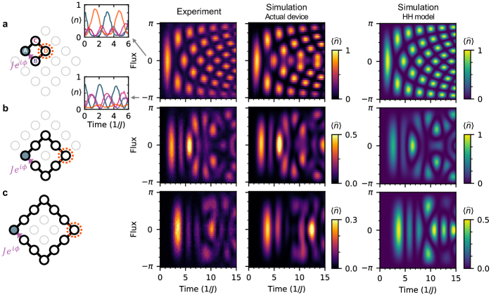
where the summation is taken along the closed oriented path forming the boundary of a surface , emulating a charged particle with magnetic flux quantum in a magnetic field . To demonstrate this, we consider four qubits arranged in a plaquette, labeled A–D as shown in Fig. 2a. D is modulated at the detuning between D and qubits B and C (B and C are set to identical frequencies); B and C are modulated at the detuning between themselves and A. The flux through the plaquette is the relative phase difference between the modulations of B and C, and is invariant to the modulation phase of qubit D (which, according to Eq. (6), contributes no net flux). All other qubits in the array are deactivated by detuning them far () from the active qubits.
We first consider the case . After a particle is initialized at A by a microwave -pulse, it propagates to D through a quantum walk [20, 42, 23] along two trajectories, one via B and the other via C. As no relative phase is accumulated, the two trajectories constructively interfere, and the particle arrives at D (Fig. 2a, upper inset). When the modulation of B is shifted by , inverting the sign of hopping between B and A so that , the two trajectories accumulate opposing signs and destructively interfere. In this case, the particle cannot reach D and reflects back to A (Fig. 2a, lower inset). This effect is known as Aharonov-Bohm caging, and was recently demonstrated in a superconducting processor using different methodology [43].
Here, we can extend the experiment to arbitrary Peierls phases. In Fig. 2a, we present the population of D as the modulation phase of B is varied from to , yielding an Aharonov-Bohm interference pattern dependent on the synthetic magnetic flux [15]. The parametric driving scheme can also be extended to larger rings. In Fig. 2b and Fig. 2c, we present Aharonov-Bohm interference patterns in - and -site rings, respectively, with the enclosed qubits inactive (far detuned). As before, these measurements begin with a single particle initialized on one corner of the ring, and we present the population on the opposing corner as a function of time and flux. Again, we observe constructive interference at , destructive interference at , and an intricate interference pattern between.
In Fig. 2 and throughout the remainder of this work, two layers of numerical simulations accompany experimental data. We first present a decoherence-free simulation of our system as it is operated (“actual device”), using the lab-frame Hamiltonian Eq. (4) with measured values of each nearest- and next-nearest-neighboring bare exchange interaction strength . For computational efficiency, each site is modeled as a two-level system. The agreement between experimental and simulated results verifies faithful realization of the parametric coupling scheme on the superconducting processor. Second, we present simulation of the idealized HH model Eq. (1) with uniform nearest-neighbor coupling only. The qualitative similarity between experimental data and the latter simulation verifies that, with the parametric coupling scheme, we indeed emulate particles moving in a magnetic field.
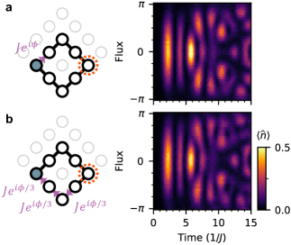
As implied by Eq. (6), the dynamics of our system should be invariant to the choice of Peierls phases provided that the flux through each plaquette is conserved. This property is a manifestation of the gauge invariance of magnetic vector potentials. To verify gauge invariance, we perform further Aharonov-Bohm interferometry experiments in the -site ring, but with different arrangements of the Peierls phases. In Fig. 3a, the Peierls phase is placed on an exchange coupling on the upper trajectory across the ring, rather than the lower trajectory. In Fig. 3b, is distributed between Peierls phases placed on three exchange couplings, each with value . Both cases are related to the original case presented in Fig. 2b by gauge transformations, i.e., by transformations for scalar fields (depicted visually in the Supplementary Information). The transformations conserve . In all cases, we observe similar interference patterns, demonstrating the synthetic magnetic field upholds gauge freedom.
Up to this point, we have discussed the dynamics of particles when the synthetic vector potential is static. A time-varying vector potential contributes to the electric field according to Faraday’s law of induction
| (7) |
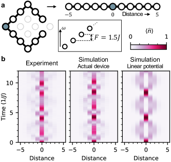
Varying the Peierls phases in time as , or, equivalently, shifting the modulation frequencies by , should therefore generate a synthetic electric field per site. To test Faraday’s law, we use 11 perimeter sites of the superconducting processor as a one-dimensional chain with open boundaries (Fig. 4a), and shift the modulation frequency by for every exchange coupling. We initialize a particle on the central site of the chain; its subsequent motion is displayed in Fig. 4b. Instead of propagating to the boundary of the chain and reflecting, the particle remains confined near the central site. The confinement reflects Wannier-Stark localization of the particle from the synthetic electric field [44, 45, 23], which can be understood in a momentum-space picture as a consequence of Bloch oscillations or in a real-space picture as confinement of the particle to sites having an effective energy within of the initial site’s energy. Indeed, the dynamics match simulations of a tight binding model with a linear potential,
| (8) |
verifying that a synthetic electric field is established.
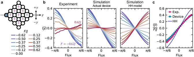
The Hall effect is a well-known feature of electrical conductors in a perpendicular magnetic field where particles deflect transverse to the direction of current flow. To emulate the Hall effect, we study the dynamics of a particle in the full -site array with equal flux threading each plaquette, creating a uniform synthetic magnetic field (Fig. 5a). We additionally induce a synthetic longitudinal electric field per lattice constant via Faraday’s law. We initialize a particle at a corner of the lattice so that its initial average velocity is longitudinal and preserves the mirror symmetry of the lattice about the line (dashed line in Fig. 5a), and we measure the population of all sites as a function of time.
For an electrical conductor, the Hall voltage quantifies the transverse deflection of charge carriers in the presence of a magnetic field. Here, we directly measure the average distance of the particle from the axis, and consider its time-averaged value throughout the first of the experiment—approximately the time needed for the particle to reach the opposite corner of the array. Data and corresponding simulations are shown at various magnetic and electric field strengths in Fig. 5b.
We first describe simulations of an idealized model comprising the HH model and a linear potential . When , the particle is not deflected, even in finite magnetic field. This feature is surprising: given the initial longitudinal velocity of the particle, from a classical description one would expect a transverse Lorentz force since . In the Supplementary Information we show through a semi-classical momentum-state expansion that symmetries of the particle’s wavepacket imply that its net transverse velocity is odd in both and . Therefore, even as the particle moves longitudinally across the lattice, only when and are both nonzero does the particle deflect transversely.
In the experiment, we instead observe transverse deflection when . This deflection is primarily due to inhomogenity in , which breaks the symmetries noted above, and effectively skews the deflection as a function of flux at (see the Supplementary Information). Aside from this skew, the deflection trends roughly linearly in flux and in , matching the idealized model. Simulations of the actual device closely reproduce the experimental results.
To summarize these data, in Fig. 5c we present the transverse deflection per unit electric field, determined by linear fits to the data in Fig. 5b, as a function of synthetic flux. This linearized quantity may be compared to the Hall resistance of an electrical conductor, which in general is proportional to magnetic field for small fields. Surprisingly, in our system the transverse deflection trends with but not with the average longitudinal velocity, which is the same for (data in the Supplementary Information). This behavior differs from dissipative electrical conductors where, according to the Drude model, the longitudinal drift velocity is proportional to electric field (so the transverse deflection trends with both). The Hall effect in our system therefore cannot be described through the classical Lorentz force from the particle’s net velocity, but is consistent with a semi-classical description that considers the evolution of the particle’s wavepacket.
IV Conclusion
In this work, we emulate a tight-binding lattice in a spatially and temporally adjustable magnetic vector potential using a 2D array of superconducting qubits. We verify the presence of the synthetic vector potential by observing Aharonov-Bohm interference in rings of various sizes, where transport across the two interferometer arms accumulate phases differing by the enclosed magnetic flux. We confirm that the synthetic vector potential behaves consistently with two of Maxwell’s equations: Gauss’s law for magnetism , which is equivalent to a statement of its gauge freedom, and Faraday’s law, which connects electric and magnetic fields. Finally, we demonstrate transverse deflection of a particle traveling in the synthetic electromagnetic field. While a classical Lorentz force is often invoked to explain the Hall effect, it does not accurately describe the dynamics of our system. Our results therefore showcase that the ballistic propagation of a quantum particle in a lattice differs from the motion of a free particle. The realization of other members of the family of Hall effects, including the integer and fractional quantum Hall effects, is possible using the methods described in this work.
In the present experiment, we generate synthetic electromagnetic fields by parametrically modulating qubits that are coupled by fixed mutual capacitances. The scheme may be viewed as the analog limit of a scheme recently used to approximate a magnetic field through repeated digital gates [46]. Alternatively, synthetic fields may be generated by modulating tunable-coupling elements [47, 48, 49] with the qubits held static [50]. Tunable couplers confer simplified control of each parametrically-induced exchange coupling at the expense of additional hardware overhead.
The techniques introduced here extend beyond the emulation of natural 2D materials. The synthetic magnetic flux through each unit cell of the qubit lattice may be individually set to any desired value modulo . In contrast, creating magnetic-field patterns at the nanoscale or even mesoscale is difficult in natural materials, as is reaching high values of flux per unit cell. For example, a half-magnetic-flux-quantum per unit cell in graphene would require approximately a field. Our methodology therefore provides a new platform for creating artificial matter in high magnetic fields—for example, Hofstadter subband states [26, 51, 52]—or complex magnetic environments—for example, the Haldane model [53, 54] and domain walls in Chern insulators [55, 56].
Note: While preparing this manuscript, we became aware of related work using parametrically modulated coupling elements to generate a synthetic magnetic field [57].
V Acknowledgements
The authors are grateful to Patrick M. Harrington, Jeffrey M. Gertler, Aaron L. Sharpe, Brice Bakkali-Hassani, Xiao-Gang Wen, and Terry P. Orlando for fruitful discussions. This material is based upon work supported in part by the U.S. Department of Energy, Office of Science, National Quantum Information Science Research Centers, Quantum System Accelerator (QSA); in part by the Defense Advanced Research Projects Agency under the Quantum Benchmarking contract; in part by U.S. Army Research Office Grant W911NF-18-1-0411; in part by the U.S. Department of Energy, Office of Science, National Quantum Information Science Research Centers, Co-design Center for Quantum Advantage (C2QA) under contract number DE-SC0012704; and in part by the Department of Energy and Under Secretary of Defense for Research and Engineering under Air Force Contract No. FA8702-15-D-0001. ITR and MH are supported by an appointment to the Intelligence Community Postdoctoral Research Fellowship Program at the Massachusetts Institute of Technology administered by Oak Ridge Institute for Science and Education (ORISE) through an interagency agreement between the U.S. Department of Energy and the Office of the Director of National Intelligence (ODNI). SM is supported by a NASA Space Technology Research Fellowship. AC is partially supported by NSF DMR-2022428. DAR acknowledges support from the National Science Foundation under award DMR-1747426. Any opinions, findings, conclusions, or recommendations expressed in this material are those of the author(s) and do not necessarily reflect the views of the Department of Energy, the Department of Defense, or the Under Secretary of Defense for Research and Engineering.
VI Author Contribution
ITR, AC, MH, and MAD developed the theory for this work. ITR, SEM, and CNB performed the experiments. AHK developed infrastructure with support from DAR. RD, DKK, BMN, and MS fabricated the device with coordination from KS, MES, and JLY. JAG and WDO provided technical oversight and support. ITR wrote the manuscript with contributions from all authors.
VII Competing Interests
The Authors declare no competing interests.
References
- Greiner et al. [2002] M. Greiner, O. Mandel, T. Esslinger, T. W. Hänsch, and I. Bloch, Nature 415, 39 (2002).
- Houck et al. [2012] A. A. Houck, H. E. Türeci, and J. Koch, Nature Physics 8, 292 (2012).
- Georgescu et al. [2014] I. M. Georgescu, S. Ashhab, and F. Nori, Rev. Mod. Phys. 86, 153 (2014).
- Scholl et al. [2021] P. Scholl, M. Schuler, H. J. Williams, A. A. Eberharter, D. Barredo, K.-N. Schymik, V. Lienhard, L.-P. Henry, T. C. Lang, T. Lahaye, et al., Nature 595, 233 (2021).
- Altman et al. [2021] E. Altman, K. R. Brown, G. Carleo, L. D. Carr, E. Demler, C. Chin, B. DeMarco, S. E. Economou, M. A. Eriksson, K.-M. C. Fu, M. Greiner, K. R. Hazzard, R. G. Hulet, A. J. Kollár, B. L. Lev, M. D. Lukin, R. Ma, et al., PRX Quantum 2, 017003 (2021).
- Ebadi et al. [2021] S. Ebadi, T. T. Wang, H. Levine, A. Keesling, G. Semeghini, A. Omran, D. Bluvstein, R. Samajdar, H. Pichler, W. W. Ho, et al., Nature 595, 227 (2021).
- Preskill [2018] J. Preskill, Quantum 2, 79 (2018).
- Kandala et al. [2019] A. Kandala, K. Temme, A. D. Córcoles, A. Mezzacapo, J. M. Chow, and J. M. Gambetta, Nature 567, 491 (2019).
- Daley et al. [2022] A. J. Daley, I. Bloch, C. Kokail, S. Flannigan, N. Pearson, M. Troyer, and P. Zoller, Nature 607, 667 (2022).
- Kim et al. [2023] Y. Kim, A. Eddins, S. Anand, K. X. Wei, E. Van Den Berg, S. Rosenblatt, H. Nayfeh, Y. Wu, M. Zaletel, K. Temme, et al., Nature 618, 500 (2023).
- Schnyder et al. [2008] A. P. Schnyder, S. Ryu, A. Furusaki, and A. W. W. Ludwig, Phys. Rev. B 78, 195125 (2008).
- Qi and Zhang [2011] X.-L. Qi and S.-C. Zhang, Rev. Mod. Phys. 83, 1057 (2011).
- Alicea [2012] J. Alicea, Reports on Progress in Physics 75, 076501 (2012).
- von Klitzing et al. [2020] K. von Klitzing, T. Chakraborty, P. Kim, V. Madhavan, X. Dai, J. McIver, Y. Tokura, L. Savary, D. Smirnova, A. M. Rey, et al., Nature Reviews Physics 2, 397 (2020).
- Aharonov and Bohm [1959] Y. Aharonov and D. Bohm, Phys. Rev. 115, 485 (1959).
- Little and Parks [1962] W. A. Little and R. D. Parks, Phys. Rev. Lett. 9, 9 (1962).
- Hikami et al. [1980] S. Hikami, A. I. Larkin, and Y. Nagaoka, Progress of Theoretical Physics 63, 707 (1980).
- Taychatanapat et al. [2013] T. Taychatanapat, K. Watanabe, T. Taniguchi, and P. Jarillo-Herrero, Nature Physics 9, 225 (2013).
- Ma et al. [2019] R. Ma, B. Saxberg, C. Owens, N. Leung, Y. Lu, J. Simon, and D. I. Schuster, Nature 566, 51 (2019).
- Yan et al. [2019] Z. Yan, Y.-R. Zhang, M. Gong, Y. Wu, Y. Zheng, S. Li, C. Wang, F. Liang, J. Lin, Y. Xu, C. Guo, L. Sun, C.-Z. Peng, K. Xia, H. Deng, H. Rong, J. Q. You, F. Nori, H. Fan, X. Zhu, and J.-W. Pan, Science 364, 753 (2019).
- Yanay et al. [2020] Y. Yanay, J. Braumüller, S. Gustavsson, W. D. Oliver, and C. Tahan, npj Quantum Information 6, 58 (2020).
- Saxberg et al. [2022] B. Saxberg, A. Vrajitoarea, G. Roberts, M. G. Panetta, J. Simon, and D. I. Schuster, Nature 612, 435 (2022).
- Karamlou et al. [2022] A. H. Karamlou, J. Braumüller, Y. Yanay, A. Di Paolo, P. M. Harrington, B. Kannan, D. Kim, M. Kjaergaard, A. Melville, S. Muschinske, et al., npj Quantum Information 8, 35 (2022).
- Karamlou et al. [2023] A. H. Karamlou, I. T. Rosen, S. E. Muschinske, C. N. Barrett, A. Di Paolo, L. Ding, P. M. Harrington, M. Hays, R. Das, D. K. Kim, et al., arXiv:2306.02571 [quant-ph] (2023).
- Harper [1955] P. G. Harper, Proceedings of the Physical Society. Section A 68, 874 (1955).
- Hofstadter [1976] D. R. Hofstadter, Phys. Rev. B 14, 2239 (1976).
- Aidelsburger et al. [2013] M. Aidelsburger, M. Atala, M. Lohse, J. T. Barreiro, B. Paredes, and I. Bloch, Phys. Rev. Lett. 111, 185301 (2013).
- Miyake et al. [2013] H. Miyake, G. A. Siviloglou, C. J. Kennedy, W. C. Burton, and W. Ketterle, Phys. Rev. Lett. 111, 185302 (2013).
- Léonard et al. [2023] J. Léonard, S. Kim, J. Kwan, P. Segura, F. Grusdt, C. Repellin, N. Goldman, and M. Greiner, Nature 619, 495 (2023).
- Owens et al. [2022] J. C. Owens, M. G. Panetta, B. Saxberg, G. Roberts, S. Chakram, R. Ma, A. Vrajitoarea, J. Simon, and D. I. Schuster, Nature Physics 18, 1048 (2022).
- Aubry and André [1980] S. Aubry and G. André, Ann. Israel Phys. Soc 3, 18 (1980).
- Roushan et al. [2017a] P. Roushan, C. Neill, J. Tangpanitanon, V. M. Bastidas, A. Megrant, R. Barends, Y. Chen, Z. Chen, B. Chiaro, A. Dunsworth, et al., Science 358, 1175 (2017a).
- Li et al. [2023] H. Li, Y.-Y. Wang, Y.-H. Shi, K. Huang, X. Song, G.-H. Liang, Z.-Y. Mei, B. Zhou, H. Zhang, J.-C. Zhang, et al., npj Quantum Information 9, 40 (2023).
- Xiang et al. [2023] Z.-C. Xiang, K. Huang, Y.-R. Zhang, T. Liu, Y.-H. Shi, C.-L. Deng, T. Liu, H. Li, G.-H. Liang, Z.-Y. Mei, H. Yu, G. Xue, Y. Tian, X. Song, Z.-B. Liu, K. Xu, D. Zheng, F. Nori, and H. Fan, Nature Communications 14, 5433 (2023).
- Koch et al. [2007] J. Koch, T. M. Yu, J. Gambetta, A. A. Houck, D. I. Schuster, J. Majer, A. Blais, M. H. Devoret, S. M. Girvin, and R. J. Schoelkopf, Phys. Rev. A 76, 042319 (2007).
- Alaeian et al. [2019] H. Alaeian, C. W. S. Chang, M. V. Moghaddam, C. M. Wilson, E. Solano, and E. Rico, Phys. Rev. A 99, 053834 (2019).
- Zhao et al. [2022] S. K. Zhao, Z.-Y. Ge, Z. Xiang, G. M. Xue, H. S. Yan, Z. T. Wang, Z. Wang, H. K. Xu, F. F. Su, Z. H. Yang, H. Zhang, Y.-R. Zhang, X.-Y. Guo, K. Xu, Y. Tian, H. F. Yu, D. N. Zheng, H. Fan, and S. P. Zhao, Phys. Rev. Lett. 129, 160602 (2022).
- Lin et al. [2011] Y.-J. Lin, R. L. Compton, K. Jimenez-Garcia, W. D. Phillips, J. V. Porto, and I. B. Spielman, Nature Physics 7, 531 (2011).
- Rosenberg et al. [2017] D. Rosenberg, D. Kim, R. Das, D. Yost, S. Gustavsson, D. Hover, P. Krantz, A. Melville, L. Racz, G. O. Samach, S. J. Weber, F. Yan, J. L. Yoder, A. J. Kerman, and W. D. Oliver, npj Quantum Information 3, 1 (2017).
- Barrett et al. [2023] C. N. Barrett, A. H. Karamlou, S. E. Muschinske, I. T. Rosen, J. Braumüller, R. Das, D. K. Kim, B. M. Niedzielski, M. Schuldt, K. Serniak, M. E. Schwartz, J. L. Yoder, T. P. Orlando, S. Gustavsson, J. A. Grover, and W. D. Oliver, Phys. Rev. Appl. 20, 024070 (2023).
- Peierls [1933] R. Peierls, Zeitschrift für Physik 80, 763 (1933).
- Gong et al. [2021] M. Gong, S. Wang, C. Zha, M.-C. Chen, H.-L. Huang, Y. Wu, Q. Zhu, Y. Zhao, S. Li, S. Guo, H. Qian, Y. Ye, F. Chen, C. Ying, J. Yu, D. Fan, D. Wu, H. Su, H. Deng, H. Rong, K. Zhang, S. Cao, J. Lin, Y. Xu, L. Sun, C. Guo, N. Li, F. Liang, V. M. Bastidas, K. Nemoto, W. J. Munro, Y.-H. Huo, C.-Y. Lu, C.-Z. Peng, X. Zhu, and J.-W. Pan, Science 372, 948 (2021).
- Martinez et al. [2023] J. G. Martinez, C. S. Chiu, B. M. Smitham, and A. A. Houck, Science Advances 9, eadj7195 (2023).
- Preiss et al. [2015] P. M. Preiss, R. Ma, M. E. Tai, A. Lukin, M. Rispoli, P. Zupancic, Y. Lahini, R. Islam, and M. Greiner, Science 347, 1229 (2015).
- Guo et al. [2021] X.-Y. Guo, Z.-Y. Ge, H. Li, Z. Wang, Y.-R. Zhang, P. Song, Z. Xiang, X. Song, Y. Jin, L. Lu, et al., npj Quantum Information 7, 51 (2021).
- Neill et al. [2021] C. Neill, T. McCourt, X. Mi, Z. Jiang, M. Y. Niu, W. Mruczkiewicz, I. Aleiner, F. Arute, K. Arya, J. Atalaya, R. Babbush, J. C. Bardin, R. Barends, A. Bengtsson, A. Bourassa, et al., Nature 594, 508 (2021).
- Niskanen et al. [2006] A. O. Niskanen, Y. Nakamura, and J.-S. Tsai, Phys. Rev. B 73, 094506 (2006).
- Chen et al. [2014] Y. Chen, C. Neill, P. Roushan, N. Leung, M. Fang, R. Barends, J. Kelly, B. Campbell, Z. Chen, B. Chiaro, A. Dunsworth, E. Jeffrey, A. Megrant, J. Y. Mutus, P. J. J. O’Malley, C. M. Quintana, D. Sank, A. Vainsencher, J. Wenner, T. C. White, M. R. Geller, A. N. Cleland, and J. M. Martinis, Phys. Rev. Lett. 113, 220502 (2014).
- Yan et al. [2018] F. Yan, P. Krantz, Y. Sung, M. Kjaergaard, D. L. Campbell, T. P. Orlando, S. Gustavsson, and W. D. Oliver, Phys. Rev. Appl. 10, 054062 (2018).
- Roushan et al. [2017b] P. Roushan, C. Neill, A. Megrant, Y. Chen, R. Babbush, R. Barends, B. Campbell, Z. Chen, B. Chiaro, A. Dunsworth, et al., Nature Physics 13, 146 (2017b).
- Herzog-Arbeitman et al. [2020] J. Herzog-Arbeitman, Z.-D. Song, N. Regnault, and B. A. Bernevig, Phys. Rev. Lett. 125, 236804 (2020).
- Saito et al. [2021] Y. Saito, J. Ge, L. Rademaker, K. Watanabe, T. Taniguchi, D. A. Abanin, and A. F. Young, Nature Physics 17, 478 (2021).
- Haldane [1988] F. D. M. Haldane, Phys. Rev. Lett. 61, 2015 (1988).
- Jotzu et al. [2014] G. Jotzu, M. Messer, R. Desbuquois, M. Lebrat, T. Uehlinger, D. Greif, and T. Esslinger, Nature 515, 237 (2014).
- Rosen et al. [2017] I. T. Rosen, E. J. Fox, X. Kou, L. Pan, K. L. Wang, and D. Goldhaber-Gordon, npj Quantum Materials 2, 69 (2017).
- Yasuda et al. [2017] K. Yasuda, M. Mogi, R. Yoshimi, A. Tsukazaki, K. Takahashi, M. Kawasaki, F. Kagawa, and Y. Tokura, Science 358, 1311 (2017).
- Wang et al. [2024] C. Wang, F.-M. Liu, M.-C. Chen, H. Chen, X.-H. Zhao, C. Ying, Z.-X. Shang, J.-W. Wang, Y.-H. Huo, C.-Z. Peng, et al., arXiv:2401.17022 [quant-ph] (2024).