Optomechanically Induced Transparency on Exceptional Surfaces
Abstract
Exceptional points (EPs) are singularities in non-Hermitian systems, where the system transmission spectrum varies significantly at the phase transition point. Here, we propose a practical scheme to study the changes of the optomechanically induced transparency (OMIT) spectrum on the exceptional surface (ES), which is formed by designing the structure of the waveguide in a non-Hermitian cavity optomechanical system. By comparing the transmission spectra of the system at different normal points, EPs on the same or different ESs, and exceptional derived points, we find that the peak-valley conversion of the system transmission spectra is obtained at the phase transition point and the arbitrary manipulation of the system transmission spectrum can be realized by moving the system on the same or different ESs. Furthermore, the phenomena of conversion and enhancement of the fast-slow light in the system transmission spectra have also been discovered in our researches. Different from the isolated EP, our proposal can discuss the system properties at different EPs, can find a richer transmission spectrum, and can provide more convenient options for experimental implementation, which paves the way for studying the nature of non-Hermitian systems in a higher dimension.
I INTRODUCTION
Cavity optomechanics (COM), as a field exploring the interaction between optical fields and macroscopic mechanical resonators, has witnessed rapid development in recent years [1, 2, 3, 4] and yielded numerous research topics, such as quantum entanglement [5, 6, 7, 8, 9, 10, 11], non-classical mechanical states [12, 13, 14, 15], ground-state cooling of motion [16, 17], nonreciprocal optical transmission [18, 19], normal mode splitting [20, 21, 22], optoelectronic quantum transducers [23, 24, 25], phonon lasing [26, 27], mechanical squeezing [28], weak force detection [29, 30], etc. Optomechanically induced transparency (OMIT) is similar to electromagnetically induced transparency [31, 32, 33] and comes from the destructive quantum interference between the probe field and the anti-Stokes scattered field [34, 35, 36], which has been realized in various experiments [37, 38, 35, 39]. OMIT, as an important phenomenon in quantum information and quantum sensing, has given rise to numerous practical applications, such as wavelength conversion [40], single-photon routers [41], light storage [42], charge measurement [43], slow light effect [44], highly sensitive sensors [45], etc. What are we interested in here are the changes of OMIT in the non-Hermitian cavity optomechanical systems [46, 47, 48, 49].
Exceptional Points (EPs), as peculiar singularities in open quantum systems [50, 51, 52, 53, 54, 55], are the non-Hermitian degeneracy locations and well-known for their numerous applications [56, 57, 58]. EPs are the singularity branch points of system in the parameter space where two or more eigenvalues and corresponding eigenstates coalesce [59, 60, 61, 62]. The phenomenon of eigenstates coalescing creates a unique eigenstate space and leads to a series of remarkable experimental findings [63, 64, 65, 66]. However, EPs are isolated in the parameter space so they are highly sensitive to any unavoidable perturbation, such as fabrication errors, experimental uncertainties, and environmental noises. To this end, researchers must precisely manipulate various parameters to ensure the attainment of EPs in non-Hermitian systems. For example, two nanopositioners are used to strictly control the positions of particles with nanometer-level precision to guarantee the presence of EPs. In addition, it is essential to ensure that the two particles have extremely small but distinct differences [67, 68]. Alternatively, in -symmetric implementation [69, 70, 71, 72], systemic gain-loss must be strictly balanced while accurately controlling coupling strength [73]. Once these stringent conditions cannot be satisfied, the system can not achieve EP, which results in a reversed change in the OMIT spectrum. To overcome these difficulties and enhance the system robustness, the concept of exceptional surface (ES) has been proposed [74, 75, 76, 77] and observed in numerous experiments [78, 79, 80].
Based on these above remarkable works [67, 74, 79], we have investigated OMIT in a non-Hermitian cavity optomechanical system, which consists of a Whispering Gallery Mode (WGM) microresonator coupled with one single external nanoparticle to induce symmetric backscattering [79]. Nonreciprocal transmission is achieved through structural design, thereby realizing asymmetric coupling [79, 74]. With the combined effect of symmetric and asymmetric coupling, the system can achieve ES. The formation of ES results in the continuous connection of EPs in parameter space, which significantly increases the scheme flexibility and robustness in the parameter selection for EPs appearing [74]. Due to the numerous EPs provided by ES, we can investigate the OMIT spectra at different EPs and compare them with the OMIT spectra at Normal points (NPs). Additionally, we obtained derived points by adjusting the phase of the unidirectional coupling light [81, 79]. These derived EPs not only possess the characteristics of EP but also some characteristics of NP. Furthermore, by adjusting the coupling parameters and phase, we have successfully controlled the generation of fast light and slow light. Our work involves multiple EPs and their derived points, which broaden our understanding of the impact of EPs on OMIT spectra and enrich the OMIT spectrum series. In addition, our scheme exhibits greater flexibility and robustness in the parameter selection for EPs. Compared with other schemes, changing complex optical gain [82] or manipulating the particle position and size accurately [67, 68], our scheme offers a simpler and more cost-effective solution to study OMIT in the non-Hermitian systems.
The remaining parts of the paper are organized as follows. In Sec. II, we present the Hamiltonian of the COM system in the rotating frame and then derive the conditions for generating ES. Subsequently, we calculate the transmission coefficient of the probe field. In Sec. III, we discuss the OMIT spectrum at different points and demonstrate the generation of the fast and slow light at the local region. In Sec. IV, we briefly discuss the feasibility of the experiment. The conclusion is presented in Sec. V.
II Theoretical model
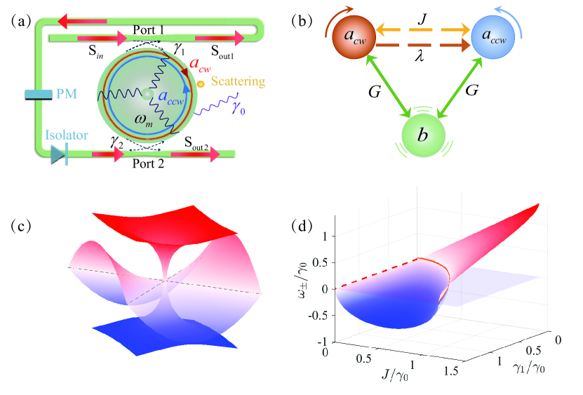
Inspired by a recent experiment, which demonstrates sensitivity enhancement in a non-Hermitian photonic system [79], we consider a non-Hermitian optomechanical system comprising of a WGM microresonator and a tapered fiber, as shown in Fig. 1. Due to manufacturing limitations, the WGM microresonator includes imperfections inevitably, which leads to backscattering of transmitted light. For simplicity, we can attribute these backscattering to the coupling of a nanoparticle. At this point, the two transmitted modes of WGM microresonator, denoted as the clockwise (CW) mode and the counterclockwise (CCW) mode , are coupled to each other with the symmetric coupling strength . To study OMIT in a non-Hermitian optomechanical system, the structure of the fiber is redesigned [74, 79], which results in the asymmetric one-way coupling between the two transmitted modes with effective coupling constant .
In our proposal, the microresonator, with resonance frequency and intrinsic decay rate , supports a mechanical mode with mechanical frequency and damping rate . The optomechanical coupling strength between the mechanical mode and both the optical transmitted modes is denoted as , where is the radius of the microresonator. The system is driven by a strong pump field with frequency and a weak probe field with frequency . The amplitudes of the pump field and probe field are , , where and is the laser power of the pump field and probe field. The Hamiltonian describing the total system can be written as ()
| (1) | ||||
is the asymmetric one-way coupling constant, which is described by . Here, and are the coupling coefficients between the fiber and the microresonator at Port 1 and Port 2, respectively. The displacement and momentum operators of the mechanical oscillator are denoted by and . is the effective mass of the mechanical oscillator. is the transmission coefficient of different transmission light between Port 1 and Port 2 in the redesigned fiber, which is determined by the frequency of the transmission light and the loss coefficient of the fiber.
Since the single photon optomechanical coupling strength is too small, here we consider only the non-Hermitian properties of the optical subsystem [83, 84]. We designate the corresponding eigenvalues of the non-Hermitian system as , which can be derived as
| (2) | |||
| (3) |
where
| (4) | ||||
| (5) |
For simplicity, the symmetric coupling between the two transmitted modes is considered to be a real number [68, 79]. According to the theory of non-Hermitian physics, the eigenvalues of system would coalesce at the phase transition point. Here, and mean that the eigenvalues of system coalesce when the system parameters satisfy a specific relationship. At this time, the surface formed by the parameter relationship is called ES in non-Hermitian physics. For instance, when , meaning the symmetric coupling between the two transmitted modes is nonexistent, the eigenvalues are and , as indicated by the red dashed line in Fig. 1(d). In this article, we mainly study the more general situation, i.e., . When the phase is tuned to , Eqs. (2) and (3) can be simplified as
| (6) | |||
| (7) |
It is easy to observe that when the symmetric coupling satisfied the following relationship
| (8) |
the two eigenvalues of the system are same. And the result is shown in the orange solid line of Fig. 1(d). The point corresponding to the above relationship in Eq. (8) is the so-called phase transition point where the first-order quantum phase transition occurs in the non-Hermitian system. The surface that unfolds in the parameter space according to the relationship is called ES, which is the main research content in this article.
We have pointed out the formation of ES in the studied non-Hermitian system. Next, we will derive the transmission spectrum of the system and study the effect of ES on the transmission spectrum. In the rotating frame with the pump field frequency, , the dynamical quantum Langevin equations of the system can be given by
| (9) |
where , , , and . When the system reaches its steady state, all dynamical variables no longer change with time. Meanwhile, the steady-state values of the dynamical variables can be given by
| (10) |
To study the OMIT in our system, we calculate the optical transmission rate by linearizing the system operators, i.e., expanding the operator as the sum of its steady value and a small fluctuation [35]. Specifically, the system operators are expanded as
| (11) | ||||
| (12) |
Substituting Eqs. (11) and (12) into Eq. (II), we can obtain
| (13) |
where and . The results of and can be calculated by solving Eq. (II). However, as the results are too cumbersome, these results are not shown here. Now, we can derive the output fields at Port 1 and Port 2 using the standard input-output relationships
| (14) |
where and are the input and out field operators, respectively. The transmission coefficient is defined by . Then, the transmission rate is obtained by
| (15) |
In this section, we have discussed the appearance of the ES and derived the transmission spectrum of system. This lays the groundwork for our forthcoming discussion regarding the effects of ES on OMIT spectrum and the group delay.
III Result and discussion
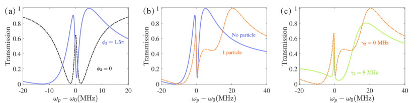
First, we give the selected experimentally feasible parameter values in our proposal, i.e., , , , , , , [85, 68, 67]. To ensure completeness and facilitate comparison, we begin by considering the standard OMIT spectrum, which excludes any particles and unidirectional coupling. Initially, we adjust the phase , which is consistent with the previous analytic result. Subsequently, nanoparticle-induced symmetric backscattering and asymmetric coupling are introduced respectively to stratify the changes of OMIT. These results are shown in Fig. 2. We can observe that the adjustment of the phase of the probe field leads to a complete flip and change in the shape of the OMIT spectrum. When we introduce the external nanoparticle, the resulting spectrum is consistent with the OMIT spectrum generated by an external nanoparticle incorporation [67]. Different from the previous schemes, the introduction of asymmetric coupling results in the non-Hermitian nature of the system, i.e., . At this time, we can study the change of the OMIT spectrum on the ES.
To compare the differences between different EPs on the ES and the distinctions between EPs and NPs, we have selected two different ESs, which are and , as shown in Fig. 3(a). Additionally, we have chosen three EPs to compare the differences within the same or different ESs. Moreover, we have also chosen two NPs to contrast the disparities between NPs and EPs on the OMIT spectrum.
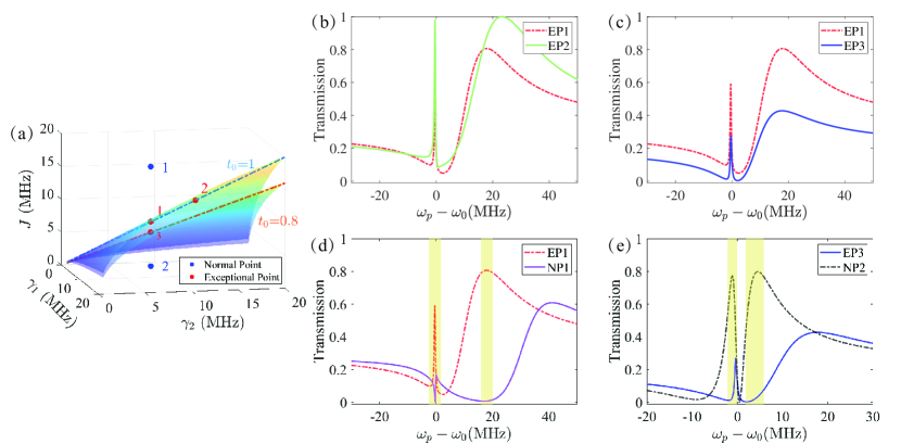
Figure 3 illustrates the variation of transmittance with the detuning of the probe field at the different points. The trends of the OMIT spectrum for the three EPs are similar, where two transparent windows are obtained. The left window is induced by optomechanical coupling, while the right one comes from the coupling between the two transmitted modes. When the system parameters are set at the EP, satisfied the relationship in Eq. (8), the right transparent peak appears, and the results are shown in Figs. 3(b) and (c). On the same ES, we can see that shows higher transmittance compared to , which is attributed to the higher coupling rate facilitating enhanced interaction with the cavity. This intensified interaction leads to more pronounced physical phenomena, resulting in higher transmission at the transparent windows for . Differently, exhibits higher transmittance globally compared to on the other ES due to the smaller transmission rate at . This discrepancy causes partial light absorption within the fiber, independent of the detection field frequency, ultimately lowering the overall transmittance of compared to . Furthermore, we also selected two additional NPs to contrast with EPs. Unlike traditional periodic EPs [67], which feature only a peak-valley conversion pair (a transparent peak turning into an absorption valley), the ES can exhibit more than one conversion pair. Not only can they shift from a transparent peak to an absorption valley, but they can also transition from an absorption valley to a transparent peak [see the highlighted zone in Figs. 3(d) and (e)]. Those results challenge the conventional perception of EPs’ impact on the OMIT spectrum and broadens their properties.
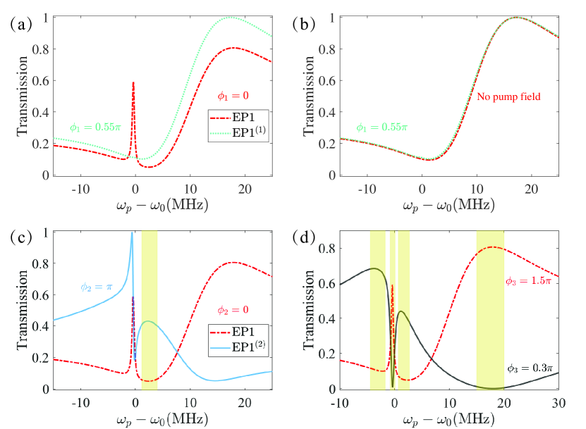
One of the advantages of ES is its wide range of adjustable parameters. In addition to the aforementioned coupling coefficient and transmission rate parameters , there is a more extensive set of parameters available for adjustment, such as phase (. By tuning the phase, we can not only move the system away from or towards the EP, but also generate more derived points of the original EP, such as with different phases [see Fig. 4]. Surprisingly, these derived points of EP not only exhibit similar physical properties as [see Fig. 4(c)], but they can even eliminate the transparency windows caused by optomechanical interaction [see Fig. 4(b)]. For , the left transmission peak disappears [see the blue dotted curve in Fig. 4(a)], which is almost completely overlapped with the transmission spectrum when the pump light is turned off. In other words, manipulating the phase of the pump light allows us to offset the optomechanical interaction influence. That is because the introduction of an extra phase causes the destructive interference between the pump light entering the cavity from Port 1 and that from Port 2. Consequently, this interference prevents the effective delivery of driving power to the cavity. In Fig. 4(d), when we change , the parameter relationship in Eq. (8) will no longer be satisfied, which represents the system is out of ES. Meanwhile, if , the transmission spectrum will be flipped. The original transparency window becomes an absorption valley, while the absorption valley turns into a transmission window, as shown in Fig. 4(d).
We have previously discussed the impact of EP and NP on transmission spectra. There are two methods to shift the system from the EP in the ES to the NP. The first method involves adjusting the coupling strength, e.g., , so that they no longer satisfy the relationship . The second method entails altering the phase , thereby disrupting the effectiveness of the equation in forming an ES. We find that both of these methods can induce a peak-valley conversion pair in the transmission spectrum.
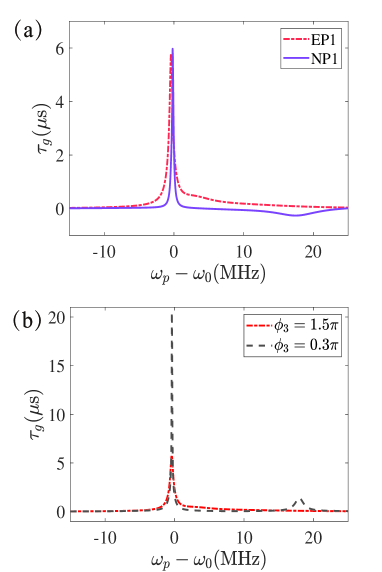
In addition to discussing the effect of ES on the transmission spectra, the phenomenon of group velocity dispersion, i.e., the slow-light effects, is also affected by ES. Here, the optical group delay is characterized by
| (16) |
For the first case (changing the coupling strength), there are two peak-valley conversion pairs for and , as shown in Fig. 3(d). The first peak-valley conversion pair occurs at , where the transmission is converted to absorption when the system changes from to . However, the second peak-valley conversion pair is the opposite, which occurs at . At this time, the fast-slow light effects in both places are also completely different, as shown in Fig 5. We find that both and exhibit slow light behavior for the first peak-valley conversion location, which suggests the formation of slow-fast light is not significantly influenced by the peak-valley conversion in the transmission spectrum at . On the other hand, the fast-slow light effects are opposite for the second peak-valley conversion location when the system changes from to . Finally, we also discuss the influence of phase on the fast-slow light effect and the results are shown in Fig 5(b). We can see that the slow light effect is enhanced at both peak-valley conversion locations when the system changes from EP () to NP ().
IV Experimental feasibility
In this section, the focus is primarily on discussing the feasibility of theoretical models in experiments. The cavity optomechanical system of the WGM type has been extensively studied experimentally [82, 68, 86, 85, 87]. Therefore, the theoretical model consists of two crucial components to be experimentally implemented. The first part involves the coupling between the transmitted modes of WGM and the external nanoparticle. The second part deals with controlling the transmission rate and phase of light. Based on these experimental and theoretical studies [85, 68, 67], we have chosen the feasible parameters according to those WGM experiments. The chosen parameters are , , , , , , throughout the discussions. Next, let’s focus on the key parts of this proposal.
In experiments, the coupling strength between the fiber and the WGM transmitted mode can reach up to tens of MHz at its highest and can be controlled by varying the distance [88, 79], which completely meets the range of our model (changing from to ). The coupling coefficient between the nanoparticle and the WGM transmitted mode depends on the volume of the particle in the WGM evanescent field, which can be controlled by adjusting the size of the particle or their distance [67]. According to those existing experiments [68], can be varied from to , which can be fully achievable in our proposal. The unidirectional coupling can be achieved by adding an isolator at the end of the waveguide in experiments[78, 79, 89]. Furthermore, the phase of light fields can be adjusted by the phase modulator(PM). The transmission coefficient of the waveguide can be changed by changing the waveguide length in actual experiment [79]. Anyway, the experimental parameters and techniques involved in our protocol are fully feasible under the current experimental conditions.
V CONCLUSION
In conclusion, we have proposed a scheme to study the behavior of OMIT on ES in a non-Hermitian WGM-type optomechanical system, where the non-Hermitian nature of the system comes from the ingenious structural design of waveguide. Compared to a single EP, ES is not only able to provide an infinite number of EPs to discuss the effect of phase transition point on the system OMIT, but also is more robust for parameter selection, which is more friendly for experimental design [74, 79]. We respectively study the influence of NP, EP (on the same or different ESs), and the exceptional derived points on the system OMIT. And we find some interesting phenomena in the transmission spectrum of the system, such as peak-valley conversion induced by phase transition and arbitrary manipulation of transmission spectra by using different EPs. Finally, we study the fast-slow light effects of transmission spectroscopy at different exceptional and normal points and find the conversion and enhancement effects of the fast-slow light of the system. Our research can provide theoretical guidance for information transmission in non-Hermitian quantum systems, and it is expected to realize ES-enhanced robust quantum sensing.
Acknowledgements.
This work was supported by the National Natural Science Foundation of China under Grants (No. 12204424, No. 12147149, No. 12147156, No. 12274376, No. 12074346, No. U21A20434, No. 11935006, No. 11774086), the China Postdoctoral Science Foundation (No. 2022M722889), the Natural Science Foundation of Henan Province under Grant (No. 212300410085), the Hunan Provincial Major Sci-Tech Program (Grant No. 2023ZJ1010), and the Science and Technology Innovation Program of Hunan Province (Grant No. 2020RC4047).Appendix A The data of EPs and NPs
| 8 MHz | 8 MHz | 8 MHz | 1 | 0 | 0 | 1.5 | |
| 12 MHz | 12 MHz | 12 MHz | 1 | 0 | 0 | 1.5 | |
| 6.4 MHz | 8 MHz | 8 MHz | 0.8 | 0 | 0 | 1.5 | |
| 16.4 MHz | 8 MHz | 8 MHz | 1 | 0 | 0 | 1.5 | |
| 1.23 MHz | 8 MHz | 8 MHz | 0.8 | 0 | 0 | 1.5 | |
| 8 MHz | 8 MHz | 8 MHz | 1 | 0.55 | 0 | 1.5 | |
| 8 MHz | 8 MHz | 8 MHz | 1 | 0 | 1.5 | ||
| 8 MHz | 8 MHz | 8 MHz | 1 | 0 | 0 | 0.3 |
References
- Metcalfe [2014] M. Metcalfe, Applications of cavity optomechanics, Appl. Phys. Rev. 1, 031105 (2014).
- Bekker et al. [2017] C. Bekker, R. Kalra, C. Baker, and W. P. Bowen, Injection locking of an electro-optomechanical device, Optica 4, 1196 (2017).
- Aspelmeyer et al. [2014] M. Aspelmeyer, T. J. Kippenberg, and F. Marquardt, Cavity optomechanics, Rev. Mod. Phys. 86, 1391 (2014).
- Midolo et al. [2018] L. Midolo, A. Schliesser, and A. Fiore, Nano-opto-electro-mechanical systems, Nat. Nanotechnol 13, 11 (2018).
- Li et al. [2017] J. Li, G. Li, S. Zippilli, D. Vitali, and T. Zhang, Enhanced entanglement of two different mechanical resonators via coherent feedback, Phys. Rev. A 95, 043819 (2017).
- Yan et al. [2019] X.-B. Yan, Z.-J. Deng, X.-D. Tian, and J.-H. Wu, Entanglement optimization of filtered output fields in cavity optomechanics, Opt. Express 27, 24393 (2019).
- Liao et al. [2014] J.-Q. Liao, Q.-Q. Wu, and F. Nori, Entangling two macroscopic mechanical mirrors in a two-cavity optomechanical system, Phys. Rev. A 89, 014302 (2014).
- Stefanatos [2017] D. Stefanatos, Maximising optomechanical entanglement with optimal control, Quantum Sci. Technol. 2, 014003 (2017).
- Deng et al. [2016] Z. J. Deng, X.-B. Yan, Y.-D. Wang, and C.-W. Wu, Optimizing the output-photon entanglement in multimode optomechanical systems, Phys. Rev. A 93, 033842 (2016).
- Vitali et al. [2007] D. Vitali, S. Gigan, A. Ferreira, H. R. Böhm, P. Tombesi, A. Guerreiro, V. Vedral, A. Zeilinger, and M. Aspelmeyer, Optomechanical Entanglement between a Movable Mirror and a Cavity Field, Phys. Rev. Lett. 98, 030405 (2007).
- Liu et al. [2023] J.-X. Liu, Y.-F. Jiao, Y. Li, X.-W. Xu, Q.-Y. He, and H. Jing, Phase-controlled asymmetric optomechanical entanglement against optical backscattering, Sci. China Phys. Mech. Astron. 66, 230312 (2023).
- Meng et al. [2020] C. Meng, G. A. Brawley, J. S. Bennett, M. R. Vanner, and W. P. Bowen, Mechanical Squeezing via Fast Continuous Measurement, Phys. Rev. Lett. 125, 043604 (2020).
- Nation [2013] P. D. Nation, Nonclassical mechanical states in an optomechanical micromaser analog, Phys. Rev. A 88, 053828 (2013).
- Bergholm et al. [2019] V. Bergholm, W. Wieczorek, T. Schulte-Herbrüggen, and M. Keyl, Optimal control of hybrid optomechanical systems for generating non-classical states of mechanical motion, Quantum Sci. Technol. 4, 034001 (2019).
- Ren et al. [2013] X.-X. Ren, H.-K. Li, M.-Y. Yan, Y.-C. Liu, Y.-F. Xiao, and Q. Gong, Single-photon transport and mechanical NOON-state generation in microcavity optomechanics, Phys. Rev. A 87, 033807 (2013).
- Chan et al. [2011] J. Chan, T. P. M. Alegre, A. H. Safavi-Naeini, J. T. Hill, A. Krause, S. Gröblacher, M. Aspelmeyer, and O. Painter, Laser cooling of a nanomechanical oscillator into its quantum ground state, Nature 478, 89 (2011).
- Teufel et al. [2011a] J. D. Teufel, T. Donner, D. Li, J. W. Harlow, M. S. Allman, K. Cicak, A. J. Sirois, J. D. Whittaker, K. W. Lehnert, and R. W. Simmonds, Sideband cooling of micromechanical motion to the quantum ground state, Nature 475, 359 (2011a).
- Xu and Li [2015] X.-W. Xu and Y. Li, Optical nonreciprocity and optomechanical circulator in three-mode optomechanical systems, Phys. Rev. A 91, 053854 (2015).
- He et al. [2018] B. He, L. Yang, X. Jiang, and M. Xiao, Transmission Nonreciprocity in a Mutually Coupled Circulating Structure, Phys. Rev. Lett. 120, 203904 (2018).
- Huang and Agarwal [2009] S. Huang and G. S. Agarwal, Normal-mode splitting in a coupled system of a nanomechanical oscillator and a parametric amplifier cavity, Phys. Rev. A 80, 033807 (2009).
- Gröblacher et al. [2009] S. Gröblacher, K. Hammerer, M. R. Vanner, and M. Aspelmeyer, Observation of strong coupling between a micromechanical resonator and an optical cavity field, Nature 460, 724 (2009).
- Dobrindt et al. [2008] J. M. Dobrindt, I. Wilson-Rae, and T. J. Kippenberg, Parametric Normal-Mode Splitting in Cavity Optomechanics, Phys. Rev. Lett. 101, 263602 (2008).
- Lecocq et al. [2016] F. Lecocq, J. Clark, R. Simmonds, J. Aumentado, and J. Teufel, Mechanically Mediated Microwave Frequency Conversion in the Quantum Regime, Phys. Rev. Lett. 116, 043601 (2016).
- Bagci et al. [2014] T. Bagci, A. Simonsen, S. Schmid, L. G. Villanueva, E. Zeuthen, J. Appel, J. M. Taylor, A. Sørensen, K. Usami, A. Schliesser, and E. S. Polzik, Optical detection of radio waves through a nanomechanical transducer, Nature 507, 81 (2014).
- Wang et al. [2023] Y. Wang, H.-L. Zhang, J.-L. Wu, J. Song, K. Yang, W. Qin, H. Jing, and L.-M. Kuang, Quantum parametric amplification of phonon-mediated magnon-spin interaction, Sci. China Phys. Mech. Astron. 66, 110311 (2023).
- Grudinin et al. [2010] I. S. Grudinin, H. Lee, O. Painter, and K. J. Vahala, Phonon Laser Action in a Tunable Two-Level System, Phys. Rev. Lett. 104, 083901 (2010).
- Jing et al. [2014a] H. Jing, Ş. K. Özdemir, X.-Y. Lü, J. Zhang, L. Yang, and F. Nori, PT -Symmetric Phonon Laser, Phys. Rev. Lett. 113, 053604 (2014a).
- Lei et al. [2016] C. Lei, A. Weinstein, J. Suh, E. Wollman, A. Kronwald, F. Marquardt, A. Clerk, and K. Schwab, Quantum Nondemolition Measurement of a Quantum Squeezed State Beyond the 3 dB Limit, Phys. Rev. Lett. 117, 100801 (2016).
- Gavartin et al. [2012] E. Gavartin, P. Verlot, and T. J. Kippenberg, A hybrid on-chip optomechanical transducer for ultrasensitive force measurements, Nat. Nanotechnol 7, 509 (2012).
- Arcizet et al. [2006] O. Arcizet, P.-F. Cohadon, T. Briant, M. Pinard, A. Heidmann, J.-M. Mackowski, C. Michel, L. Pinard, O. Français, and L. Rousseau, High-Sensitivity Optical Monitoring of a Micromechanical Resonator with a Quantum-Limited Optomechanical Sensor, Phys. Rev. Lett. 97, 133601 (2006).
- Harris [1997] S. E. Harris, Electromagnetically Induced Transparency, Phys Today 50, 36 (1997).
- Harris et al. [1990] S. E. Harris, J. E. Field, and A. Imamoğlu, Nonlinear optical processes using electromagnetically induced transparency, Phys. Rev. Lett. 64, 1107 (1990).
- Boller et al. [1991] K.-J. Boller, A. Imamoğlu, and S. E. Harris, Observation of electromagnetically induced transparency, Phys. Rev. Lett. 66, 2593 (1991).
- Agarwal and Huang [2010] G. S. Agarwal and S. Huang, Electromagnetically induced transparency in mechanical effects of light, Phys. Rev. A 81, 041803 (2010).
- Weis et al. [2010] S. Weis, R. Rivière, S. Deléglise, E. Gavartin, O. Arcizet, A. Schliesser, and T. J. Kippenberg, Optomechanically Induced Transparency, Science 330, 1520 (2010).
- Yan [2020] X.-B. Yan, Optomechanically induced transparency and gain, Phys. Rev. A 101, 043820 (2020).
- Teufel et al. [2011b] J. D. Teufel, D. Li, M. S. Allman, K. Cicak, A. J. Sirois, J. D. Whittaker, and R. W. Simmonds, Circuit cavity electromechanics in the strong-coupling regime, Nature 471, 204 (2011b).
- Zhang et al. [2018a] H. Zhang, F. Saif, Y. Jiao, and H. Jing, Loss-induced transparency in optomechanics, Opt. Express 26, 25199 (2018a).
- Karuza et al. [2013] M. Karuza, C. Biancofiore, M. Bawaj, C. Molinelli, M. Galassi, R. Natali, P. Tombesi, G. Di Giuseppe, and D. Vitali, Optomechanically induced transparency in a membrane-in-the-middle setup at room temperature, Phys. Rev. A 88, 013804 (2013).
- Hill et al. [2012] J. T. Hill, A. H. Safavi-Naeini, J. Chan, and O. Painter, Coherent optical wavelength conversion via cavity optomechanics, Nat. Commun 3, 1196 (2012).
- Agarwal and Huang [2012] G. S. Agarwal and S. Huang, Optomechanical systems as single-photon routers, Phys. Rev. A 85, 021801 (2012).
- Chang et al. [2011] D. E. Chang, A. H. Safavi-Naeini, M. Hafezi, and O. Painter, Slowing and stopping light using an optomechanical crystal array, New J. Phys. 13, 023003 (2011).
- Zhang et al. [2012] J.-Q. Zhang, Y. Li, M. Feng, and Y. Xu, Precision measurement of electrical charge with optomechanically induced transparency, Phys. Rev. A 86, 053806 (2012).
- Safavi-Naeini et al. [2011] A. H. Safavi-Naeini, T. P. M. Alegre, J. Chan, M. Eichenfield, M. Winger, Q. Lin, J. T. Hill, D. E. Chang, and O. Painter, Electromagnetically induced transparency and slow light with optomechanics, Nature 472, 69 (2011).
- Xiong et al. [2017] H. Xiong, Z.-X. Liu, and Y. Wu, Highly sensitive optical sensor for precision measurement of electrical charges based on optomechanically induced difference-sideband generation, Opt. Lett. 42, 3630 (2017).
- Wen et al. [2022] P. Wen, M. Wang, and G.-L. Long, Optomechanically induced transparency and directional amplification in a non-hermitian optomechanical lattice, Opt. Express 30, 41012 (2022).
- Zhang et al. [2018b] X. Zhang, Y. Zhou, Y. Guo, and X. Yi, Double optomechanically induced transparency and absorption in parity-time-symmetric optomechanical systems, Phys. Rev. A 98, 033832 (2018b).
- Xiong et al. [2022] W. Xiong, Z. Li, G.-Q. Zhang, M. Wang, H.-C. Li, X.-Q. Luo, and J. Chen, Higher-order exceptional point in a blue-detuned non-hermitian cavity optomechanical system, Phys. Rev. A 106, 033518 (2022).
- Wang et al. [2019a] B. Wang, Z.-X. Liu, C. Kong, H. Xiong, and Y. Wu, Mechanical exceptional-point-induced transparency and slow light, Opt. Express 27, 8069 (2019a).
- Özdemir et al. [2019] Ş. K. Özdemir, S. Rotter, F. Nori, and L. Yang, Parity–time symmetry and exceptional points in photonics, Nat. Mater. 18, 783 (2019).
- Feng et al. [2017] L. Feng, R. El-Ganainy, and L. Ge, Non-Hermitian photonics based on parity–time symmetry, Nat. Photonics 11, 752 (2017).
- Miri and Alù [2019] M.-A. Miri and A. Alù, Exceptional points in optics and photonics, Science 363, eaar7709 (2019).
- El-Ganainy et al. [2018] R. El-Ganainy, K. G. Makris, M. Khajavikhan, Z. H. Musslimani, S. Rotter, and D. N. Christodoulides, Non-Hermitian physics and PT symmetry, Nat. Phys 14, 11 (2018).
- Xu et al. [2023] X.-W. Xu, J.-Q. Liao, H. Jing, and L.-M. Kuang, Anti-parity-time symmetry hidden in a damping linear resonator, SCI CHINA PHYS MECH 66, 100312 (2023).
- Zhong et al. [2020] Q. Zhong, S. Ozdemir, A. Eisfeld, A. Metelmann, and R. El-Ganainy, Exceptional-point-based optical amplifiers, Phys. Rev. Appl. 13, 014070 (2020).
- Guo et al. [2009] A. Guo, G. J. Salamo, D. Duchesne, R. Morandotti, M. Volatier-Ravat, V. Aimez, G. A. Siviloglou, and D. N. Christodoulides, Observation of P T -Symmetry Breaking in Complex Optical Potentials, Phys. Rev. Lett. 103, 093902 (2009).
- Longhi and Feng [2017] S. Longhi and L. Feng, Unidirectional lasing in semiconductor microring lasers at an exceptional point [Invited], Photon. Res. 5, B1 (2017).
- Lin et al. [2011] Z. Lin, H. Ramezani, T. Eichelkraut, T. Kottos, H. Cao, and D. N. Christodoulides, Unidirectional Invisibility Induced by P T -Symmetric Periodic Structures, Phys. Rev. Lett. 106, 213901 (2011).
- Heiss and Sannino [1990] W. Heiss and A. Sannino, Avoided level crossing and exceptional points, J. Phys. A Math. Theor. 23, 1167 (1990).
- Magunov et al. [1999] A. Magunov, I. Rotter, and S. Strakhova, Laser-induced resonance trapping in atoms, J PHYS B-AT MOL OPT 32, 1669 (1999).
- Heiss [2004] W. Heiss, Exceptional points of non-hermitian operators, J. Phys. A Math. Theor. 37, 2455 (2004).
- Heiss [2012] W. Heiss, The physics of exceptional points, J. Phys. A Math. Theor. 45, 444016 (2012).
- Assawaworrarit et al. [2017] S. Assawaworrarit, X. Yu, and S. Fan, Robust wireless power transfer using a nonlinear parity–time-symmetric circuit, Nature 546, 387 (2017).
- Peng et al. [2014a] B. Peng, Ş. K. Özdemir, S. Rotter, H. Yilmaz, M. Liertzer, F. Monifi, C. M. Bender, F. Nori, and L. Yang, Loss-induced suppression and revival of lasing, Science 346, 328 (2014a).
- Zhou et al. [2018] H. Zhou, C. Peng, Y. Yoon, C. W. Hsu, K. A. Nelson, L. Fu, J. D. Joannopoulos, M. Soljačić, and B. Zhen, Observation of bulk Fermi arc and polarization half charge from paired exceptional points, Science 359, 1009 (2018).
- Yang et al. [2018] B. Yang, Q. Guo, B. Tremain, R. Liu, L. E. Barr, Q. Yan, W. Gao, H. Liu, Y. Xiang, J. Chen, C. Fang, A. Hibbins, L. Lu, and S. Zhang, Ideal Weyl points and helicoid surface states in artificial photonic crystal structures, Science 359, 1013 (2018).
- Lü et al. [2018] H. Lü, C. Wang, L. Yang, and H. Jing, Optomechanically Induced Transparency at Exceptional Points, Phys. Rev. Applied 10, 014006 (2018).
- Chen et al. [2017] W. Chen, Ş. K. Özdemir, G. Zhao, J. Wiersig, and L. Yang, Exceptional points enhance sensing in an optical microcavity, Nature 548, 192 (2017).
- Zhang et al. [2022] J.-Q. Zhang, J.-X. Liu, H.-L. Zhang, Z.-R. Gong, S. Zhang, L.-L. Yan, S.-L. Su, H. Jing, and M. Feng, Topological optomechanical amplifier in synthetic pt-symmetry, Nanophotonics 11, 1149 (2022).
- Jing et al. [2014b] H. Jing, S. K. Özdemir, X.-Y. Lü, J. Zhang, L. Yang, and F. Nori, -symmetric phonon laser, Phys. Rev. Lett. 113, 053604 (2014b).
- Xu et al. [2015] X.-W. Xu, Y.-x. Liu, C.-P. Sun, and Y. Li, Mechanical symmetry in coupled optomechanical systems, Phys. Rev. A 92, 013852 (2015).
- Wang et al. [2019b] D.-Y. Wang, C.-H. Bai, S. Liu, S. Zhang, and H.-F. Wang, Distinguishing photon blockade in a -symmetric optomechanical system, Phys. Rev. A 99, 043818 (2019b).
- Hodaei et al. [2017] H. Hodaei, A. U. Hassan, S. Wittek, H. Garcia-Gracia, R. El-Ganainy, and M. Christodoulides, Demetrios N a nd Khajavikhan, Enhanced sensitivity at higher-order exceptional points, Nature 548, 187 (2017).
- Zhong et al. [2019] Q. Zhong, J. Ren, M. Khajavikhan, D. Christodoulides, Ş. K. Özdemir, and R. El-Ganainy, Sensing with Exceptional Surfaces in Order to Combine Sensitivity with Robustness, Phys. Rev. Lett. 122, 153902 (2019).
- Zhou et al. [2019] H. Zhou, J. Y. Lee, S. Liu, and B. Zhen, Exceptional surfaces in pt-symmetric non-hermitian photonic systems, Optica 6, 190 (2019).
- Chen et al. [2022] L. Chen, W. Wu, F. Huang, Y. Chen, G.-S. Liu, Y. Luo, and Z. Chen, Chaotic dynamics on exceptional surfaces, Phys. Rev. A 105, L031501 (2022).
- Yang et al. [2021] H. Yang, X. Mao, G.-Q. Qin, M. Wang, H. Zhang, D. Ruan, and G.-L. Long, Scalable higher-order exceptional surface with passive resonators, Opt. Lett. 46, 4025 (2021).
- Jiang et al. [2023] S. Jiang, J. Li, Z. Li, Z. Li, W. Li, X. Huang, H. Zhang, G. Zhang, A. Huang, and Z. Xiao, Experimental realization of exceptional surfaces enhanced displacement sensing with robustness, Appl. Phys. Lett. 123, 201106 (2023).
- Qin et al. [2021] G. Qin, R. Xie, H. Zhang, Y. Hu, M. Wang, G. Li, H. Xu, F. Lei, D. Ruan, and G. Long, Experimental Realization of Sensitivity Enhancement and Suppression with Exceptional Surfaces, Laser Photonics Rev. 15, 2000569 (2021).
- Zhang et al. [2019] X. Zhang, K. Ding, X. Zhou, J. Xu, and D. Jin, Experimental Observation of an Exceptional Surface in Synthetic Dimensions with Magnon Polaritons, Phys. Rev. Lett. 123, 237202 (2019).
- Budich et al. [2019] J. C. Budich, J. Carlström, F. K. Kunst, and E. J. Bergholtz, Symmetry-protected nodal phases in non-hermitian systems, Phys. Rev. B 99, 041406 (2019).
- Peng et al. [2016] B. Peng, Ş. K. Özdemir, M. Liertzer, W. Chen, J. Kramer, H. Yılmaz, J. Wiersig, S. Rotter, and L. Yang, Chiral modes and directional lasing at exceptional points, Proc. Natl. Acad. Sci. U.S.A. 113, 6845 (2016).
- Peng et al. [2023] M. Peng, H. Zhang, Q. Zhang, T.-X. Lu, I. M. Mirza, and H. Jing, Nonreciprocal slow or fast light in anti--symmetric optomechanics, Phys. Rev. A 107, 033507 (2023).
- Djorwe et al. [2019] P. Djorwe, Y. Pennec, and B. Djafari-Rouhani, Exceptional point enhances sensitivity of optomechanical mass sensors, Phys. Rev. Appl. 12, 024002 (2019).
- Peng et al. [2014b] B. Peng, Ş. K. Özdemir, F. Lei, F. Monifi, M. Gianfreda, G. L. Long, S. Fan, F. Nori, C. M. Bender, and L. Yang, Parity–time-symmetric whispering-gallery microcavities, Nat. Phys 10, 394 (2014b).
- He et al. [2011] L. He, Ş. K. Özdemir, J. Zhu, W. Kim, and L. Yang, Detecting single viruses and nanoparticles using whispering gallery microlasers, Nat. Nanotechnol. 6, 428 (2011).
- Özdemir et al. [2014] Ş. K. Özdemir, J. Zhu, X. Yang, B. Peng, H. Yilmaz, L. He, F. Monifi, S. H. Huang, G. L. Long, and L. Yang, Highly sensitive detection of nanoparticles with a self-referenced and self-heterodyned whispering-gallery raman microlaser, Proceedings of the National Academy of Sciences 111, E3836 (2014).
- Maayani et al. [2018] S. Maayani, R. Dahan, Y. Kligerman, E. Moses, A. U. Hassan, H. Jing, F. Nori, D. N. Christodoulides, and T. Carmon, Flying couplers above spinning resonators generate irreversible refraction, Nature 558, 569 (2018).
- Soleymani et al. [2022] S. Soleymani, Q. Zhong, M. Mokim, S. Rotter, R. El-Ganainy, and Ş. Özdemir, Chiral and degenerate perfect absorption on exceptional surfaces, Nat. Commun. 13, 599 (2022).