SNR Maximization and Localization for UAV-IRS-Assisted Near-Field Systems
Abstract
This letter introduces a novel unmanned aerial vehicle (UAV)-intelligent reflecting surface (IRS) structure into near-field localization systems to enhance the design flexibility of IRS, thereby obtaining additional performance gains. Specifically, a UAV-IRS is utilized to improve the harsh wireless environment and provide localization possibilities. To improve the localization accuracy, a joint optimization problem considering UAV position and UAV-IRS passive beamforming is formulated to maximize the receiving signal-to-noise ratio (SNR). An alternative optimization algorithm is proposed to solve the complex non-convex problem leveraging the projected gradient ascent (PGA) algorithm and the principle of minimizing the phase difference of the receiving signals. Closed-form expressions for UAV-IRS phase shift are derived to reduce the algorithm complexity. In the simulations, the proposed algorithm is compared with three different schemes and outperforms the others in both receiving SNR and localization accuracy.
Index Terms:
Near-field localization, unmanned aerial vehicle position optimization, intelligent reflecting surface, passive beamforming.I Introduction
With the development of the fifth generation mobile networks (5G) and its empowering applications across various industry progresses, emerging services such as mobile Internet of things (IoT) and artificial intelligence (AI) continually arise. As a result, there is an increasing demand for centimeter-level localization accuracy on the sixth generation mobile networks (6G) [1, 2, 3]. Although traditional global navigation satellite systems (GNSSs) have provided localization services with broad coverage and massive connectivity [4], their precision falls short of future requirements. In addition, they fail to deliver stable, high-quality services in environments like urban canyons. Recently, wireless communication signals-assisted localization has surged to tackle such GNSS-denied issues and achieve higher localization accuracy. For instance, Shahmansoori et al. [5] proposed a two-stage algorithm based on multiple measurement vectors matching pursuit and space-alternating generalized expectation maximization algorithm. Nazari et al. [6] used downlink multiple-input multiple-output (MIMO) orthogonal frequency-division multiplexing (OFDM) signals to estimate an unsynchronized multi-antenna user equipment’s (UE’s) three-dimensional (3D) position and 3D orientation. However, signals can still be obstructed by physical barriers in certain circumstances, i.e., the line-of-sight (LoS) path is blocked. Under this condition, achieving high-precision localization becomes nearly impossible.
To tackle this issue, the intelligent reflecting surface (IRS) [7, 8, 9] has been integrated into communication-aided localization systems. An IRS is a passive reflecting device composed of multiple reflecting elements. Localization can be realized with the help of virtual LoS (VLoS) paths provided by IRS even when the LoS path is blocked and can be improved via the passive beamforming process. In this process, the phase shift for each reflecting element is designed, and the wireless channels can be manipulated. For example, Dardari et al. [10] proposed two practical signaling and localization algorithms based on OFDM downlink systems, as well as methods to design the IRS time-varying reflection coefficients. Zhang et al. [11] developed a joint estimation algorithm considering UE position and realistic impairments in OFDM systems and proposed a semidefinite relaxation (SDR)-based IRS phase shift optimization algorithm to enhance localization performance.
To realize greater design flexibility of IRS for the further enhancement of wireless environments, a novel unmanned aerial vehicle (UAV)-IRS architecture has recently gained attention. This architecture features a UAV equipped with an IRS. The UAV position and UAV-IRS phase shift can both be controlled by the base station (BS) through a signaling channel. For instance, Wei et al. [12] analyzed the average error probability in UAV-IRS-assisted short packet communication systems. Wang et al. [13] proposed a UAV-IRS-aided covert communication scheme to maximize the covert communication rate. However, current research about UAV-IRS mainly focuses on its enhancement to communication systems, and to the best of the authors’ knowledge, there’s no research considering UAV-IRS-assisted localization systems. To fill this gap, the main contributions of this letter are summarized below:
-
•
We introduce a novel UAV-IRS-assisted near-field localization model, where maximum likelihood estimation (MLE) algorithm is adopted to realize high-precision position estimation. To further improve the localization accuracy, an optimization problem for UAV position and UAV-IRS phase shift is formulated, which maximizes the receiving signal-to-noise ratio (SNR).
-
•
We design an alternative algorithm to solve the non-convex SNR maximization problem. A projected gradient ascent(PGA)-based method is used to update the UAV position. Closed-form expressions for UAV-IRS phase shift are derived to minimize the phase difference of the received signals, significantly reducing the algorithm complexity.
-
•
We conduct simulations comparing our proposed optimization algorithm with three other design schemes. Extensive results demonstrate the effectiveness of our algorithm and the performance improvement in near-field localization.
Notations: denotes the probability density function (PDF). and denote the transpose and conjugate of matrix , respectively. denotes the th entry of vector , while denotes the value of in the th iteration. denotes an sized identity matrix. denotes matrices with complex entries. , and represent calculating 2-norm, modulus and argument, respectively. Finally, represents complex Gaussian distributions with a mean vector of and a covariance matrix of .
II System Model and Problem Formulation
II-A Signal Model
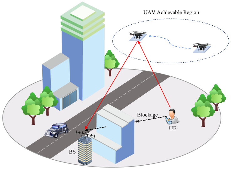
As illustrated in Fig. 1, the considered UAV-IRS-assisted localization system is composed of a single-antenna UE, a UAV-IRS equipped with reflecting elements, and a BS equipped with receiving antennas. The LoS path between UE and BS is blocked, thus only the VLoS path provided by UAV-IRS can be utilized to carry out localization. Both UAV-IRS elements and BS antennas are arranged in uniform linear arrays (ULAs) with element/antenna spacing of , where denotes the wavelength. Although ULAs are considered in this letter, it’s worth noting that the proposed algorithms can be directly extended to uniform planar arrays (UPAs). The UE is assumed to be static or moving slowly, and the UAV-IRS can move in a certain region to further improve the path quality and localization accuracy.
In our work, the positions of the BS and UAV-IRS are assumed to be known, whose reference point coordinates can be denoted as and , respectively, and the coordinate of their antennas/elements can be expressed by and , respectively, where and . The position of UE is assumed to be unknown and is the parameter to be estimated.
One single symbol is utilized in the localization process in this paper and the received signal at BS can be expressed as:
| (1) |
where is the transmit power, is the additive Gaussian noise at BS, and is the UE-IRS-BS channel, modeled as:
| (2) |
where is the Rician factor, and are LoS and Non LoS (NLoS) parts of the channel, respectively. Each term of is given by:
| (3) |
where and are the free-space path losses between UE and UAV-IRS, and between UAV-IRS and BS, respectively, with and being the antenna gains at UE and BS. is the phase shift of the th element of the UAV-IRS. represents the distance between the th element of UAV-IRS and the th antenna of BS, while represents the distance between UE and the th element of UAV-IRS.
Combining the Gaussian distributed NLoS portion of with noise , the received signal can be rewritten as:
| (4) |
where the combined noise can be represented as:
| (5) |
and follows the distribution .
II-B UAV-IRS-Assisted Localization Problem
According to (4), the received signal can be statistically characterized as:
| (6) |
hence, according to the MLE criteria, the UE position can be estimated by minimizing the following negative log-likelihood function:
| (7) |
Then, the estimate of UE position can be given by:
| (8) |
Remark 1: According to (3), the parameters to be estimated appear in the exponent, and there is a large coefficient before the parameters because of the high carrier frequency. This leads to severe oscillations of the likelihood function with respect to the position parameters, resulting in numerous local minima. Therefore, all gradient-based methods, such as gradient descent and Newton’s method, are inapplicable here. We employ the simplest grid search method to solve (8) thereby providing an estimate of the position parameters.
II-C SNR Maximization Problem
To improve the localization accuracy, we formulate an optimization problem for the UAV position and UAV-IRS phase shift . Receiving SNR is considered the objective function here, which is commonly used in existing localization works [14, 15]. According to the signal model (4), the receiving SNR at BS can be expressed by:
| (9) |
which depends on both and . The SNR maximization problem can be formulated as:
| (10) | ||||
| (10a) | ||||
| (10b) |
where (10a) is the unit modulus constraint for UAV-IRS, and constraint (10b) is to guarantee the UAV can only move in a circular achievable region centered at with radius . However, problem (10) is difficult to solve due to the non-convex objective function as well as constraint (10a) and coupled variables. The proposed solution to this problem will be given in the next section.
Integrating the two problems above, the complete localization process contains three steps. Firstly, a rough estimation of the UE position is obtained through MLE using the initial UAV position and random UAV-IRS phase shift. Secondly, the SNR maximization problem is solved based on the estimation result, and a better UAV position and UAV-IRS phase shift can be obtained. Both parameters are transmitted to the UAV via a reliable signaling channel. After the UAV reaches the designed position and configures the phase shift, UE transmits another sensing signal. Thirdly, the MLE is executed again at BS to obtain a more accurate UE position estimate.
III Proposed SNR Maximization Algorithm
This section is devoted to solving the problem (10) by developing a novel alternative optimization approach to optimize UAV position and UAV-IRS phase shift . First, with fixed , we optimize by proposing a PGA-based algorithm. Then, with fixed , we optimize by converting the origin non-convex problem to a phase difference minimization problem. We derive closed-form expressions for the optimal phase shift, thus decreasing the algorithm complexity significantly. Finally, we provide the overall optimization algorithm.
III-A Optimization of with Fixed
Considering initially given or calculated in the past iteration round, we optimize the position of UAV by solving the following subproblem:
| (11) |
which is non-convex because of the complex expression of SNR. We utilize the PGA algorithm to iteratively solve a better UAV position and obtain a higher SNR. In the th iteration round, can be obtained by calculating:
| (12) |
where represents the update step, and represents the projection operator, which can project parameters exceeding the feasible zone back into it. For any given position , can be obtained via solving:
| (13) |
which is convex, and can be directly solved using convex optimization solvers, such as CVX [16].
Take for example, can be calculated as follows:
| (14) |
where
| (15) |
and , with
| (16) |
The partial derivatives of with respect to and can be similarly derived, and will not be further elaborated here.
III-B Optimization of with Fixed
Then, considering given , we optimize the phase shift of UAV-IRS by solving the following subproblem:
| (17) |
which is also non-convex due to the unit-module constraint. To tackle this problem, inspired by [17], by defining , we transfer (III-B) to minimizing the sum of the square distance of the phases from their related centroid by:
| (18) |
which is a convex function, and is given by:
| (19) |
For certain , can be re-expressed by:
| (20) |
and by operating:
| (21) |
the optimal solution can be solved in a closed form:
| (22) |
Thus, the optimal UAV-IRS phase shift can be represented as:
| (23) |
In this way, signals reflected by different elements on UAV-IRS can arrive at BS with the minimum phase difference, thereby achieving higher receiving SNR.
III-C Overall Algorithm
The above analysis of SNR assumes the known UE’s position. In practice, the estimate of UE position is used instead. Thus, we define a new function to replace the calculation of in the following algorithm. Note that the only difference between and is the value substituted.
The overall optimization algorithm is detailed in Algorithm 1, which can be summarized as follows. First, we initialize the parameters including the random UAV-IRS phase shift , initial UAV position , step length for the gradient ascent algorithm, and convergence accuracy for outer/inner loop, /, which should vary with changes in transmit power. Then, taking a rough estimation of UE as input, we start to optimize and alternately, where is optimized using PGA-based algorithm with convergence accuracy , and is optimized using the proposed centroid-based method. is considered to be fixed when optimizing , and vice versa. Finally, after the change of SNR is below the pre-set threshold , the algorithm ends and outputs the optimal UAV position and UAV-IRS phase shift .
IV Simulation Results
This section presents the simulation results conducted to assess the performance of the proposed optimization algorithm and its improvement to UE localization. We consider a 3D Cartesian coordinate system with its reference point located at . The positions of the BS and UE are and in meters, respectively. The initial position of UAV is in meter. The combined noise power is ; the carrier frequency is , light speed is , and the wavelength can be calculated by ; the Rician factor is ; antennas and reflecting elements are equipped on BS and UAV-IRS, respectively, and the antenna gains for UE and BS are . The maximum moving radius of the UAV is set as . Without loss of generality, we assume the UAV always moves in the plane , and the UE is always located in the plane . The grid search method used to solve (8) searches within a square zone centered at the true position of UE, and uses grids.
For the evaluation of the proposed localization and optimization algorithms, we utilize the most commonly used root mean square error (RMSE) and average SNR as metrics, which can be respectively expressed as:
| (24a) | ||||
| (24b) | ||||
where realizations are conducted in the simulations, represents the estimate of UE position in the th trail, and denote the optimal UAV position and UAV-IRS phase shift obtained in the th trail, respectively.
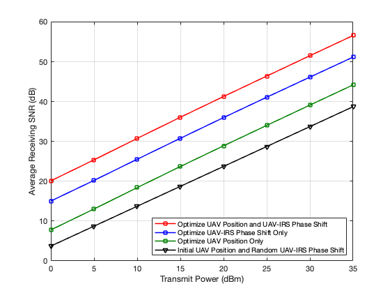
Fig. 2 compares the average receiving SNR under 4 different UAV position and UAV-IRS design schemes, including (a) the proposed joint optimization algorithm; (b) optimizing UAV-IRS phase shift only; (c) optimizing UAV position only and (d) using the initial UAV position and random UAV-IRS phase shift, where the optimization algorithms for schemes (b) and (c) are introduced in III-A and III-B, respectively. It can be observed that the average receiving SNR under all those schemes increases with transmit power. Scheme (d) results in the lowest receiving SNR because of the lack of configuration to the environment. Scheme (c) sees a slight improvement because the SNR function oscillates with the UAV position for a similar reason explained in Remark 1, hence the PGA algorithm-based scheme can only find a local optimal value. Scheme (c) improves SNR more than scheme (b) and thus indicates that the UAV-IRS phase shift optimization algorithm outperforms the UAV position optimization algorithm. Finally, our proposed algorithm, which integrates both schemes (b) and (c), and iterates till convergence, achieves the best performance in improving the receiving SNR at BS.
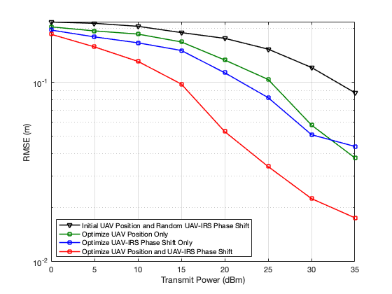
Fig. 3 depicts the RMSE of UE position estimation under the same 4 schemes mentioned above. It’s worth noting that the optimization process of schemes (a), (b), and (c) are based on the estimation result using scheme (d). RMSE under all schemes decreases with transmit power. The magnitude relationship of RMSE curves is almost opposite to the SNR curves, evidencing the effectiveness of maximizing receiving SNR. It’s also observed that schemes (b) and (c) improve RMSE slightly, and perform similarly under the RMSE metric, while our proposed scheme (a) increases the localization accuracy significantly to nearly .
V Conclusion
In this letter, we have introduced a novel UAV-IRS-assisted near-field localization system, where the UAV position can be manipulated, enhancing flexibility in configuring wireless environments and improving localization accuracy. To maximize the receiving SNR, an alternative algorithm is proposed, where the PGA algorithm is utilized to update the UAV position, and a centroid-based method is leveraged to derive closed-form expressions for UAV-RIS phase shift. Extensive simulation results indicate the effectiveness of the optimization algorithm, and the UE localization accuracy has been significantly improved to nearly under a transmit power of .
References
- [1] A. Bourdoux, A. N. Barreto, B. van Liempd, C. de Lima, D. Dardari, D. Belot, E.-S. Lohan, G. Seco-Granados, H. Sarieddeen, H. Wymeersch et al., “6G white paper on localization and sensing,” arXiv preprint arXiv:2006.01779, 2020.
- [2] S. Dang, O. Amin, B. Shihada, and M.-S. Alouini, “What should 6G be?” Nature Electronics, vol. 3, no. 1, pp. 20–29, 2020.
- [3] K. B. Letaief, W. Chen, Y. Shi et al., “The roadmap to 6G: AI empowered wireless networks,” IEEE communications magazine, vol. 57, no. 8, pp. 84–90, 2019.
- [4] E. D. Kaplan and C. Hegarty, Understanding GPS/GNSS: principles and applications. Artech house, 2017.
- [5] A. Shahmansoori, G. E. Garcia, G. Destino, G. Seco-Granados, and H. Wymeersch, “Position and orientation estimation through millimeter-wave MIMO in 5G systems,” IEEE Transactions on Wireless Communications, vol. 17, no. 3, pp. 1822–1835, 2017.
- [6] M. A. Nazari, G. Seco-Granados, P. Johannisson, and H. Wymeersch, “Mmwave 6D radio localization with a snapshot observation from a single BS,” IEEE Transactions on Vehicular Technology, 2023.
- [7] Q. Wu, S. Zhang, B. Zheng, C. You, and R. Zhang, “Intelligent reflecting surface-aided wireless communications: A tutorial,” IEEE transactions on communications, vol. 69, no. 5, pp. 3313–3351, 2021.
- [8] X. Yuan, Y.-J. A. Zhang, Y. Shi, W. Yan, and H. Liu, “Reconfigurable-intelligent-surface empowered wireless communications: Challenges and opportunities,” IEEE wireless communications, vol. 28, no. 2, pp. 136–143, 2021.
- [9] Q. Wu and R. Zhang, “Towards smart and reconfigurable environment: Intelligent reflecting surface aided wireless network,” IEEE communications magazine, vol. 58, no. 1, pp. 106–112, 2019.
- [10] D. Dardari, N. Decarli, A. Guerra, and F. Guidi, “LOS/NLOS near-field localization with a large reconfigurable intelligent surface,” IEEE Transactions on Wireless Communications, vol. 21, no. 6, pp. 4282–4294, 2021.
- [11] H. Zhang, E. Liu, R. Wang, Z. Xing, and Y. Liu, “Near-field localization and phase shift optimization for RIS-assisted non-ideal OFDM systems,” arXiv preprint arXiv:2312.12534, 2023.
- [12] L. Wei, K. Wang, C. Pan, and M. Elkashlan, “Average error probability for UAV-RIS enabled short packet communications,” IEEE Transactions on Vehicular Technology, 2023.
- [13] C. Wang, X. Chen, J. An, Z. Xiong, C. Xing, N. Zhao, and D. Niyato, “Covert communication assisted by UAV-IRS,” IEEE Transactions on Communications, vol. 71, no. 1, pp. 357–369, 2022.
- [14] R. Wang, Z. Xing, E. Liu, and J. Wu, “Joint localization and communication study for intelligent reflecting surface aided wireless communication system,” IEEE Transactions on Communications, 2023.
- [15] R. Liu, M. Li, Y. Liu, Q. Wu, and Q. Liu, “Joint transmit waveform and passive beamforming design for RIS-aided DFRC systems,” IEEE Journal of Selected Topics in Signal Processing, vol. 16, no. 5, pp. 995–1010, 2022.
- [16] M. Grant and S. Boyd, “CVX: Matlab software for disciplined convex programming, version 2.1,” 2014.
- [17] A. Elzanaty, A. Guerra, F. Guidi, and M.-S. Alouini, “Reconfigurable intelligent surfaces for localization: Position and orientation error bounds,” IEEE Transactions on Signal Processing, vol. 69, pp. 5386–5402, 2021.