Selective linewidth control in a micro-resonator
with a resonant interferometric coupler
Abstract
Optical microresonators are characterized by a comb of resonances that preserve similar characteristics over a broad spectral interval. However, for many applications it is beneficial to selectively control of the quality factor (Q) of one or only some resonances.
In this work we propose and experimentally validate the use of a resonant interferometric coupler to selectively change the Q-factor of a target resonance in an integrated silicon nitride microresonator. We show that its Q-factor can be continuously tuned from to , leaving the untargeted resonances uperturbed. Our design can be scaled to independently control several resonances.
I Introduction
Integrated optical microresonators are versatile devices which find use in several applications, such as spectral filters, switches [1, 2, 3, 4], delay lines [5, 6], sensors [7, 8], modulators [9, 10] and light sources [11]. Microresonators are typically characterized by a comb of resonances that preserve similar characteristics, such as the quality factor or the extinction rate, over a broad spectral interval. This feature is harnessed to generate broadband frequency combs [12], soliton pulses [13], or photon pairs in high dimensional entangled states [14]. However, some applications may require the selective and dynamic control of the quality factor () of only some of the resonances. Examples include -switched lasers [15, 16], single frequency lasers [17], tunable modulators [18], tunable delay lines [19], optical memories [20], pseudo-random binary sequence generators [21] and photon pair sources with tailored spectral correlations [22] or high heralding efficiency [23, 24]. Several approaches have been investigated to control the Q-factor [25, 26, 27, 18, 28, 20, 17, 29, 24, 20, 17, 29, 30], and some of them are wavelength selective [25, 26, 24, 20, 17, 29, 30]. For example, a strong control pulse has been used to induce Raman scattering in silicon on a target resonance [25]. However, this operation can be done efficiently only at the maximum of the Raman gain of the material, and demands strict fabrication tolerances [26, 25]. The Q-factor can also be tuned by varying the phase shift in an unbalanced interferometer forming the coupling region of a microresonator [18, 28]. Alternatively, the Q-factor of a single resonance can be changed due to the strong coupling with another resonator [20, 17, 29, 30].
or by a combination of the previous strategies [24].
In this work, we propose and experimentally demonstrate the selective control of the Q-factor of a single resonance in a microresonator by using a resonant interferometric coupler. A Main resonator is coupled twice to a bus waveguide to form an unbalanced Mach-Zehnder interferometer (MZI). Then, we introduce an auxiliary resonator (Aux) in one of the arms to impart a wavelength-selective phase. This changes the interference within the MZI and thus the effective coupling coefficient with the input waveguide. The article is structured as follows: in Sec.II we describe the working principle of the device and explore different configurations which allows us to selectively change the Q-factor of a target resonance. The device is then fabricated on a silicon nitride chip, and its experimental characterization is reported in Sec.III. Here we show that the Q-factor of the target resonance can be continuously changed from to with minimal perturbation of the adjacent ones.
II Working principle of the device
The proposed structure is sketched in Fig.1. A main ring resonator (Main) of radius is coupled twice to a bus-waveguide at points A and B, with coupling coefficients and respectively, to form an interferometric coupler [18]. An auxiliary resonator of radius is also coupled to the bus waveguide at point C.
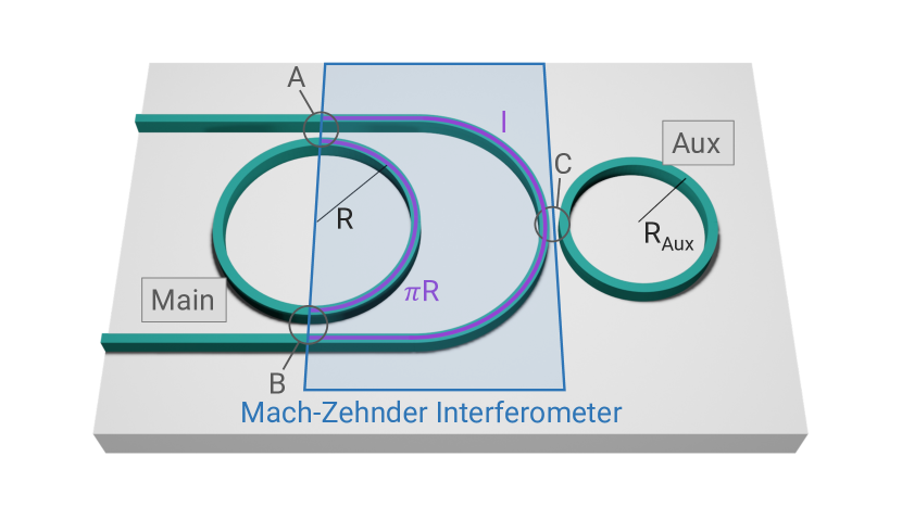
The highlighted area in Fig.1 can be seen as a Mach-Zehnder interferometer (MZI), with a first arm of length along the Main ring, and a second arm of length along the bus-waveguide.
The effective coupling of the Main ring resonator to the bus waveguide depends on the phase difference between the two MZI arms [18, 28, 31]. Such a difference is given by two distinct contributions: the imbalance in the optical length of the two interferometer arms, and the transmission of the Aux ring. The former contribution acts at all frequencies, the latter is relevant only when its frequency is within the spectral width of an Aux ring resonance. Thus, one has two sets of resonances that can be controlled independently: those that belong only to the Main ring and those that are shared with the Aux. For instance, by choosing incommensurate values for and , it is possible to selectively control one single resonance. Using a microheater, one can adjust the refractive index of the bus waveguide to set the desired coupling for all the other Main resonances. An additional microheater can act on the Aux to align one of its resonances to the target Main ring resonance.
With reference to Fig.1, the device transmission at the output port can be written as
| (1) |
where and are the self- and cross-coupling coefficients at point , and is the complex wavevector, which accounts for both propagation () and linear attenuation (). Finally,
| (2) |
describes the attenuation and phase difference acquired between the two arms of the MZI, and
| (3) |
is the transmission amplitude of the Aux resonator, with .
Unsurprisingly, Eq.(1) is equivalent to the transmission of a resonator in the all-pass filter configuration in which the effective coupling coefficient with the input waveguide is given by
| (4) |
which is the expression for the cross port transmission of the MZI, where .
We now consider the special case in which . Thus, for all of the resonances that are spectrally far from those of the Aux (for which and arg) we have that the phase difference in the MZI is a multiple of , and the interference is constructive at the cross port of the MZI. In this situation, when , the effective coupling is maximum and equal to . Changing through a micro-heater placed in the long arm of the MZI modifies for all the resonances. However, if the Aux resonator is used to change the interference condition at the MZI, the effective coupling is modified only in the neighborhood of the Aux resonances. It is then possible to vary the effective coupling of the Main ring from a completely uncoupled condition, when interference is destructive, to an over-coupled condition, when the interference is constructive.
We further set so that only one resonance out of four in the Main ring will overlap with one of the Aux, leaving the other resonances largely detuned from any Aux resonance. We consider the case in which the Aux is massively over-coupled, so that most of the light is efficiently coupled into it and back to the MZI before it is lost by scattering.
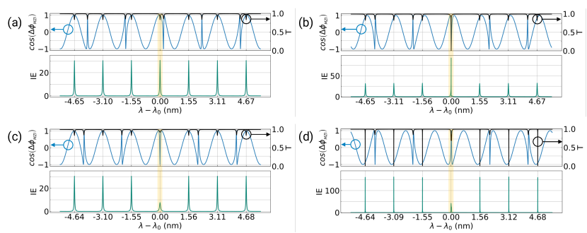
In Fig.2 we show the spectral transmission , the cosine of , and the intensity enhancement (IE) in the Main ring for different MZI and Aux configurations. The spectral position of the Aux resonances can be clearly seen as sharp variations in the otherwise smooth sinusoidal oscillations of . In Fig.2(a), , so is maximized and the Main ring is maximally over-coupled. The Aux is detuned from all the Main resonances, which are then unperturbed and have the same value of the IE. In Fig.2(b) we show the response of the structure with an Aux resonance matching a target Main resonance at the wavelength , which is highlighted in yellow. The Main ring becomes completely uncoupled at due to the additional phase imparted by the Aux resonator, which causes and sets the MZI to a completely destructive interference at its cross port.
Figure 2(c) shows the effect of a slight detuning of the MZI from the configuration shown in Fig.2(b). Here for all the resonances, and the phase shift given by the Aux does not uncouple the target resonance anymore because it causes . We choose the MZI detuning such that the target resonance is brought to a critical coupling condition when it is overlapped by the Aux (, where is the coupling coefficient for which the intrinsic loss perfectly balances the coupling loss with the input waveguide), while the other ones are still over-coupled. This condition is also clearly witnessed from the large IE at the target resonance.
In the last configuration, reported in Fig.2(d), we show that reverse behavior is possible as well: a target resonance in a comb of critically coupled ones can be brought to overcoupling due to the use of the Aux resonator. The IE at the target resonance is now greatly reduced compared to the neighboring ones. In Sec.III we will show that the Aux resonator can be swept continuously across the Main resonance, thus realizing all the coupling conditions described above.
III Experimental results
The device described in Sec.II is fabricated on a silicon nitride photonic chip. An optical microscope image is shown in Fig.3(a). Three metallic heaters allow us to respectively change the resonance wavelength of the Main ring, of the Aux resonator, and the phase of the bus-waveguide arm through the thermo-optic effect. The sample is mounted on a holder that is thermally stabilized, and the metallic micro-heaters are controlled by a voltage driver module. The waveguide has width of 1.75 m and thickness of 800 nm, while the gap between the Main resonator and the bus-waveguide is 0.4 m.
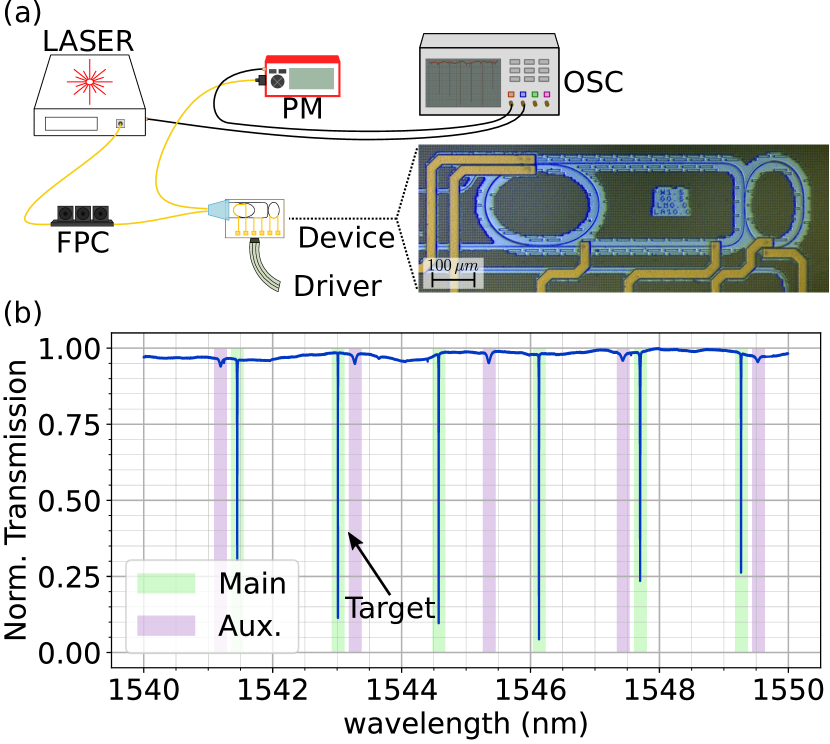
The setup used to probe the device transmission is shown in Fig. 3(a). A tunable laser is coupled to a fiber polarization controller (FPC) and the polarization is controlled to match that of the TE mode of the silicon nitride waveguide. Light is coupled into and out of the chip through a fiber array of UHNA4 fibers with a coupling loss of approximately 1.7 dB/facet. Then, the output signal is detected by a powermeter and recorded in real-time by an oscilloscope.
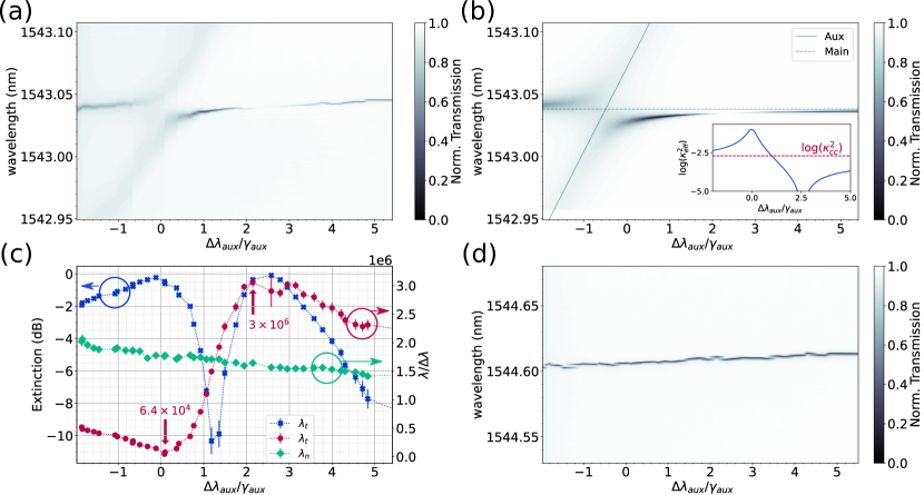
Initially, is set to ensure that all the resonances of the Main resonator which are not perturbed by the Aux are critically coupled. This configuration mimics that shown in Fig.2(d). Figure 3(b) shows the device transmission when the Aux resonances are all detuned from those of the Main resonator. We can distinguish the Main from the Aux resonances from their different free spectral range (FSR), linewidth and extinction. In particular, the resonances of low extinction are those of the Aux resonator because it is heavily overcoupled. The Main resonator has an FSR of nm. From the resonance linewidth in the critical coupling configuration we estimated an intrisic Q-factor of and . The FSR of the auxiliary resonator is 2.1 nm and , yielding a Q of . To demonstrate the change of the linewidth of a single resonance at (indicated with an arrow in Fig.3(b)) in the Main resonator, we recorded the transmission spectra at different detunings between the target resonance and the closest auxiliary resonance at . We then define the normalized distance between the two resonances as , where nm is the linewidth of the Aux resonance. The wavelength of the Aux resonance is swept from to in small steps. The different spectra are shown stacked in Fig.4(a), while Fig.4(b) reports calculated using Eq.(1), which shows a good agreement with the experimental results. From the stacked spectra in Fig.4(a) we extracted the extinction and the linewidth of the target resonance. In Fig.4(c) it is shown the quantity , which coincides with the Q-factor when the Aux is highly detuned from the target Main resonance, as the latter restores its natural Lorentzian shape. The simultaneous analysis of the extinction and of the linewidth allows us to assess how the effective coupling between the Main resonator and the bus-waveguide changes due to the phase imparted by the Aux resonator. When , the extinction is almost zero, and approaches the value of the intrinsic . In this configuration, the resonator is totally under-coupled at . This is also confirmed from the simulation of as a function of (inset in Fig.4(b)), where reaches its minimum value at . At , the extinction is maximized ( dB) and is half the intrinsic Q. This implies that the resonance is critically coupled, meaning that at , as shown in the inset of Fig.4(b). When , we have that reaches the minimum value of , with an extinction of dB, indicating an highly over-coupled resonance which is consistent with the maximum in shown in the inset of Fig.4(b).
To summarize, by sweeping the Aux resonance across the target resonance of the Main, we can continuously control between and , realizing all the coupling regimes described in Sec.II. To confirm that the control of the Q-factor is wavelength-selective, in Fig.4(c) we also report the linewidth of a resonance at nm, which is largely detuned from all Aux resonances. As changes, the Q-factor reMains mostly unperturbed. The stacked spectra around the resonance at are shown in Fig.4(d). The slight red-shift of the resonance wavelength is caused by the thermal cross-talk between the micro-heater on top of the Aux resonator and the Main resonator.
IV Conclusions
We proposed and experimentally validated an integrated photonic device consisting of a microresonator where the Q-factor of a single resonance can be selectively changed, leaving that of the other resonances unperturbed. This is accomplished by a resonant interferometric coupler, in which an auxiliary resonator allows us to change the interference condition in a very narrow-band spectral range. We theoretically investigated several configurations, in which one resonance of the Main resonator is tuned from being maximally over-coupled to be totally under-coupled, leaving the other resonances unchanged. We experimentally validated the working principle of the device on the silicon nitride platform. The fabricated device enables the selective switching of the quality factor of a target resonance from to . By adding more than one Aux resonator in the long arm of the MZI we could target different resonances and independently control them. Thus, our design is highly modular and scalable. Many applications that require the resonant control of the light matter interaction in nonlinear and quantum optics could benefit from our structure. Examples includes Q-switched lasers, wavelength-selective integrated parametric oscillators, entangled photon pair generation and photon pair sources with simultaneously high brightness heralding efficiency.
Acknowledgements
P.L.P. acknowledges funding from the HyperSpace project (project ID 101070168). D.B acknowledges the support of Italian MUR and the European Union - Next Generation EU through the PRIN project number F53D23000550006 - SIGNED. M.B., M.G and M.L. acknowledge the PNRR MUR project PE0000023-NQSTI. All the authors acknowledge the support of Xanadu Quantum Technology for providing the samples and the useful discussions.
References
- Qiang et al. [2007] Z. Qiang, W. Zhou, and R. A. Soref, Optical add-drop filters based on photonic crystal ring resonators, Optics express 15, 1823 (2007).
- Huang and Zhang [2020] Y. Huang and T. Zhang, An optical filter based on micro-ring resonator and bragg grating, in AOPC 2020: Optoelectronics and Nanophotonics; and Quantum Information Technology, Vol. 11564 (SPIE, 2020) pp. 24–27.
- Mokhtari [2021] M. Mokhtari, Tunable optical filter design with ring resonator based sagnac loop, Optik 242, 167068 (2021).
- Selim and Anwar [2023] M. A. Selim and M. Anwar, Enhanced q-factor and effective length silicon photonics filter utilizing nested ring resonators, Journal of Optics 25, 115801 (2023).
- Lin et al. [2022] D. Lin, S. Shi, W. Cheng, P. Liu, M. Lu, T. Lin, G. Hu, B. Yun, and Y. Cui, A high performance silicon nitride optical delay line with good expansibility, Journal of Lightwave Technology 41, 209 (2022).
- Shan et al. [2021] W. Shan, L. Lu, X. Wang, G. Zhou, Y. Liu, J. Chen, and L. Zhou, Broadband continuously tunable microwave photonic delay line based on cascaded silicon microrings, Optics Express 29, 3375 (2021).
- Steglich et al. [2021] P. Steglich, D. G. Rabus, C. Sada, M. Paul, M. G. Weller, C. Mai, and A. Mai, Silicon photonic micro-ring resonators for chemical and biological sensing: A tutorial, IEEE sensors journal 22, 10089 (2021).
- Kazanskiy et al. [2023] N. L. Kazanskiy, S. N. Khonina, and M. A. Butt, A review of photonic sensors based on ring resonator structures: Three widely used platforms and implications of sensing applications, Micromachines 14, 1080 (2023).
- Moradi et al. [2021] M. Moradi, M. Mohammadi, S. Olyaee, and M. Seifouri, Design and simulation of a fast all-optical modulator based on photonic crystal using ring resonators, Silicon , 1 (2021).
- Hagan et al. [2020] D. E. Hagan, M. Ye, P. Wang, J. C. Cartledge, and A. P. Knights, High-speed performance of a tdfa-band micro-ring resonator modulator and detector, Optics Express 28, 16845 (2020).
- Foster et al. [2011] M. A. Foster, J. S. Levy, O. Kuzucu, K. Saha, M. Lipson, and A. L. Gaeta, Silicon-based monolithic optical frequency comb source, Optics Express 19, 14233 (2011).
- Shen et al. [2020] B. Shen, L. Chang, J. Liu, H. Wang, Q.-F. Yang, C. Xiang, R. N. Wang, J. He, T. Liu, W. Xie, et al., Integrated turnkey soliton microcombs, Nature 582, 365 (2020).
- Kippenberg et al. [2018] T. J. Kippenberg, A. L. Gaeta, M. Lipson, and M. L. Gorodetsky, Dissipative kerr solitons in optical microresonators, Science 361, eaan8083 (2018).
- Kues et al. [2017] M. Kues, C. Reimer, P. Roztocki, L. R. Cortés, S. Sciara, B. Wetzel, Y. Zhang, A. Cino, S. T. Chu, B. E. Little, et al., On-chip generation of high-dimensional entangled quantum states and their coherent control, Nature 546, 622 (2017).
- Lei et al. [2019] X. Lei, C. Wieschendorf, J. Firth, F. Ladouceur, A. Fuerbach, and L. Silvestri, Numerical modelling and optimization of actively q-switched waveguide lasers based on liquid crystal transducers, Optics Express 27, 8777 (2019).
- Shtyrkova et al. [2019] K. Shtyrkova, P. T. Callahan, N. Li, E. S. Magden, A. Ruocco, D. Vermeulen, F. X. Kärtner, M. R. Watts, and E. P. Ippen, Integrated cmos-compatible q-switched mode-locked lasers at 1900nm with an on-chip artificial saturable absorber, Optics express 27, 3542 (2019).
- Miller et al. [2015] S. A. Miller, Y. Okawachi, S. Ramelow, K. Luke, A. Dutt, A. Farsi, A. L. Gaeta, and M. Lipson, Tunable frequency combs based on dual microring resonators, Optics express 23, 21527 (2015).
- Shoman et al. [2019] H. Shoman, H. Jayatilleka, A. H. Park, A. Mistry, N. A. Jaeger, S. Shekhar, and L. Chrostowski, Compact wavelength-and bandwidth-tunable microring modulator, Optics express 27, 26661 (2019).
- Liu et al. [2018] Y. Liu, A. R. Wichman, B. Isaac, J. Kalkavage, E. J. Adles, T. R. Clark, and J. Klamkin, Ultra-low-loss silicon nitride optical beamforming network for wideband wireless applications, IEEE Journal of Selected Topics in Quantum Electronics 24, 1 (2018).
- Zhang et al. [2021] Y. Zhang, Q. Liu, C. Mei, D. Zeng, Q. Huang, and X. Zhang, Proposal and demonstration of a controllable q factor in directly coupled microring resonators for optical buffering applications, Photonics Research 9, 2006 (2021).
- Rakshit et al. [2021] J. K. Rakshit, K. E. Zoiros, and G. K. Bharti, Proposal for ultrafast all-optical pseudo random binary sequence generator using microring resonator-based switches, Journal of computational Electronics 20, 353 (2021).
- Vernon et al. [2017] Z. Vernon, M. Menotti, C. Tison, J. Steidle, M. Fanto, P. Thomas, S. Preble, A. Smith, P. Alsing, M. Liscidini, et al., Truly unentangled photon pairs without spectral filtering, Optics letters 42, 3638 (2017).
- Chen et al. [2023] N. Chen, Z. Wang, J. Wu, H. Li, S. He, Z. Fan, Y. Fan, X. Zhang, Q. Zhou, and J. Xu, Pushing photon-pair generation rate in microresonators by q factor manipulation, Optics Letters 48, 5355 (2023).
- Burridge et al. [2023] B. M. Burridge, I. I. Faruque, J. G. Rarity, and J. Barreto, Integrate and scale: A source of spectrally separable photon pairs, arXiv preprint arXiv:2303.17258 (2023).
- Wen et al. [2012] Y. H. Wen, O. Kuzucu, M. Fridman, A. L. Gaeta, L.-W. Luo, and M. Lipson, All-optical control of an individual resonance in a silicon microresonator, Physical Review Letters 108, 223907 (2012).
- Wen et al. [2011] Y. H. Wen, O. Kuzucu, T. Hou, M. Lipson, and A. L. Gaeta, All-optical switching of a single resonance in silicon ring resonators, Optics letters 36, 1413 (2011).
- Guo et al. [2021] T. Guo, S. Gao, H. Zeng, L. Tang, and C. Qiu, All-optical control of a single resonance in a graphene-on-silicon nanobeam cavity using thermo-optic effect, Journal of Lightwave Technology 39, 4710 (2021).
- Chen et al. [2007] L. Chen, N. Sherwood-Droz, and M. Lipson, Compact bandwidth-tunable microring resonators, Optics letters 32, 3361 (2007).
- Manipatruni et al. [2008] S. Manipatruni, C. B. Poitras, Q. Xu, and M. Lipson, High-speed electro-optic control of the optical quality factor of a silicon microcavity, Optics letters 33, 1644 (2008).
- Xue et al. [2015] X. Xue, Y. Xuan, P.-H. Wang, Y. Liu, D. E. Leaird, M. Qi, and A. M. Weiner, Normal-dispersion microcombs enabled by controllable mode interactions, Laser & Photonics Reviews 9, L23 (2015).
- Gentry et al. [2016] C. M. Gentry, G. T. Garcés, X. Zeng, and M. A. Popović, Tailoring of individual photon lifetimes as a degree of freedom in resonant quantum photonic sources, in CLEO 2016: Conference on Lasers and Electro-Optics, JTu5A.17 (Optica Publishing Group, 2016).