Orbital Angular Momentum Beam assisted High-Order Harmonic Generation in Semiconductor Materials
Abstract
We investigate the use of light beams carrying orbital angular momentum (OAM) in the context of high harmonic generation (HHG) within semiconductor crystals. Our contribution deals with the transfer and conservation of OAM in the strong-field regime, from the driving laser field to the generated harmonics. To this end, in this work, we combine the semiconductor Bloch equations with the thin slab model to simulate the generation of high-order harmonics in semiconductor media and to compute the features of the far-field harmonics. We demonstrate that this theoretical approach is capable of satisfactorily reproduce previously published experimental features of the generated harmonics in ZnO driven by a Laguerre-Gauss beam. Our research not only deepens the understanding of light-solid interactions but also heralds the dawn of bright, structured XUV coherent radiation sources with unparalleled potential across diverse technological areas, paving the way for enhanced functionalities in fields such as microscopy, spectroscopy, and optical communication.
keywords:
nonlinear optics, ultrafast photonics, extreme-ultraviolet radiation, light−matter interaction, structured beamsTechnion - Israel Institute of Technology, Haifa, 32000, Israel \alsoaffiliationGuangdong Provincial Key Laboratory of Materials and Technologies for Energy Conversion, Guangdong Technion - Israel Institute of Technology, 241 Daxue Road, Shantou, Guangdong, China, 515063 \alsoaffiliationTechnion - Israel Institute of Technology, Haifa, 32000, Israel \alsoaffiliationGuangdong Provincial Key Laboratory of Materials and Technologies for Energy Conversion, Guangdong Technion - Israel Institute of Technology, 241 Daxue Road, Shantou, Guangdong, China, 515063 \alsoaffiliationTechnion - Israel Institute of Technology, Haifa, 32000, Israel \alsoaffiliationGuangdong Provincial Key Laboratory of Materials and Technologies for Energy Conversion, Guangdong Technion - Israel Institute of Technology, 241 Daxue Road, Shantou, Guangdong, China, 515063 \abbreviationsIR,NMR,UV
1 Introduction
High harmonic generation (HHG) has emerged as a pivotal phenomenon in the field of nonlinear optics, with significant implications spanning both basic scientific research and industrial applications. Initially explored in dilute atomic gases, HHG has recently garnered considerable attention in solid-state media, particularly in bulk semiconductor crystals 1, 2, 3, 4, 5. The distinctive characteristics of solid-state HHG, including its efficiency and potential for integration into high-repetition-rate nanoscale devices, have sparked intense investigation into its underlying mechanisms and practical implementations 6, 2, 3.
Since its first observation in bulk semiconductor crystals in 2011 7, solid-state HHG has been a subject of extensive research endeavors aimed at unraveling its fundamental principles, more recently devoted to the role of symmetries in the harmonic selection rules 8. Unlike HHG in gases, the harmonics in solids are generated within a high-density, periodic crystal structure (in the last layers with a thickness of tens of nanometers). Additionally, solid-state HHG exhibits a lower intensity threshold compared to gas-phase HHG, making it particularly suitable for high-repetition-rate applications.
Due to the complexity of the interaction between the solid structure and the strong laser field, distinct theoretical models have been developed to comprehend the process effectively. The more renowned theories are the Time-dependent Schrödinger equation (TDSE) 9, the semiconductor Bloch equations (SBE) 10, and the time-dependent density functional theory (TDDFT) 11. Both the TDSE and SBE models are mainly based on the strong-field approximation and solve the laser-matter interaction problem under the single active electron (SAE) approximation. The TDDFT method offers a unique possibility of solving the many-body problem considering both electron-electron correlations and the full electronic band structure 12. Contrary to HHG in gases, there is no unified theoretical description for the generation of harmonics in solids. This makes it imperative to delve into new scenarios where our understanding of this intriguing phenomenon can be tested.
The previously mentioned models enable us to address the microscopic aspects of solid-state HHG, specifically how individual emitters (electrons) respond to the strong laser field. However, there is an additional dimension to consider: the propagation of these generated high-order harmonics. It is well known that both gas-phase and solid-state HHG are collective phenomena. To obtain a measurable number of photons, the coherent sum and phase-matched emission of many emitters, typically ranging from to , are required 13. Therefore, modeling both aspects presents a formidable computational challenge 14. To reduce the problem complexity, one could assume, for instance, that the phase-matching conditions are achieved and study the behavior of the near and far harmonic fields. Additionally, in solid-state HHG, it is reasonable to assume that the high-order harmonic radiation, typically in the XUV range, where most semiconductors are opaque, is produced in the last layers of the material (in a transmission-based setup), simplifying the modeling of its propagation even further.
In addition, one intriguing aspect of solid-state HHG lies in its capacity for tailored generation media, offering a unique degree of freedom absent in gas-phase HHG 6, 15. Through precision patterning of the crystal surface, researchers can exert macroscopic control over the generation and emission of high-order harmonics 6. This capability opens new avenues for designing novel refractive or diffractive optics within the solid-state medium, enabling the creation of customized harmonic beams with specific properties.
A recent breakthrough in the field has been the verification of the transfer and conservation of orbital angular momentum (OAM) from the driving laser to the high-order harmonics in both solid-state 6, 16 and gas-phase 17. The generation of high-order harmonics carrying OAM was experimentally demonstrated, but the results were controversial as the law of OAM upscaling was not followed 18. These results strictly contradicted the findings from the Lewenstein model and the perturbative second harmonic generation. In 19, the authors theoretically investigated the non-perturbative process of HHG pumped by OAM beams and revealed that there is indeed an OAM buildup in different harmonic orders in accordance with the law of OAM upscaling. These findings were experimentally verified soon after 17. Now, it is well-established that when an intense OAM beam interacts with an atomic gas target, the OAM imprinted by the beam in the target media is conserved and that the generated harmonics obey the upscaling law of the OAM: ( being the harmonic order, and denotes the OAM of the driving laser beam) 20. Interestingly, the generation of extreme-ultraviolet self-torque beams, i.e., the creation of light beams with time-varying OAM, has also been demonstrated in gas-phase HHG driven by time-delayed pulses with different OAMs 21. Additionally, exploring the vectorial nature of the OAM beams provides an additional degree of freedom to control this extreme nonlinear process. HHG driven by vector vortex beams (VVBs) has shown a remarkable feature: the conversion efficiency of the generated vector vortex harmonics increases with an increase in the OAM of the driving VVB 22. However, to our knowledge, there is not a theoretical model that describes the interaction of an intense OAM beam with a solid medium such as a semiconductor crystal.
In this contribution, we explore solid-state HHG driven by an OAM beam. We theoretically investigate the non-perturbative process of HHG driven by a Laguerre–Gaussian (LG) laser beam carrying an OAM, , in a ZnO crystal, demonstrating the conservation of OAM (i.e., the multiplicative rule for OAM), and nearly similar divergence of the emitted harmonics. To this end, we combine two well-established theories: The SBE model, which allows us to calculate the crystal response to the external field in the dipole approximation limit, and the thin-slab model, which allows us to calculate the near and far-field amplitudes of the resulting harmonic vortices.
2 Theory of OAM laser field driven high-order harmonic generation in semiconductor materials
Solid-HHG, particularly the interband contribution to the process, can be schematically understood in a way similar to the three-step model in atoms 23. Initially, an electron residing in a valence band is pre-accelerated by the strong laser field towards the -point of the Brillouin zone. Here, the transition probability to the conduction band reaches its maximum. Thus, the electron undergoes a dipole transition from the valence band to the conduction band, resulting in the creation of an electron-hole pair that is subsequently accelerated by the laser field in their respective bands. During this stage, the electron and hole experience distinct Bloch oscillations due to differences in the band structure in which their dynamics is taking place. Finally, the electron-hole pair recombines in the vicinity of the -point, thereby generating high-order harmonics with a cut-off solely determined by the band gap during the time of recombination. This schematic description outlines the generation of harmonics with energies above the material’s band gap. There exist however, harmonics below the energy band gap of the material. In intraband harmonic generation, electrons oscillate within the same energy band at high frequencies, resulting in the emission of harmonic radiation. For calculating the harmonic spectra, we utilize a one-dimensional (1D)-SBE model. The fundamental premise of the SBE lies in their ability to comprehensively capture the evolution of the electron wavefunction across the reciprocal space domain. This comprehensive approach is crucial for understanding how electrons respond to the complex interplay between the crystal’s periodic potential and the external laser field, particularly in scenarios where the laser field strength is sufficiently intense to induce nonlinear optical effects. The SBE can be written in terms of the interband coherence (polarization) and the occupation of electrons (holes) as (in a.u.):
| (1) | |||||
where are the single particle energies of the electrons (holes), is the dephasing time of the polarization, is the (-dependent) dipole transition matrix element between the valence and conduction band, and , is the spatio-temporal laser driving field. From Eqs. (2) we can compute the total time-dependent interband polarization and intraband current density as 5:
| (2) | |||||
| (3) |
where is the group velocity of the electrons (holes) defined by . The total emitted spectral intensity can be calculated as:
| (4) |
Furthermore, for the sake of simplicity, we consider only integration in one dimension, which corresponds to the most effective direction in the crystals, and the contribution of the interband polarization .
The spatio-temporal complex field amplitude of a linearly polarized LG beam is given by:
| (5) |
with the temporal part defined as:
| (6) |
Here, , , , , and represent the peak electric field amplitude, the OAM, the radial index, the Gaussian beam waist, and the Gouy phase of the LG beam, respectively. Here, , and represent the phase front radius, and the width of the beam at some finite propagation distance , where is the Rayleigh length, and is the wavenumber. In Eq. (6), is the total number of cycles in the laser field pulse, and ( being the central frequency of the laser) is the laser period. In our numerical simulations, we have considered a zero radial index i.e., , which led to , to ensure that the input LG beam profile has only one radial ring. It is also important to highlight that the dipole approximation is valid in our calculation. This allows us to disregard the spatial part and concentrate solely on the temporal aspect of the spatio-temporal complex field amplitude of the LG beam in the numerical solution of the SBE. This choice is justified by the characteristic lengths in our model: The lattice spacing in the ZnO semiconductor ( nm) and the electron (and hole) excursion distance, which is approximately nm within their respective bands. These distances are significantly smaller compared to the wavelength of the driving laser beam, m. This approximation allow us to substitute . We solve numerically the SBEs equations, Eqs. (2) for a system of two bands (one conduction and one valence), for the ZnO band structure 2.
In semiconductor crystals, particularly in a transmission geometry setup, harmonic generation typically involves the laser beam propagating through the crystal and being focused onto the back surface. Consequently, harmonics predominantly originate in the last layers of the crystal. Harmonics generated deeper within the crystal are heavily absorbed, resulting in the primary contribution to overall harmonics occurring within the last tens of nanometers. This phenomenon allows for using a straightforward and efficient model, known as the thin-slab model (TSM) 20, as will be show in the next subsection.
2.1 Thin-slab model in semiconductors
The thin-slab model (TSM) provides insights into how the orbital angular momentum (OAM) carried by the incident laser field is transferred to the harmonics generated in the extreme ultraviolet (XUV) regime through the non-perturbative HHG process. Here, we will particularly investigate a Laguerre-Gaussian (LG) beam in the near-infrared (NIR) regime interacting with a ZnO crystal. By taking advantage of the fact that the HHG process occurs in the last layers of the crystal, we simplify the crystal representation to a thin 2D slab oriented perpendicular to the propagation direction of the incident LG beam. Combining the TSM with the 1D-SBE, we can analyze the near-field amplitude and phase profiles of various harmonic orders. Subsequently, employing the Fraunhofer diffraction integral facilitates the computation of far-field amplitude and phase profiles for these harmonic orders. In our model, we position the slab precisely at the focal point of the LG beam (i.e., at ), enabling us to mitigate phase mismatch effects arising from the curved wavefront of the LG beam (focal phase) and its focusing (Gouy phase). We start by calculating the complex spatial beam profile of the fundamental LG beam in the thin slab, positioned at the beam focus i.e., at . This profile can be written as:
| (7) |
The spatial amplitude and phase components of the fundamental LG beam, as given in Eq. (5), are accommodated in and , respectively. The next step in the model is to consider that the harmonics are emitted at the thin slab due to the nonlinear interaction of the LG beam with the atoms placed periodically. Therefore, the near-field amplitude of the harmonic is calculated as:
| (8) |
Here, is a scaling factor unique to each harmonic order and is obtained from the 1D SBE simulations. To extract the value of for different harmonics, it is necessary to calculate various harmonic spectra with different laser field intensities within a small range. After calculating the near-field amplitude with the help of Eq. (8), we use the Fraunhofer diffraction integral to compute the far-field amplitude and phase profile of the different harmonic orders. Unlike gas-phase HHG, we did not take into account the dipole phase contribution while computing the near-field complex amplitude for solids in this model. Therefore, essentially, it is the TSM with null dipole phase. The far-field complex amplitude of the harmonic order is thus given by:
| (9) |
Here, (,) are the far-field coordinates, representing the divergence and the azimuthal coordinate, respectively. denotes the wavelength of the order harmonic, and represents the Bessel function of the order . In Eq. (9), we can observe that the phase of the harmonic order scales as , where is the fundamental beam’s helical phase and equals . This implies that the OAM of the order harmonic is equal to times the OAM of the fundamental beam, i.e., . Hence, the upscaling law of OAM holds when HHG is driven by an LG beam in a semiconductor crystal.
Additionally, to explore the hidden spatial features of different harmonic orders, such as their intensity ring thickness and divergence profile, we calculate the far-field intensity as:
| (10) |
from which we can extract the far-field transverse intensity distribution for different harmonic orders:
| (11) | |||||
Using Eq. (11), we can calculate the intensity profile of different harmonic orders. In the following section, we will present the numerical simulation results obtained with our model, used to compute the near and far-field harmonic amplitudes, and subsequently compare them with the experimental results presented in Ref. 6.
3 Results and discussion
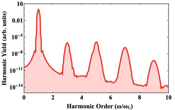
We calculate twelve different harmonic spectra by solving the 1D SBE model given in Eqs. (2) to extract the scaling factor . In our numerical simulation, we use a sin2-shaped laser pulse with 15 total cycles and a central wavelength of m. The total laser pulse duration is approximately 80 fs. The laser intensity varies from 2 to 2.5 W/cm2 (corresponding to peak electric fields between and 0.0024 a.u and 0.0027 a.u.). More importantly, we consider a phenomenological dephasing time of 2 fs. This makes the contribution of the short electron trajectories dominant 2. The parameters used in our simulation are consistent with the experimental parameters used in Ref. 6. The calculations were performed using the orientation symmetry of the reciprocal lattice defined by , and . For this symmetry, the lattice parameters are defined by a.u., as used in Ref. 2. For the 1D-SBE model, we use a linearly polarized laser electric field both in the and orientations, for which similar results were obtained. Here, we show the results for the crystal orientation in the direction. An example of the calculated spectrum is shown in Fig. 1.
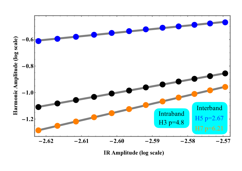
In the experimental work reported in Ref. 6, the analysis on the transfer of the OAM from the fundamental beam to the generated harmonics focused on the , , and harmonic orders. To compare these experimental results with our theoretical calculations, we analyze the variations in the same harmonic amplitudes as a function of the fundamental field amplitude (both in log scale) as shown in Fig. 2. By fitting the resulting amplitude scaling, we extract the value of for the different harmonic orders. The resulting values of were found to be , , and for the , , and harmonics, respectively (see Fig. 2). Notice that for the driving laser field, the photon energy is eV. Thus, eV, which is below the band gap energy of ZnO ( eV). This situates the harmonic in a region where neither a perturbative nor a non-perturbative scaling law is followed 2.
After obtaining the values for different harmonic orders, we plot their corresponding transverse intensity profiles using Eq. (11). This, in turn, provides us with some significant insights into the far-field spatial profile of the harmonic vortices. The transverse intensity profiles for the (a) fundamental LG beam, (b) harmonic, (c) harmonic, and (d) harmonic are shown in Figs. 3(a)-(d), respectively. In the insets of these intensity plots, we also show the far-field phase profile for different harmonic orders, computed using Eq. (9). The value of the OAM for different harmonic orders can be obtained by counting the number of phase shifts along the azimuthal direction, which are 3, 5, and 7 for the harmonic orders , , and , respectively. From the transverse intensity plots, two important characteristics can be observed: (i) the enhancement of the size of the central dark core with the harmonic order, and (ii) the thickness of the ring decreases with the harmonic order.
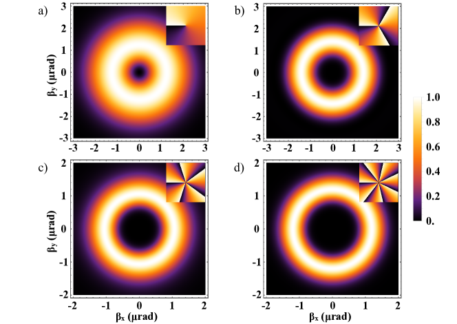
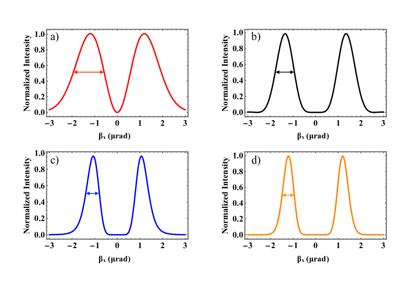
To quantify the vortex ring size for different harmonics, we depict the line intensity profile given by Eq. (11) for . The profiles are shown in Fig. 4. We define the thickness of the ring for different harmonic vortices as the full width at half maximum (FWHM) of the intensity profiles. This is illustrated with the colored horizontal arrows in Fig. 3(a)-(d). The different thickness values were found to be (a) 1.27 rad, (b) 0.84 rad, (c) 0.59 rad, and (d) 0.54 rad. This demonstrates the decreasing nature of the ring thickness with the harmonic order.
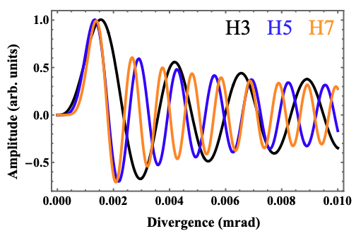
We further investigate whether the harmonics are emitted with similar divergence. It has been demonstrated both theoretically and experimentally that different harmonics are emitted with similar divergence when HHG is driven by an OAM beam in atomic gases. However, this feature has never been studied in the case of solid-HHG. For this analysis, we compute the radius at which the function is maximum (the divergence is quantified as the radius of maximum intensity in the case of light beams carrying OAM). This maximum radius was found to be . Then, we depict the amplitude of the integrand of Eq. (9), as a function of the divergence for the , , and harmonic orders. The divergence, where the integrand is maximized, is very similar for all the harmonic orders, as shown in Fig. 5. This behavior of the solid-phase harmonics also resembles that of the gas-phase harmonics. The similar divergence for different harmonics, when HHG is driven by an OAM beam either in solid or in gas phase, can be thought of as a consequence of the OAM build-up law. In fact, this can be disentangled from the far-field complex harmonic amplitude, given by Eq. (9). In the TSM, the dependence on the divergence is encoded in the argument of the Bessel function, which is a part of the amplitude of the integrand. The order of this Bessel function is also related to the OAM of the harmonic () generated via HHG. The argument of the Bessel function, which is directly proportional to the divergence, is also inversely proportional to the wavelength of the order harmonic, i.e., . Therefore, both the argument and the order of the Bessel function are proportional to the harmonic order. This is the reason why the position of the maximum amplitude of the integrand of Eq. (9) remains nearly the same for the harmonic orders considered in our case.
It is a well-known fact that the harmonic amplitude scales differently with the fundamental field amplitude in the perturbative and non-perturbative case. In the non-perturbative case, this scaling factor lies significantly below the harmonic order. In our numerical simulation, the scaling law clearly follows this principle for the 5 and 7 harmonics, but not for the 3 one, whose photon energy ( eV) lies below the band gap energy of ZnO ( eV). Therefore, for this harmonic, it is necessary to use the intraband current to calculate its corresponding -value. The fact that the energy of the 3 harmonic stands below the ZnO band gap could explain the different scaling behavior (see Fig. 2). On the other hand, even when the harmonic energy is above the band gap energy, our results suggest that a very different scaling law is observed for other individual harmonics (5 and 7 in our case), contrary to the atomic case where the scaling law is approximately the same for the harmonics located in the plateau region of the HHG spectrum 24. This is not surprising, since the dynamics of the electron are constrained by the band dispersion relation in solids, which is not the case for atomic gases, where it can be considered free, if the laser electric field is strong enough. Furthermore, these results are not affected by changes in the dephasing time ( in our model). It is also noteworthy that for harmonics in the plateau region, many quantum paths interfere to generate these individual harmonics, giving rise to complicated scaling laws that deviate from the behavior observed here.
With our theoretical model, we observed two main characteristics of the HHG generated by the interaction of an intense LG laser field with the ZnO semiconductor: (i) The ring thickness in the transverse intensity distribution decreases as the harmonic order increases (as shown in Fig. 3 for the transverse intensity distribution and in Fig. 4), and (ii) the multiplicative rule for the OAM of the harmonics, i.e., the OAM of the order harmonic is given by (see the insets of Fig. 3). This multiplicative rule for different harmonic orders results in the emission of harmonics with nearly similar divergence. These results are in agreement with the experimental findings of Ref. 6, where these features were demonstrated experimentally. The emission of different harmonics with nearly identical divergence may provide a unique route to generate attosecond helical pulses.
4 Conclusions and Outlook
Our theoretical investigation into high-order harmonic generation (HHG) in ZnO semiconductor, assisted by an intense Laguerre-Gaussian (LG) beam carrying orbital angular momentum (OAM) with , reveals several key findings: (i) The scaling laws for different harmonic orders positioned within the plateau of the HHG spectrum exhibit significant deviations from the atomic case; (ii) The size of the harmonic vortices decreases as the harmonic order increases and (iii) The law of OAM up-scaling, indicating the conservation of OAM via HHG, persists, leading to the generation of harmonics with nearly identical divergence.
Our theoretical results align very well with the experimental findings presented in 6. The integration of a 1D SBE model with the TSM proves to be effective in describing this nonlinear interaction. The application of this model in solid-state HHG provides opportunities to explore selection rules considering various degrees of freedom, such as OAM, spin angular momentum (SAM), symmetry of the generating media, and the laser field. Furthermore, our future investigations may involve applying this theoretical approach to analyze the interaction of solid-state media with different spatially structured beams, such as Bessel-Gauss (BG) and perfect optical vortex (POV) beams, offering avenues for deeper exploration into solid-state HHG nonlinear dynamics.
We acknowledge financial support from the Guangdong Province Science and Technology Major Project (Future functional materials under extreme conditions - 2021B0301030005) and the Guangdong Natural Science Foundation (General Program project No. 2023A1515010871).
References
- Vampa et al. 2014 Vampa, G.; McDonald, C. R.; Orlando, G.; Klug, D. D.; Corkum, P. B.; Brabec, T. Theoretical Analysis of High-Harmonic Generation in Solids. Phys. Rev. Lett. 2014, 113, 073901
- Vampa et al. 2015 Vampa, G.; McDonald, C.; Fraser, A.; Brabec, T. High-Harmonic Generation in Solids: Bridging the Gap Between Attosecond Science and Condensed Matter Physics. IEEE J. Sel. Top. Quantum Electron. 2015, 21, 1–10
- Vampa and Brabec 2017 Vampa, G.; Brabec, T. Merge of high harmonic generation from gases and solids and its implications for attosecond science. J. of Phys. B 2017, 50, 083001
- Yue and Gaarde 2022 Yue, L.; Gaarde, M. B. Introduction to theory of high-harmonic generation in solids: tutorial. J. Opt. Soc. Am. B 2022, 39, 535–555
- Luu and Wörner 2016 Luu, T. T.; Wörner, H. J. High-order harmonic generation in solids: A unifying approach. Phys. Rev. B 2016, 94, 115164
- Gauthier et al. 2019 Gauthier, D.; Kaassamani, S.; Franz, D.; Nicolas, R.; Gomes, J.-T.; Lavoute, L.; Gaponov, D.; Février, S.; Jargot, G.; Hanna, M.; Boutu, W.; Merdji, H. Orbital angular momentum from semiconductor high-order harmonics. Opt. Lett. 2019, 44, 546–549
- Ghimire et al. 2011 Ghimire, S.; DiChiara, A.; Sistrunk, E.; Agostini, P.; DiMauro, L. F.; Reis, D. Observation of high-order harmonic generation in a bulk crystal. Nat. Phys. 2011, 7, 138–141
- Uzan-Narovlansky et al. 2023 Uzan-Narovlansky, A. J.; Orenstein, G.; Shames, S.; Even Tzur, M.; Kneller, O.; Bruner, B. D.; Arusi-Parpar, T.; Cohen, O.; Dudovich, N. Revealing the Interplay between Strong Field Selection Rules and Crystal Symmetries. Phys. Rev. Lett. 2023, 131, 223802
- Óscar Zurrón et al. 2018 Óscar Zurrón,; Picón, A.; Plaja, L. Theory of high-order harmonic generation for gapless graphene. New J. Phys. 2018, 20, 053033
- Haug and Koch 2009 Haug, H.; Koch, S. W. Quantum theory of the optical and electronic properties of semiconductors; World Scientific Publishing Company, 2009
- Runge and Gross 1984 Runge, E.; Gross, E. K. U. Density-Functional Theory for Time-Dependent Systems. Phys. Rev. Lett. 1984, 52, 997–1000
- van Leeuwen 1999 van Leeuwen, R. Mapping from Densities to Potentials in Time-Dependent Density-Functional Theory. Phys. Rev. Lett. 1999, 82, 3863–3866
- Hernández-García et al. 2010 Hernández-García, C.; Pérez-Hernández, J. A.; Ramos, J.; Jarque, E. C.; Roso, L.; Plaja, L. High-order harmonic propagation in gases within the discrete dipole approximation. Phys. Rev. A 2010, 82, 033432
- Gaarde et al. 2008 Gaarde, M. B.; Tate, J. L.; Schafer, K. J. Macroscopic aspects of attosecond pulse generation. J. Phys. B 2008, 41, 132001
- You et al. 2018 You, Y.; Reis, D.; Ghimire, S. Anisotropic high-harmonic generation in bulk crystals. Nat. Phys. 2018, 13, 345*349
- Kong et al. 2019 Kong, F.; Zhang, C.; Larocque, H.; Bouchard, F.; Li, Z.; Taucer, M.; Brown, G.; Severino, S.; Hammond, T. J.; Karimi, E.; Corkum, P. B. Spin-constrained orbital-angular-momentum control in high-harmonic generation. Phys. Rev. Res. 2019, 1, 032008
- Gariepy et al. 2014 Gariepy, G.; Leach, J.; Kim, K. T.; Hammond, T. J.; Frumker, E.; Boyd, R. W.; Corkum, P. B. Creating High-Harmonic Beams with Controlled Orbital Angular Momentum. Phys. Rev. Lett. 2014, 113, 153901
- Zürch et al. 2012 Zürch, M.; Kern, C.; Hansinger, P.; Dreischuh, A.; Spielmann, C. Strong-field physics with singular light beams. Nat. Phys. 2012, 8, 743–746
- Hernández-García et al. 2013 Hernández-García, C.; Picón, A.; San Román, J.; Plaja, L. Attosecond Extreme Ultraviolet Vortices from High-Order Harmonic Generation. Phys. Rev. Lett. 2013, 111, 083602
- Paufler et al. 2019 Paufler, W.; Böning, B.; Fritzsche, S. High harmonic generation with Laguerre–Gaussian beams. J. Opt. 2019, 21, 094001
- Rego et al. 2019 Rego, L.; Dorney, K. M.; Brooks, N. J.; Nguyen, Q. L.; Liao, C.-T.; Román, J. S.; Couch, D. E.; Liu, A.; Pisanty, E.; Lewenstein, M.; Plaja, L.; Kapteyn, H. C.; Murnane, M. M.; Hernández-García, C. Generation of extreme-ultraviolet beams with time-varying orbital angular momentum. Science 2019, 364, eaaw9486
- de las Heras et al. 2022 de las Heras, A.; Pandey, A. K.; Román, J. S.; Serrano, J.; Baynard, E.; Dovillaire, G.; Pittman, M.; Durfee, C. G.; Plaja, L.; Kazamias, S.; Guilbaud, O.; Hernández-García, C. Extreme-ultraviolet vector-vortex beams from high harmonic generation. Optica 2022, 9, 71–79
- Amini et al. 2019 Amini, K.; Biegert, J.; Calegari, F.; Chacón, A.; Ciappina, M. F.; Dauphin, A.; Efimov, D. K.; de Morisson Faria, C. F.; Giergiel, K.; Gniewek, P., et al. Symphony on strong field approximation. Rep. Prog. Phys. 2019, 82, 116001
- Rego et al. 2017 Rego, L.; Román, J. S.; Plaja, L.; Picón, A.; Hernández-García, C. Ultrashort extreame ultraviolet vortices; INTECH, 2017