RIS-Assisted OTFS Communications: Phase Configuration via Received Energy Maximization ††thanks: This publication has emanated from research conducted with the financial support of Science Foundation Ireland under Grant numbers SFI/21/US/3757 and SFI/19/FFP/7005(T).
Abstract
In this paper, we explore the integration of two revolutionary technologies, reconfigurable intelligent surfaces (RISs) and orthogonal time frequency space (OTFS) modulation, to enhance high-speed wireless communications. We introduce a novel phase shift design algorithm for RIS-assisted OTFS, optimizing energy reception and channel gain in dynamic environments. The study evaluates the proposed approach in a downlink scenario, demonstrating significant performance improvements compared to benchmark schemes in the literature, particularly in terms of bit error rate (BER). Our results showcase the potential of RIS to enhance the system’s performance. Specifically, our proposed phase shift design technique outperforms the benchmark solutions by over 4 dB. Furthermore, even greater gains can be obtained as the number of RIS elements increases.
Index Terms:
RIS, OTFS modulation, delay-Doppler, 6G.I Introduction
Reconfigurable intelligent surfaces (RISs) have gained attention due to increased connectivity demands and the surge in mobile data traffic. This state-of-the-art technology is set to play a crucial role in 6th-generation wireless networks (6G). RIS is a surface composed of electromagnetic metamaterial with numerous small, cost-effective, and energy-efficient reflecting elements [1]. These elements can manipulate the scattering and propagation in the wireless channel by applying a predetermined phase shift to the incoming wave. Effectively, RIS technology presents a transformative paradigm shift, that can convert the unpredictable and disruptive propagation environment into a smart radio setting. This results in an improvement of received signal quality and provides a revolutionary advancement in wireless communications [2].
On the other hand, orthogonal time frequency space (OTFS) modulation has emerged as a novel solution to address the diverse requirements of the 5th-generation wireless networks (5G), particularly in scenarios with high mobility, such as vehicle-to-vehicle communication and high-speed trains [3]. Traditional modulation schemes like orthogonal frequency division multiplexing (OFDM) face challenges in maintaining effective channel estimation at high speeds. In contrast, OTFS introduces a revolutionary approach by transforming the time-varying multipath channel into a two-dimensional domain, specifically the delay-Doppler (DD) domain [3, 4]. Such transformation, combined with equalization in the DD domain, ensures that each transmitted symbol experiences a nearly constant channel gain. This process involves spreading all information symbols across both time and frequency dimensions, which leads to the exploitation of maximum effective diversity [5]. Hence, OTFS proves to be a flexible modulation technique that combines features from both code division multiple access (CDMA) and OFDM [3].
The inherent benefits of both RIS and OTFS have inspired researchers to integrate these cutting-edge technologies to create a robust and energy-efficient approach, effectively tackling challenges at high-speed wireless communications. Specifically, in [6] and [7], RIS-aided OTFS modulation was proposed to improve the performance of OTFS, and the relative DD domain input-output relationship was derived. The authors in [8, 9] investigated a hybrid RIS-aided millimeter wave OTFS system and proposed a message-passing algorithm to perform channel estimation and data detection simultaneously. In addition, in [10] a novel channel estimation technique was proposed to reduce the training overhead in an RIS-aided OTFS setup. Inspired by the approach utilized in RIS-assisted OFDM systems, the researchers in [11] and [12] proposed a phase shift adjustment method only focusing on the strongest cascaded path. Despite the algorithm’s advantage of low complexity, its focus on the energy of a single path limits its ability to deliver superior performance, particularly in situations featuring multiple taps (paths) with close gains. Furthermore, this technique does not account for the time-varying nature of the channel.
Most studies investigating RIS have primarily concentrated on single-carrier scenarios for phase adjustment. Even in OFDM systems, where the entire bandwidth is considered, there has been a neglect of accounting for time variations of the channel in high-speed scenarios. Against this background, we investigate the RIS-assisted OTFS system in this paper and establish a connection with conventional OTFS without RIS. This paper considers the complete bandwidth of an OTFS block and assumes fixed phase shifts of RIS elements throughout an OTFS time frame. Hence, we introduce a phase shift design algorithm wherein the RIS is configured to address all paths and considers the dynamic nature of the channel. The key contributions of this paper are as follows:
-
•
We study the RIS-assisted OTFS system in a downlink scenario where the base station (BS) transmits the OTFS signal to a high-speed mobile terminal (MT) via reflection through an RIS. We find the characteristics of the cascaded channel that can be treated as a multipath channel with an increased number of taps. This finding indicates that both the delay time of the BS-RIS link and the Doppler shift of the RIS-MT link contribute to the gain of the cascaded path.
-
•
We propose a phase shift design to maximize the received energy at the receiver while enhancing the channel gain. In the proposed design, we consider the delay-Doppler (DD) channel to effectively collect the energy of all channel taps within the entire OTFS time frame to tackle time variations of the channel. Hence, in this paper, the variations in the channel across both time and frequency domains contribute to the phase shift adjustment. The proposed algorithm has low complexity by taking advantage of the sparsity of the DD channel.
-
•
Finally, we investigate the performance of the system through numerical analyses and compare the bit error rate (BER) performance results with those of the benchmark schemes. The results show that the RIS can significantly enhance the system’s performance. This enhancement follows the results obtained for RIS-assisted single carrier systems. In addition, we show that the proposed phase shift design substantially outperforms the benchmark schemes [11, 12]. The performance gain over the benchmark schemes is more than 4 dB. This superiority increases with an increasing number of RIS elements.
Notation: Boldface lower-case letters denote column vectors, and boldface upper-case letters denote matrices. and represent the real and imaginary components of a scalar/vector, respectively. signifies the optimum value of a scalar/vector variable, while denotes the complex conjugate. The transpose and Hermitian are denoted by and , respectively. indicates the complex normal distribution with mean and variance . For a real/complex scalar , denotes the absolute value. represents modulo operation. Finally, the set of complex matrices of size is represented by .
II System Model
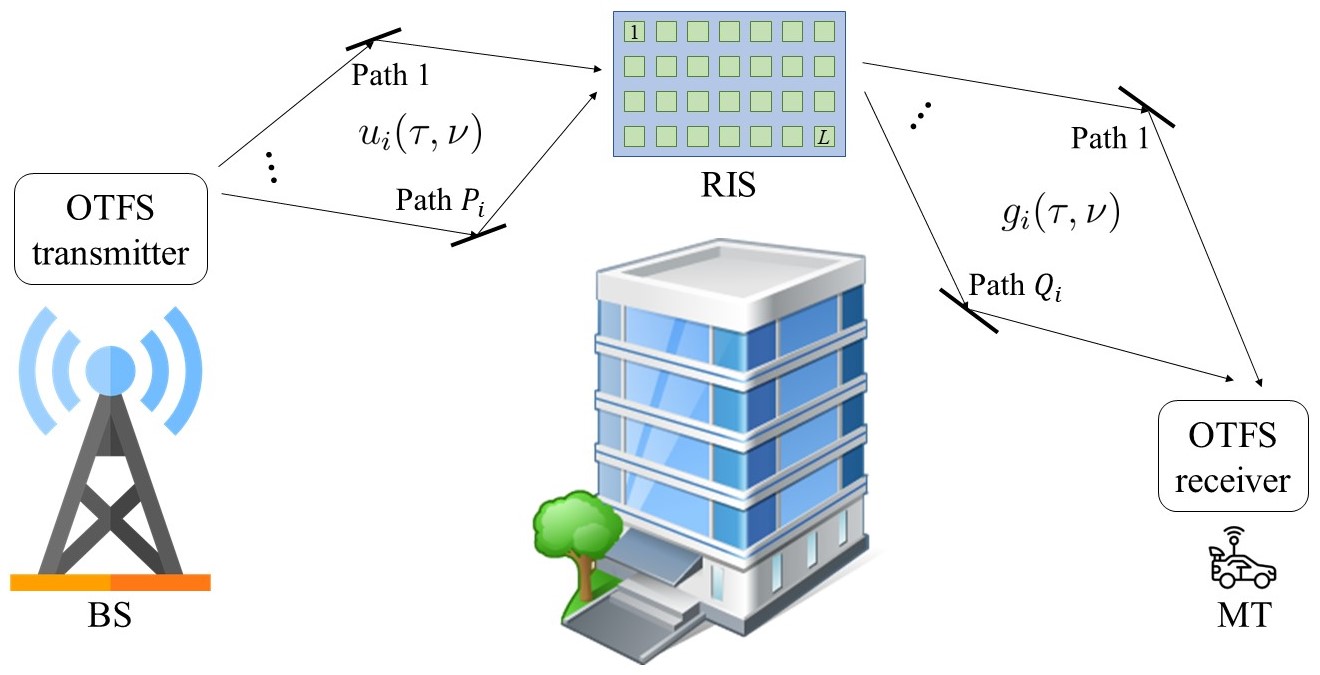
Fig. 1 illustrates an RIS-assisted OTFS system. In this scenario, we examine a downlink communication setup where a BS and a high-speed MT, both equipped with a single antenna, communicate via an RIS. However, the direct link between the transmitter and the receiver is blocked by obstacles. Furthermore, we consider the time-division duplexing (TDD) scenario, while assuming perfect synchronization and knowledge of channel state information (CSI) at the transmitter and receiver. The RIS consists of reflecting elements whose phase shifts can be adjusted by the transmitter. The phase shifts vector of the RIS elements is denoted by .
We consider a passive RIS with lossless elements, i.e., for .
In an OTFS system, the transmit symbols are considered in the delay-Doppler (DD) domain. Suppose be the data symbol transmitted in the -th Doppler and -th delay bin where and . Therefore, the total number of symbols are placed on a uniform DD grid. First, the DD domain data symbols are transformed to the time-frequency (TF) domain through inverse symplectic finite Fourier transform (ISFFT) operation, i.e.,
where and are the time and frequency indices, respectively. The TF samples are uniformly spread in a uniform plane with a total duration of and a total bandwidth of . The time and frequency spacings between the samples are and , respectively. Then, the Heisenberg transform [3] is applied to the TF signal to obtain the time domain transmit signal .
Next, let the DD domain BS-RIS and RIS-MT channels for each RIS element be, respectively, represented as
| (1) |
| (2) |
where is the number of paths between the BS and RIS element , and , and are the path gain, delay time, and Doppler shift, respectively, corresponding to path ; while, is the number of paths between the -th RIS element and MT, and , and denote the path gain, delay time, and Doppler shift, respectively, associated with path . We consider the multipath channel gains and , respectively, distributed as and , with , and , for all .
The time domain signal travels through the BS-RIS channel. Hence, the received signal at RIS element is given by
| (3) |
Then, the reflected signal from RIS element is multiplied by coefficient . The resulting signal is then passed through the RIS-MT channel. Finally, the received signal at the MT is represented as
| (4) |
where is the additive white Gaussian noise (AWGN). By examining (4), we note that the cascaded RIS-assisted channel resembles a multipath channel consisting of total paths with the DD domain given by
| (5) |
where , , and . It is important to note that the cumulative delay times and Doppler shifts of cascaded paths are the summation of individual delay times and Doppler shifts. Meanwhile, the combined gain of successive paths is determined by multiplying individual gains, incorporating a phase shift that is related to the Doppler shift of the RIS-MT link and the delay time of the BS-RIS link. With this realization, we can leverage the results obtained for conventional OTFS systems without RIS. Hence, we can rewrite the received signal as
| (6) |
Using the Wigner transform [3] at the receiver the TF signal is obtained. Assuming bi-orthogonal transmit and receive pulses, then, by sampling the received TF signal at and , the discrete TF signal can be derived as [13]
| (7) |
where is the discrete noise signal at the TF bin independent and identically distributed (i.i.d.) as for all and . is the TF cascaded channel associated with RIS element that is given by [13]
Next, the TF domain signal is transformed to the DD domain by a symplectic finite Fourier transform (SFFT) operation, i.e.,
Hence, the DD domain input-output relationship can be expressed as [13, Eq. (20)]
| (8) |
where , , and . and represent the integer and fractional parts of the normalized Doppler shifts , respectively. Here, we consider integer delay shifts , which is a valid assumption in typical wideband systems.
Then, (8) can be represented in matrix form as
| (9) |
where are the vectored forms of and , respectively, such that and . is the cascaded DD domain channel matrix, and is the i.i.d. noise vector whose elements are with the same distribution as .
III Proposed Phase Shifts Design
In this section, we aim to adjust the phase shifts of the RIS elements to improve the performance of the OTFS. It is noteworthy that the majority of studies addressing RIS have predominantly focused on single-carrier scenarios for phase adjustment. Even in OFDM systems, where the entire bandwidth is taken into account, there has been a lack of consideration for channel aging in mobile scenarios. In contrast, this paper addresses the full bandwidth of an OTFS block and assumes fixed phase shifts of RIS elements during an OTFS time frame. Consequently, the channel variation in both time and frequency domains contribute to the phase adjustment.111It is worth noting that, similar to previous studies [6, 11, 12], we assume that the parameters of the DD domain channel remain relatively unchanged over a series of consecutive OTFS blocks while acknowledging variations from sample to sample. In light of this, taking into account the channel knowledge available at the transmitter, we aim to enhance the performance of the OTFS system by considering the signal-to-noise ratio (SNR) at the receiver, incorporating the Delay-Doppler (DD) channel. To this end, we propose an RIS phase adjustment technique that maximizes the received signal energy at the MT. Hence, the optimization problem can be defined as
| (10) |
where computes the Frobenius norm of a matrix. The solution for is not straightforward as it is a non-convex optimization problem. Hence, we adopt a gradient method to find an approximate solution to [14]. Algorithm 1 shows this gradient-based procedure. The gradient of needs to be computed to implement this algorithm. For this reason, we rewrite as
where , and is the Euclidean norm operator. To calculate the gradient of , we find its partial derivatives with respect to the complex conjugate of , i.e., based on Wirtinger calculus [15]. Hence, the gradient of can be expressed as
| (11) |
Next, the optimization problem at line 6 of Algorithm 1, which needs to be solved in each iteration, is given by
| s.t. | ||||
| where | (12) |
It is worth noting that as the main objective function in has a positive real value, we are interested in the real direction of the gradient. Hence, we consider the maximization of the real part in . Problem is still a non-convex problem due to the constraint; however, it can be transformed into a convex problem through relaxation, i.e., using the constraint for . Next, it can be proved that the optimal solution for the relaxed problem which is convex with the updated constraint, is given by
| (13) |
that is and . Therefore, problem can be solved by implementing the procedure presented in Algorithm 2. We establish a stopping criterion for the algorithm by setting a threshold condition , where is a design parameter.
Complexity Analysis
It can be realized that the main complexity of this algorithm lies at line 6, where the gradient needs to be computed at . Note that {} is a block-circulant (BC) matrix. Therefore, {} can be obtained by considering only the first columns of {}. As a result, initially, the complexity seems to be in the order of , i.e., , where is the number of iterations. However, considering the sparsity of {}, the number of non-zero elements in {} is far less than its length, verifying the low complexity of this algorithm. In other words, the complexity of this process is , where , and is the maximum number of non-zero elements in }, while is the number of nonzero elements in each row of . The equality occurs when all channels experience the same number of taps; in this case, the coincidence of nonzero elements in the vectorized channels } is the same for all .
IV Numerical Results
In this section, we demonstrate the performance of the RIS-assisted OTFS system through numerical analyses. First, we present the performance of the system across various scenarios, emphasizing the efficacy of the proposed phase shift design and optimization algorithm. Next, we conduct a comparison of the BER performance between the RIS-assisted OTFS system with the proposed phase shift design and benchmark schemes [11, 12]. These benchmarks consist of prominent RIS-assisted OTFS systems with the same configuration as this paper. Considering their notable improvements over OFDM systems, we find the comparison with OFDM scenarios unnecessary in this context. Without loss of generality, in our simulations, we consider the scenario where both the BS and RIS are fixed at high elevations. Hence, it is assumed that all multipath channels in the BS-RIS link experience the same number of paths with the same delay time and without Doppler effects; while the MT is relatively far from the RIS, such that the multipath channels between them experience the same number of paths with the same delay, but different Doppler taps. In addition, at the receiver, we deploy the minimum mean square error (MMSE) for all scenarios, while assuming the CSI available at the receiver.
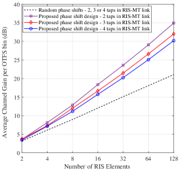
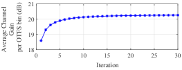
Fig. 2 shows the average channel gain in an RIS-assisted OTFS system with Doppler bins and subcarriers, where the phase shifts of the RIS elements are designed based on Algorithm 2. In addition, we consider four delay taps in the BS-RIS link with equal average gain power, while we present the results for various numbers of delay and Doppler taps in the RIS-MT link that are randomly selected with equal average gain power. Certainly, increasing the number of RIS elements noticeably improves the effective gain of the RIS-assisted channel, specifically when the phase shifts are properly adjusted. It can be observed that the RIS with the proposed phase shift design remarkably enhances the performance of the system and verifies the strength of the optimization algorithm. For example, the system with optimized phase shifts improves the performance by approximately 10 dB compared with the system with random phase shifts, in the scenario with four taps. This superiority increases for scenarios with less number of taps. In addition, the RIS with random phase shifts can enhance the channel gain by 3 dB with increasing the number of RIS elements by a factor of 2. Meanwhile, by the proposed phase design, the channel gain can be improved by approximately 6 dB, where the number of RIS elements is relatively large. These results are in accordance with the results obtained in RIS-assisted schemes for single carrier systems in time-invariant channels [16]. Additionally, it is noted that when employing a random phase configuration, the received energy remains independent of the number of taps. However, by implementing adjusted phase shifts, further enhancement is achieved as the number of taps decreases. This is because the RIS can more efficiently target a smaller number of taps (paths). It is noted that increasing bandwidth leads to a higher number of taps. According to this observation, the efficacy of the RIS is subsequently reduced. Moreover, to validate the efficacy of the proposed algorithm, we illustrate its convergence rate in Fig. 3. The graph demonstrates that the algorithm’s output approaches approximately 97% of the optimum value after just 10 iterations, confirming the rapid convergence of the proposed algorithm.
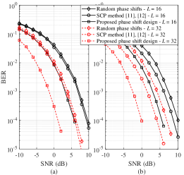
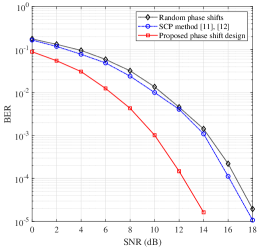
Next, in Fig. 4, we illustrate the BER performance of the RIS-assisted OTFS system and compare the results with that of the benchmark schemes. For benchmark, we consider RIS-assisted OTFS systems in [11, 12], where only the strongest cascaded path (SCP) was considered for phase shift adjustment. In all scenarios, we use channels with four taps in both links and consider the system with , , and 4-QAM modulation. In addition, the maximum number of iterations and are set to be 15 and , respectively, for the proposed algorithm to design the phase shifts. Fig. 4(a) shows the BER results in a channel with equal average tap gains. We observe that our proposed phase shift design significantly enhances the performance of the system. In contrast, adjusting the phase shifts based on the SCP method does not result in a considerable improvement over random phase shifts. To have a fair comparison with the SCP method which considers a single strong tap, in Fig. 4(b), we consider the channel with unequal average tap gains for both BS-RIS and RIS-MT links, such that 70 percent of the channel gain in each link is dedicated to a single tap. By observing Fig. 4(b), we realize that the SCP method can moderately improve the BER performance, however, the proposed solution can leverage the enhancement more significantly. For instance, when our proposed technique is utilized, approximately 4 dB and 7 dB performance gains are achieved, respectively, compared with the SCP method in [11, 12], and random phase shifts at the BER of , where 32 RIS elements are deployed. This superiority over the benchmarks is due to the fact that the SCP method only targets a single tap; hence, the RIS is unable to efficiently reflect the energy of the other taps toward the receiver. Although SCP uses a low-complexity algorithm, it cannot provide superior performance and presents even a small improvement if there exist multiple taps with the same energy. In contrast, the proposed phase shift design collects the energy of all available taps and considers the channel variation caused by Doppler effects. In addition, it can be observed that increasing the number of RIS elements from 16 to 32, enhances the performance of the system with random phase shifts by 3 dB and the system using the SCP method by 4.3 dB, while the enhancement is around 6 dB for our proposed technique. This reveals that the superiority over the benchmark schemes dramatically increases with increasing the number of RIS elements.
Finally, to showcase the performance in a standard channel scenario, in Fig. 5 we present the BER performance results in the tapped delayed line (TDL) channel model, denoted by TDL-C [17], provided by 3rd generation partnership project (3GPP). In this scenario, we consider a system with Doppler bins, frequency subcarriers, and RIS elements, where the carrier frequency and subcarrier spacing are 4 GHz and 15 kHz, respectively. The MT speed is assumed to be 500 km/h. As expected, we observe the same trend as seen in Fig. 4(a). This is because, with the aforementioned configuration, two taps possess approximately equal average energy, and the SCP method can only target one of them. That is, the SCP method cannot efficiently improve the performance, while the system with the proposed phase shift design outperforms the SCP method by approximately 4 dB at the BER of .
V Conclusion
This paper investigated the integration of RIS with OTFS modulation to enhance high-speed wireless communications. We presented the characterization of the cascaded channel and provided the input-output relation considering the cascaded delay-Doppler channel response. A phase shift design algorithm was proposed which maximizes the energy at the receiver by collecting the energy of all taps in the whole OTFS time frame while considering the time-varying property of the channel. Moreover, comprehensive numerical analyses showcase the system’s performance improvements. Results indicate that the proposed approach significantly enhances the system’s performance compared to benchmark schemes, particularly achieving more than 4 dB gain over them. The findings underscore the potential of this integrated approach for advancing the capabilities of wireless communication systems, particularly in high-speed and dynamic environments.
References
- [1] M. Di Renzo et al., “Smart radio environments empowered by reconfigurable intelligent surfaces: How it works, state of research, and the road ahead,” IEEE J. Sel. Areas Commun., vol. 38, pp. 2450–2525, Nov. 2020.
- [2] M. H. Dinan, N. S. Perović, and M. F. Flanagan, “RIS-assisted receive quadrature space-shift keying: A new paradigm and performance analysis,” IEEE Trans. Commun., vol. 70, pp. 6874–6889, Oct. 2022.
- [3] R. Hadani, S. Rakib, M. Tsatsanis, A. Monk, A. J. Goldsmith, A. F. Molisch, and R. Calderbank, “Orthogonal time frequency space modulation,” in IEEE Wireless Commun. Netw. Conf. (WCNC), pp. 1–6, 2017.
- [4] T. Thaj and E. Viterbo, “Low complexity iterative rake decision feedback equalizer for zero-padded OTFS systems,” IEEE Trans. Veh. Technol., vol. 69, pp. 15606–15622, Dec. 2020.
- [5] P. Raviteja, Y. Hong, E. Viterbo, and E. Biglieri, “Effective diversity of OTFS modulation,” IEEE Wireless Commun. Lett., vol. 9, pp. 249–253, Feb. 2020.
- [6] G. Harshavardhan, V. S. Bhat, and A. Chockalingam, “RIS-aided OTFS modulation in high-Doppler channels,” in IEEE 33rd Annu. Int. Symp. Pers., Indoor, Mobile Radio Commun. (PIMRC), pp. 409–415, 2022.
- [7] V. S. Bhat, G. Harshavardhan, and A. Chockalingam, “Input-output relation and performance of RIS-aided OTFS with fractional delay-Doppler,” IEEE Commun. Lett., vol. 27, pp. 337–341, Jan. 2023.
- [8] M. Li, S. Zhang, Y. Ge, F. Gao, and P. Fan, “A novel transmission strategy for hybrid RIS aided millimeter wave OTFS systems,” in 14th Int. Conf. Wireless Commun. Signal Process., pp. 1058–1063, 2022.
- [9] M. Li, S. Zhang, Y. Ge, F. Gao, and P. Fan, “Joint channel estimation and data detection for hybrid RIS aided millimeter wave OTFS systems,” IEEE Trans. Commun., vol. 70, pp. 6832–6848, Oct. 2022.
- [10] Z. Li, W. Yuan, B. Li, J. Wu, C. You, and F. Meng, “Reconfigurable-intelligent-surface-aided OTFS: Transmission scheme and channel estimation,” IEEE Internet Things J., vol. 10, pp. 19518–19532, Nov. 2023.
- [11] A. S. Bora, K. T. Phan, and Y. Hong, “IRS-assisted high mobility communications using OTFS modulation,” IEEE Wireless Commun. Lett., vol. 12, pp. 376–380, Feb. 2023.
- [12] A. Thomas, K. Deka, S. Sharma, and N. Rajamohan, “IRS-assisted OTFS system: Design and analysis,” IEEE Trans. Veh. Technol., vol. 72, pp. 3345–3358, Mar. 2023.
- [13] P. Raviteja, K. T. Phan, Y. Hong, and E. Viterbo, “Interference cancellation and iterative detection for orthogonal time frequency space modulation,” IEEE Trans. Wireless Commun., vol. 17, pp. 6501–6515, Oct. 2018.
- [14] M. Journée, Y. Nesterov, P. Richtárik, and R. Sepulchre, “Generalized power method for sparse principal component analysis,” J. Mach. Learn. Res., vol. 11, pp. 517–553, Dec. 2010.
- [15] R. F. Fischer, Precoding and Signal Shaping for Digital Transmission. New York, NY, USA: John Wiley & Sons, 2002.
- [16] M. H. Dinan, M. D. Renzo, and M. F. Flanagan, “RIS-assisted receive quadrature spatial modulation with low-complexity greedy detection,” IEEE Trans. Commun., vol. 71, pp. 6546–6560, Nov. 2023.
- [17] 5G; Study on channel model for frequencies from 0.5 to 100 GHz, document 3GPP TR 38.901, version 17.0.0, Release 17, European Telecommunications Standards Institute, Apr. 2022.