Integrated Sensing and Communication Under DISCO Physical-Layer Jamming Attacks
Abstract
Integrated sensing and communication (ISAC) systems traditionally presuppose that sensing and communication (S&C) channels remain approximately constant during their coherence time. However, a “DISCO” reconfigurable intelligent surface (DRIS), i.e., an illegitimate RIS with random, time-varying reflection properties that acts like a “disco ball,” introduces a paradigm shift that enables active channel aging more rapidly during the channel coherence time. In this letter, we investigate the impact of DISCO jamming attacks launched by a DRIS-based fully-passive jammer (FPJ) on an ISAC system. Specifically, an ISAC problem formulation and a corresponding waveform optimization are presented in which the ISAC waveform design considers the trade-off between the S&C performance and is formulated as a Pareto optimization problem. Moreover, a theoretical analysis is conducted to quantify the impact of DISCO jamming attacks. Numerical results are presented to evaluate the S&C performance under DISCO jamming attacks and to validate the derived theoretical analysis.
Index Terms:
Integrated sensing and communication, reconfigurable intelligent surface, physical-layer security, channel aging, Pareto optimization.I Introduction
Integrated sensing and communication (ISAC) is a promising candidate technology for future sixth generation (6G) wireless communication systems and has attracted increasing attention. In particular, ISAC implements joint target sensing and data communication using the same RF hardware and computing platform [1, 2], offering an exciting opportunity to implement sensing using traditional wireless communication infrastructure [3]. The added sensing functionality enabled by the collection of environmental data makes ISAC a fundamental component of future smart envionrments. In particular, ISAC is applicable to vehicle-to-everything communications, smart homes, and smart manufacturing. There has been considerable research on ISAC-related problems, including ISAC waveform design [4, 5]. Considering the difficulties of optimization problems involving the mean squared error (MSE) or the Cramr-Rao lower bound (CRLB), most existing works use simpler alternative optimization criteria such as the transmit beampattern [6, 4, 5].
Recently, reconfigurable intelligent surfaces (RISs) are also anticipated to play a critical role in future 6G wireless communications. These surfaces are embedded with many elements whose reflection coefficients can be tuned by simple programmable PIN or varactor diodes [7, 8, 9], By properly tuning these reflection coefficients, the electromagnetic environment can be reshaped to enhance signal transmission to improve both sensing and communication (S&C) [6, 10]. However, the S&C performance enhancement relies on the basic premise that the S&C channels are approximately constant during the channel coherence time. This basic premise is normally valid, but can be negated when so-called DISCO RISs (DRISs) are deployed [11].
The idea of DRISs was first introduced in the DRIS-based fully-passiver jammer (FPJ) [12], where the DRIS with time-varying reflection properties acts like a “disco ball.” The DRIS hence introduces active channel aging (ACA), and thus the wireless channels will vary more rapidly than the channel coherence time [12, 13, 14]. Such ACA can be used to jam communication users or degrade the accuracy of target sensing without the use of either jamming power or channel state information (CSI). This type of ACA interference (ACAI) is referred to as a DISCO jamming attack, and renders the above basic premise for ISAC systems invalid.
In this work, we aim to characterize the impact of DISCO jamming attacks on ISAC systems. To the best of our knowledge, this is the first time that the validity of the basic premise has been investigated for ISAC systems. The main contributions are summarized as follows:
-
•
A DRIS-based FPJ is introduced into an ISAC system to launch DISCO jamming attacks. Furthermore, a practical RIS model is considered in the DRIS-based FPJ, where the DRIS phase shifts of the reflective elements are discrete and the DRIS amplitudes are a function of their corresponding phase shifts.
-
•
In the ISAC waveform design model, the desired sensing waveform and the signal-to-interference-plus-noise ratio (SINR) are used as S&C performance metrics. Consequently, the ISAC waveform design problem under DISCO jamming attacks is formulated as a Pareto optimization problem. We present a corresponding ISAC waveform design by considering the trade-off between the S&C performance metrics.
-
•
We show that the DISCO jamming attacks force the sensing detection to shift from unbiased to biased estimation and impair the communication sum rate. Moreover, a theoretical analysis is performed to quantify the impact of the DISCO jamming attacks.
Notation: We employ bold capital letters for a matrix, e.g., , lowercase bold letters for a vector, e.g., , and italic letters for a scalar, e.g., . The superscripts and represent the transpose and the Hermitian transpose, respectively, and the symbols and represent the Frobenius norm and the absolute value, respectively.
II System Description
In this section, we first illustrate DISCO jamming attacks launched by a DRIS-based FPJ in Section II-A. Then, the model of the ISAC system under DISCO jamming attacks is given in Section II-B.
II-A DRIS-Based Active Channel Aging
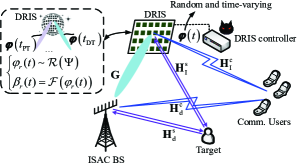
Fig. 1 shows an ISAC system under DISCO jamming attacks launched by a DRIS-based FPJ [12]. The DRIS with reflective elements is implemented using PIN diodes, whose ON/OFF behavior only allows for discrete phase shifts. Therefore, the time-varying DRIS phase shifts ( are randomly selected from a discrete set with -bit quantized values and follow a stochastic distribution denoted as . The corresponding time-varying amplitude is a function of and represented by , where . As a result, the time-varying DRIS reflecting vector is given by .
In traditional wireless systems, the wireless channels are assumed to be fixed during the channel coherence time. Consequently, the CSI estimated during the pilot transmission (PT) phase can be used to design the waveform used in the remaining data transmission (DT) phase of each channel coherence time. Before S&C data transmission, the ISAC base station (BS) first learns the CSI during the PT phase via existing methods such as the least square (LS) algorithm. Mathematically, the CSI111We assume that perfect CSI is available as imperfect CSI is not a primary concern in the jamming scenario, and its impact has been thoroughly studied [15]. estimated during the PT phase is written as
| (1) |
where and represent the direct channel and the time-varying DRIS-jammed channel between the ISAC BS and the communication users, respectively.
Due to the random and time-varying DRIS reflecting coefficients, ACA is introduced within the channel coherence time. The time between changes in the DRIS reflection coefficients is typically assumed to be about the same as the length of the PT phase [11, 14]. As a result, the DRIS rapidly ages the wireless channels, and effectively produces a channel with coherence interval approximately equal to the PT phase. Mathematically, the ACA channel during the DT phase can be represented as
| (2) |
where and denote the channel between the ISAC BS and the DRIS and the channel between the DRIS and all communication users.
II-B ISAC Under DISCO Jamming
Communication Model: In Fig. 1, the ISAC BS is equipped with transmit antennas to communicate with single-antenna communication users. During the DT phase, the ISAC BS transmits symbols to these users, and thus the length of the data frame is . Consequently, the received symbols at the users are expressed as
| (3) |
where denotes the desired constellation symbol matrix, represents the transmitted signal matrix used as the ISAC waveform for both the communication and the sensing functions [4, 5], and is a Gaussian noise matrix composed of independent and identically distributed (i.i.d.) elements with zero mean and variance , i.e., . Based on (3), we can see that the DRIS-based FPJ imposes ACAI on the signals in addition to multi-user interference (MUI) [4, 16]. Referring to [13, 4, 16], the SINR at the -th user is given by
| (4) |
Consequently, the sum rate can be computed based on (4), i.e., .
Sensing Model: To quantify the sensing performance, we use the quality of the estimated target angle [17]. More specifically, the symbols are reflected by the target and then received at the ISAC BS, which are expressed as [10]
| (5) |
where is the reflection cross-section of the target, , , and are the round-trip large-scale channel fading coefficients of the direct sensing path and the time-varying DRIS-jammed sensing path, is an noise matrix whose i.i.d. elements have zero mean and variance , and is the time-varying DRIS-jammed sensing vector, i.e.,
| (6) |
In (5) and (6), the steering vectors of the ISAC BS antenna array and the DRIS are respectively defined as
| (7) |
and
| (8) |
where denotes the array spacing normalized by the wavelength, and represents the Kronecker product.
To estimate , we exploit the MUSIC algorithm [18]. Consequently, the sample covariance matrix computed based on snapshots is
| (9) |
and the MUSIC spectral function is then computed from . However, based on (5), the DRIS-induced biases are introduced into , which impairs the location of the spectral peak in , which leads to a biased DoA estimation.
To achieve the best target detection performance, the ISAC waveform should satisfy
| (10) |
where is the total transmit power at the ISAC BS and is an identity matrix. Without loss of generality, we assume to ensure that is positive-definite.
III ISAC Waveform Design Under DISCO Jamming
In this section, we first formulate the ISAC waveform design problem under DISCO jamming attacks described in Section III-A. Then, we give a waveform optimization design for the ISAC system under these attacks in Section III-B. In Section III-C, a theoretical analysis is derived to quantify the impact of DISCO jamming attacks.
III-A Problem Formulation
According to (3) and (4), the optimum ISAC waveform should be designed to minimize the power of the MUI and ACAI. However, due to the time-varying and random DRIS reflecting vector , the ISAC BS can not obtain . Therefore, we consider designing the ISAC waveform by minimizing the MUI. Mathematically, the ISAC waveform design problem is formulated as
| (11) | ||||
The strict equality constraint (10) ensures that the ISAC waveform has the same properties as the best sensing waveform, although the communication performance may be degraded as a result [4]. Therefore, there should be a trade-off between the sensing capability and the communication rate in so we introduce a trade-off factor () into . Denoting the solution to as , the following Pareto optimization problem can be obtained:
| (12) | ||||
| (13) |
For different , the solution to makes different trade-offs between S&C performance. More specifically, the smaller the , the better the sensing performance, but the worse the communication performance.
III-B ISAC Waveform Design
In order to solve , we first compute from . However, is a non-convex problem. Fortunately, [19] has pointed out that is a classical orthogonal Procrustes problem. As a result, a simple closed-form solution to can be obtained based on the singular value decomposition (SVD), i.e.,
| (14) |
where and are the left and right singular value matrices of and satisfy .
Before solving , we transform it into the following form using the approach of [4],
| (15) | ||||
where and .
Although is a non-convex quadratically constrained quadratic programming (QCQP) problem, it can be transformed into a semidefinite programming (SDP) problem using semidefinite relaxation (SDR). Moreover, has only one quadratic constraint, i.e., (13). Therefore, the rank-1 SDR solution is its globally optimal solution.
III-C Impact of DISCO Jamming Attacks
For a given ISAC waveform, the sum rate is affected not only by the MUI due to sensing functionality considerations, but also by the ACAI. The impact of MUI has been investigated in some existing literature, such as [4, 5] so we focus on the impact of the ACAI imposed by the DRIS-based FPJ. For ease of presentation, we rewrite the interference term in (4) as
| (16) |
The DRIS must be equipped with a large number of reflective elements to overcome the multiplicative propagation loss in the DRIS-jammed channels. Based on the work in [14], the elements of have the statistical characteristics outlined in Proposition 1.
Proposition 1
The elements of converge in distribution to as , i.e.,
| (17) |
where is the large-scale channel fading coefficient of the DRIS-jammed channel between the ISAC BS and the -th communication user, , , , , , and are the probabilities of the random phases .
Proof:
See [14]. ∎
Theorem 1
Under DISCO jamming attacks launched by the DRIS-based FPJ, the lower bound of the SINR received at the -th communication user for any ISAC waveform computed from converges in distribution to
| (18) |
Proof:
Since the ISAC waveform computed from is optimized only based on , we can assume that is independent of the communication ACA channel . Consequently, the expectation of in (16) is
| (19) |
IV Simulation Results and Discussion
We consider an ISAC system equipped with a 16-element antenna array is located at (0m, 0m, 3m) and jammed by the DRIS-based FPJ. The ISAC BS communicates with 8 single-antenna users that are randomly distributed in the circular region centered at (0m, 180m, 0m) with a radius of 20m. The DRIS with 1024 () reflective elements is deployed at (2m, 0m, 2m) to launch DISCO physical-layer jamming attacks. We assume that the DRIS has one-bit quantized phase shifts and gain values taken from and [8], and the two phase shifts are chosen with equal probability. Consequently, in Theorem 1 is 1.6078. The length of the data frame is and the trade-off factor in is .
Based on the settings above, the wireless channel is constructed using a near field channel model, while the wireless channels and are both based on far field channel models [14, 13, 12, 17]. The large-scale line-of-sight (LoS) and non-line-of-sight (NLoS) channel fading coefficients are defined in Table I based on 3GPP propagation models [20], and the variance of the noise is dBm with a transmission bandwidth of 180 KHz.
| Parameter | Value |
|---|---|
| Large-scale LoS fading | (dB) |
| Large-scale NLoS fading |
Fig. 2 illustrates the results obtained by the following approaches: 1) the sum rate obtained based on (4) without MUI or ACAI (Theoretical ISAC Up-Bound); 2) the sum rate achieved by a traditional ISAC system [4] (T-ISAC W/ in [4]); 3) the sum rate achieved by an ISAC system under DISCO jamming attacks, i.e., (Proposed T-ISAC W/ DISCO); 4) the theoretical analysis of Proposed T-ISAC W/ DISCO based on Theorem 1 (Theoretical T-ISAC W/ DISCO); 5) the sum rate achieved by a traditional ISAC system [4] with the strict equality constraint (10) (S-ISAC in [4]); 6) the sum rate achieved by an ISAC system under DISCO jamming attacks and the strict equality constraint (10), i.e., (Proposed S-ISAC W/ DISCO); 7) the theoretical analysis of Proposed S-ISAC W/ DISCO based on Theorem 1 (Theoretical S-ISAC W/ DISCO).
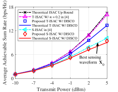
We can see from Fig. 2 that by considering the trade-off between the S&C performance the gap between Theoretical ISAC Up-Bound and T-ISAC W/ in [4] is small. In other words, the sum rate is not seriously affected by the sensing functionality when the ISAC waveform is well designed. However, the performance is severely compromised by DISCO jamming attacks. Moreover, the results of Proposed T-ISAC W/ DISCO and Proposed S-ISAC W/ DISCO are very close to the ideal lower-bounded performance of Theoretical T-ISAC W/ DISCO and Theoretical S-ISAC W/ DISCO.
Based on Theorem 1, the impact of DISCO jamming attacks on the sum rate can be quantified by . To evaluate the validity of Theorem 1, the relationship between the sum rate and the number of DRIS reflective elements is given in Fig. 3. We can see that the sum rate decreases with the number of DRIS elements , and the achieved sum rates for different are close to the theoretical lower bound.
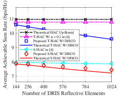
Fig. 4 shows the impact of the ISAC waveform and the DISCO jamming attacks on the sensing performance. We assume that the echo SNR from the direct sensing path is 35 dB. We denote the spectral functions obtained from the best sensing waveform without DISCO jamming attacks, the best sensing waveform under DISCO jamming attacks, and the ISAC waveform obtained from as , , and , respectively. The loss of spectral function peaks [5, 17] between and is displayed by the red diamond (Impact of DISCO), and that between and is plotted by the blue “+” symbol (Impact of DISCO and ISAC).
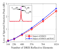
Fig. 4 illustrates that DISCO jamming attacks impair the sensing performance of the MUSIC algorithm. Based on (5), the DRIS-based FPJ introduces an extra interference term into the received echo signals compared to the traditional ISAC system [4, 5]. In other words, the DISCO jamming results in a biased DoA estimate, and the resulting impact on the sensing performance also increases with the number of DRIS reflective elements.
V Conclusions
In this letter, we have investigated the trade-off between the S&C performance in ISAC systems under DISCO jamming attacks. The ISAC waveform design was formulated as a Pareto optimization problem with a trade-off factor. The CSI during the channel coherence time is no longer fixed due to the ACA introduced by the DRIS-based PFJ. We quantified the impact of DISCO jamming attacks on the sum rate for any given ISAC waveform. In addition, the DISCO jamming leads to biased DoA estimation, which in turn degrades the sensing performance of the system. The amount of the bias can be increased by increasing the number of DRIS reflective elements. To characterize the sensing performance degradation due to the DRIS-induced biases, a theoretical analysis based on the CRLB will be conducted in our future work.
References
- [1] H. Zhang, H. Zhang, B. Di, and L. Song, “Holographic integrated sensing and communications: Principles, technology, and implementation,” IEEE Commun. Mag., vol. 61, no. 5, pp. 83–89, May 2023.
- [2] J. A. Zhang, et al., “Integration of radar sensing into communications with asynchronous transceivers,” IEEE Commun. Mag., vol. 60, no. 11, pp. 106–112, Nov. 2022.
- [3] F. Liu, Y. Cui, C. Masouros, J. Xu, T. X. Han, Y. C. Eldar, and S. Buzzi, “Integrated sensing and communications: Toward dual-functional wireless networks for 6G and Beyond,” IEEE J. Sel. Areas Commun., vol. 40, no. 6, pp. 1728–1767, Jun. 2022.
- [4] F. Liu, et al., “Toward dual-functional radar-communication systems: Optimal waveform design,” IEEE Trans. Signal Process., vol. 66, no. 16, pp. 4264–4279, Aug. 2018.
- [5] F. Liu, C. Masouros, A. Li, H. Sun, and L. Hanzo, “MU-MIMO communications with MIMO radar: From co-existence to joint transmission,” IEEE Trans. Wireless Commun., vol. 17, no. 4, pp. 2755–2770, Apr. 2018.
- [6] R. Liu, M. Li, H. Luo, Q. Liu, and A. L. Swindlehurst, “Integrated sensing and communication with reconfigurable intelligent surfaces: Opportunities, applications, and future directions,” IEEE Wireless Commun., vol. 30, no. 1, pp. 50–57, Feb. 2023.
- [7] T. Cui, M. Qi, X. Wan, J. Zhao, and Q. Cheng, “Coding metamaterials, digital metamaterials and programmable metamaterials,” Light-Sci. Appl., vol. 3, e218, Oct. 2014.
- [8] H. Zhang, S. Zeng, B. Di, Y. Tan, M. D. Renzo, M. Debbah, Z. Han, H. V. Poor, and L. Song, “Intelligent omni-surfaces for full-dimensional wireless communications: Principles, technology, and implementation,” IEEE Commun. Mag., vol. 60, no. 2, pp. 39–45, Feb. 2022.
- [9] W. Mei, B. Zheng, C. You, and R. Zhang, “Intelligent reflecting surface aided wireless networks: From single-reflection to multi-reflection design and optimization,” Proc. IEEE, vol. 110, no. 9, pp. 1380–1400, Sep. 2022.
- [10] Z. Wang, X. Mu, and Y. Liu, “STARS enabled integrated sensing and communications,” IEEE Trans. Wireless Commun., vol. 22, no. 10, pp. 6750–6767, Oct. 2023.
- [11] H. Huang, et al., “DISCO might not be funky: Random intelligent reflective surface configurations that attack,” arXivpreprint arXiv:2310.00687, Oct. 2023.
- [12] H. Huang, Y. Zhang, H. Zhang, C. Zhang, and Z. Han, “Illegal intelligent reflecting surface based active channel aging: When jammer can attack without power and CSI,” IEEE Trans. Veh. Technol., vol. 72, no. 8, pp. 11018–11022, Aug. 2023.
- [13] H. Huang, Y. Zhang, H. Zhang, Y. Cai, A. L. Swindlehurst, and Z. Han, “Disco intelligent reflecting surfaces: Active channel aging for fully-passive jamming attacks,” IEEE Trans. Wireless Commun., vol. 23, no. 1, pp. 806–819, Jan. 2024.
- [14] H. Huang, L. Dai, H. Zhang, Z. Tian, Y. Cai, C. Zhang, A. L. Swindlehurst, and Z. Han, “Anti-jamming precoding for disco intelligent reflecting surfaces based fully-passive jamming attacks,” IEEE Trans. Wireless Commun., early access, Feb. 2024, doi: 10.1109/TWC.2024.3360728.
- [15] T. X. Tran and K. C. Teh, “Spectral and energy efficiency analysis for SLNR precoding in massive MIMO systems with imperfect CSI,” IEEE Trans. Wireless Commun., vol. 17, no. 6, pp. 4017–4027, Jun. 2018.
- [16] S. K. Mohammed and E. G. Larsson, “Per-antenna constant envelope precoding for large multi-user MIMO systems,” IEEE Trans. Commun., vol. 61, no. 3, pp. 1059–1071, Mar. 2013.
- [17] Z. Wang, X. Mu, Y. Liu, “Near-field integrated sensing and communications,” IEEE ommun. Lett., vol. 27, no. 8, pp. 2048–2052, Aug. 2023.
- [18] R. Schmidt, “Multiple emitter location and signal parameter estimation,” IEEE Trans. Antennas Propag., vol. 34, no. 3, pp. 276 –280, Mar. 1986.
- [19] T. Viklands, “Algorithms for the weighted orthogonal Procrustes problem and other least squares problems,” Ph.D. dissertation, Comput. Sci. Dept., Umea Univ., Umea, Sweden, 2008.
- [20] Further Advancements for E-UTRA Physical Layer Aspects (Release 9), document 3GPP TS 36.814, Mar. 2010.