Current Affairs: A Measurement Study of Deployment and Security Trends in EV Charging Infrastructure
Abstract.
The deployment of electric vehicle charging infrastructure is occurring at a rapid pace. Simultaneously, existing standards, such as ISO 15118, which defines critical charging communication, are being improved and further developed.
In this paper, we conduct a measurement study of already deployed DC charging stations to analyze the current state of deployment for various protocols. We present the adoption of TLS, and various EV charging protocols with a direct security impact, as well as observations about the Signal Level Attenuation Characterization (SLAC) process, and encryption keys.
Our results indicate that even recently installed charging stations (December 2023) do not adhere to the latest version of the standard, leaving them vulnerable to attacks. We found that 84% of the surveyed charging stations do not implement Transport Layer Security (TLS), and are thus unable to implement the latest versions of the ISO 15118 protocol, leaving them vulnerable to attacks already demonstrated years ago. Finally, we observe and document anomalous behavior and violations of the standard.
1. Introduction
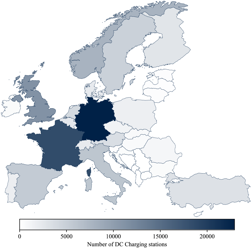
The deployment of Electric Vehicle (EV) charging infrastructure is happening at a rapid pace. In 2023 alone, around 185,000 public AC and DC charging stations have been installed within the European Union, which corresponds to a growth of 41% (eu_alternative_fuels_observatory, ). Figure 1 shows the current deployment state of fast and rapid chargers within Europe. Given the rapid adoption, the widespread deployment of high-capacity charging parks, and the increasing reliance on EVs in critical applications such as supply chains, coupled with bi-directional charging for grid stability, the security of EV charging infrastructure has become a focal point for the security community. Over the years, EV charging technologies have been studied from a security and privacy perspective and recommendations to improve the next generation of standards have been made (baker2019losing, ; kohler2023brokenwire, ; conti2022evexchange, ; bao2017threat, ; fries2012electric, ; antoun2020detailed, ).
In parallel to the deployment of new Electric Vehicle Supply Equipment (EVSE), manufacturers and standardization bodies, such as CharIN e.V. and the International Standards Organization (ISO), work on improving current charging standards to optimize the power delivery, safety and security. In an effort to consolidate the various charging technologies, a few standards have emerged and are gaining widespread adoption. The 4 most popular technologies used for high power EV charging are the Combined Charging System (CCS), North American Charging Standard (NACS) formerly the Tesla connector, CHAdeMO and GB/T. Out of these, CCS has the most widespread adoption, with significant deployment in North America, Europe and parts of Asia. The European Union legally requires high-powered DC charging to offer CCS (ccs_law, ), and the US government only supports charging infrastructure projects that offer CCS (us_nevi, ). In addition, modern NACS is technologically identical to CCS, differing only in the shape of the connector.
CCS is not a singular standard, but rather a collection of standards, with different versions and capabilities.
Newer versions introduce both additional features and security mechanisms.
The system is intended to allow most reasonable vehicles and chargers to interoperate, with or without additional advanced features depending on their individual age and capabilities.
This means that real world of CCS deployments is a rich tapestry of different versions.
In this paper, we present the first large-scale study that investigates the deployment state of the different CCS implementation versions.
We consider our work to be a valuable contribution to the EV security research community, aimed at better understanding the current deployment landscape and estimating the impact of newly discovered vulnerabilities.
More specifically, we make the following contributions:
-
•
We developed a car simulator that enabled us to test 105 already deployed CCS EV charging stations across the United Kingdom.
-
•
We analyzed the support for different versions of the standard and the support of security features, such as encrypted communication.
-
•
We showed that 84% of the surveyed charging stations do not implement Transport Layer Security, leaving them vulnerable to various attacks.
-
•
We found that some charging stations violate the standard and exhibit anomalies.
2. Background
The Combined Charging System (CCS) is a standard for charging electric vehicles that integrates different charging methods into a single, universal system. While often associated with DC fast charging, the standard also defines a modern version of AC charging, as well as bidirectional power transfer. In addition, it extends beyond the minimum communication required for safe power transfer to offer convenient features such as Plug and Charge, where the EV can negotiate payment without user interaction, or scheduled charging, which takes advantage of variable electricity prices.
Unlike other standards, CCS is not released as a comprehensive standards document, but instead as a collection of implementation notes by CharIN e.V. (charin_ccs, ), a non-profit association composed of different stakeholders, such as car manufacturers, suppliers and charging station vendors. They define CCS to be a combination of other standards: they use the IEC 62196-2 (std_IEC_62196_2, ) Type 1 and Type 2 connectors for AC, IEC 62196-3 (std_IEC_62196_3, ) Combo 1 and Combo 2 connectors for DC, depending on the region. On top of these, Basic CCS uses DIN SPEC 70121 (std_DIN_70121, ), while newer versions of CCS use ISO 15118 (std_ISO_15118_3, ; std_ISO_15118_2, ) for communication. While each different version introduces new features and makes changes, the core technologies are largely identical, and some aspects can be traced back to the SAE J1772 (std_SAE_J1772, ) standard for AC charging, beginning in 1996. In this section we present a technical description of a general CCS implementation based on (std_ISO_15118_3, ; std_ISO_15118_2, ), followed by a comparison of the new features introduced by different versions.
2.1. Technical Description
A CCS charging session can be divided into 4 key sections: Basic Signaling, Matching, Service Discovery and Vehicle-to-Grid communication.
| State | Pilot High | Load [] | EV Status |
| Ax | 12 | N/A | Not connected |
| Bx | 9 | 2740 | Connected |
| Cx | 6 | 882 | Ready for power |
| Dx | 3 | 246 | With ventilation |
| State | Pilot Low | PWM Duty | Charger Status |
| X1 | N/A | 100% | Idle |
| X2 | -12 | 5% | Need HLC |
| Not -12 | ¡100% | EV Error | |
| State | Pilot Level | Charger Status | |
| E | 0 | No Power | |
| F | -12 | Error |
Basic Signaling: All physical CCS connectors contain three common pins, referred to as the Proximity Pilot (PP), Control Pilot (CP) and Protective Earth (PE). The PP pin allows the vehicle to detect the presence of a cable, and is irrelevant for most of the CCS protocol. The CP-PE pair is used to implement ”Basic Signaling”, introduced in SAE J1772, and widely used by many EV charging systems. The protocol describes a very simple non-digital scheme, where the charger can communicate a single value to the vehicle using the duty cycle of a Pulse Width Modulated (PWM) signal. The duty cycle is used by an AC charger to indicate the maximum current that a vehicle can draw. This feature is not used by DC CCS, which only utilizes two special PWM values: 100% to indicate a charger waiting for a vehicle, and 5% to indicate that the charger requests higher level communication. The vehicle can report back different states by applying a resistive load to the signal, ranging from Not Connected over Ready to charge to Error. A description of the different states is provided in Table 1, and full details can be found in (std_IEC_61851_1, ). States A-D are divided into X1 and X2 sub-versions, X1 when the duty cycle is 100%, and X2 when it is not. In a typical charging session, the charger initially emits a 100% duty cycle signal, and no load is applied, thus the system is in the A1 state. When the vehicle is connected, a hardwired resistor applies a load, pulling the system into the B1 state. The charger detects the vehicle, and changes duty cycle to enter B2. At this point the matching process is initialized, which is needed to set up the higher level communication. During the higher level communications, the vehicle switches to the C2 state, indicating both via a basic and high level signal that it is ready for the power transfer to begin.
Matching: The ISO 15118-3 (std_ISO_15118_3, ) standard defines the use of HomePlug Green PHY (HPGP) powerline communications as the physical layer for all higher level communications. HPGP is designed to transmit Ethernet traffic using only two wires, and it can operate well in noisy environments on unshielded cables. To achieve these features, HPGP is known to mimic RF protocols in robustness and modulation, using OFDM modulation and robust forward error correction. However, this RF nature of the physical layer also allows it to couple into devices either via shared power lines or even wirelessly. This wireless leakage has been studied by researchers (baker2019losing, ), and was also known to the standards committee when designing CCS. Thus, despite a wired connection between the vehicle and charger, there is a possibility that a vehicle may be able to communicate with neighboring chargers. To provide a confident pairing, it is thus not enough for the vehicle to communicate with the first charger it can detect. Instead, a matching process is required, known as the Signal Level Attenuation Characterization (SLAC) process. During SLAC, the vehicle emits a set of “sounding” packets, and all chargers measure the signal power received. The chargers that received the sounding messages then inform the vehicle of their measurements, allowing the vehicle to select the charging station that reported the highest signal strength, as it will likely be the charger it is directly connected to.
The physical layer of HPGP is encrypted, and a key called the Network Membership Key (NMK) is used for both — to group different devices into a single network, as well as to share all other encryption keys used. While different key agreement protocols exist in the HPGP standard, in the EV context only one is used: during the final stages of SLAC, the selected charger sends its NMK in plaintext to the vehicle.
Service Discovery: Once the SLAC process completes, and the HPGP modems create a network, they allow Ethernet traffic to flow between the two devices. The standard mandates the use of IPv6, and devices assign themselves a link-local IP address. The vehicle then begins by sending out a multicast Service Discovery Protocol (SDP) packet over UDP to port 15118. This contains whether the vehicle requests Transport Layer Security, and whether it requests a TCP or UDP based session. Upon receiving the packet, the charger responds with its own capabilities, and the IP address and port the vehicle can connect to. Including UDP as an option is future proofing the standard, as we are not aware of any existing or proposed implementation using UDP.
Vehicle-to-Grid: The vehicle initiates a connection to the address it received during the SDP process, and begins the Vehicle-to-Grid (V2G) protocol. The protocol transfers XML messages using Efficient XML Interchange (EXI) to compress the verbose XML into a binary format by using the known schema. At this stage, the vehicle and charger negotiate which standards they support, handle payment either via external means (e.g. app or card terminal on the charger) or using the V2G Certificate based payment system (Plug and Charge), negotiate the capabilities of power transfer. The connection remains active during the entire charging process, with regular heartbeats containing the status of each device.
2.2. Historical Overview
Development of the ISO 15118 standard for EV fast charging began in the early 2010s (iso_history, ), but was a slow process due to the complicated features that were being proposed. To kick start the deployment of EV systems, the German standards agency took an early draft, and adapted a minimal working set of its features into DIN SPEC 70121, released in 2012.
2.2.1. DIN SPEC 70121
This was the first version of CCS charging to gain major adoption, and quickly spread outside of Germany. It is still widely in use to this day, as a fallback that most chargers and vehicles support. Since it was adapted from an early draft of ISO 15118, the general overview of the system, the physical layer basic and advanced signaling protocols, the use of IPv6, and the packet format of the TCP/UDP communications are still largely unchanged. While the standards are not intended to be forward or backwards compatible, they have vast similarities, allowing manufactures to easily implement multiple different version.
2.2.2. ISO 15118
After further development, the first versions of ISO 15118 were released in 2014. ISO 15118 is a family of standards that defines the communication protocol between electric vehicles (EVs) and the charging infrastructure. While DIN was a monolithic standard containing the bare-bones essential features, the published form of ISO 15118 takes a modular approach, and adds additional features. It is divided into many sub-standards, covering both different aspects of the charging system, as well as different revisions of it, allowing scope for new technologies.
The standard 15118-1 is an overview of charging systems, -3 and -8 describe the use of wired and wireless physical data links respectively, -4 and -5 define conformance tests, and -2 and -20 describe an older and newer revision of the V2G protocol, with the key differences explained below. Wireless data links are not currently widely used, and are primarily intended for use alongside wireless power transfer solutions. The contents of -3 mandate the use of the same basic signaling and HPGP communications described above, and also used by DIN SPEC 70121. We now explain the differences between -2 and -20.
2.2.3. ISO 15118-2
This part of the standard was released during the initial release of ISO 15118, and contains some new features that were not available in DIN 70121. The most significant change was the introduction of optional TLS to encrypt the charging communications, along with a Public-Key Infrastructure (PKI)-based system used for payments (Plug and Charge). During SDP, the EV and charger can negotiate the use of TLS, and in this case the entire V2G communication takes place inside a TLS channel. However, it is possible for a device to implement ISO 15118-2 only partially and to not support TLS. As per the standard, Plug and Charge (PnC) can only be implemented on top of a TLS session.
2.2.4. ISO 15118-20
ISO 15118-20 is the latest addition to ISO 15118, which was released in 2022. It is meant to be the successor of -2, defining a newer version of the protocol. On the security front, the most important change is the mandatory use of mutually authenticated TLS. After the unprotected SDP process, the entirety of the V2G protocol is performed inside a TLS session, though the packets inside the channel are still EXI encoded V2G packets, like in previous versions of the standard. While keeping the core idea of previous V2G protocols, a new set of messages was introduced, enabling advanced features, such as reverse power transfer (pulling energy from the EV and feeding it back into the grid), Wireless Power Transfer (WPT), and scheduled charging to take advantage of variable electricity costs. We present the key differences between the various communication protocols in Table 2.
| Feature | DIN 70121 | ISO 15118-2 | ISO 15118-20 |
|---|---|---|---|
| Released | 2012 | 2014 | 2022 |
| TLS | No | Optional | Mandatory |
| Plug and Charge | No | Optional | Yes |
| Type | DC | AC/DC | AC/DC/WPT |
| Bidirectional | No | No | Yes |
| Scheduled | No | No | Yes |
3. Motivation
We consider the existence of adversaries who intend to target the electric vehicle charging infrastructure. We expect that their attacks are only successful if specific conditions are met, such as chargers using older versions of the CCS protocols, or in case of specific implementation flaws. We seek to help the research community and policy makers understand the threats each newly discovered attack can pose to the existing charging infrastructure, by creating a survey of the current state of deployment.
We note that all updates to the protocols can be implemented entirely in software, as the physical layer and signaling required have not changed since DIN 70121. Furthermore, the computational requirements of implementing newer parts of the protocol, such as TLS, should be negligible for modern embedded systems. Thus, studying how older charging stations currently support newer protocols not only provides insights into the current state of deployment, but also aids in understanding the inertia against software updates, and predicting how existing installations will be updated to future revisions of the standard.
4. Experiments
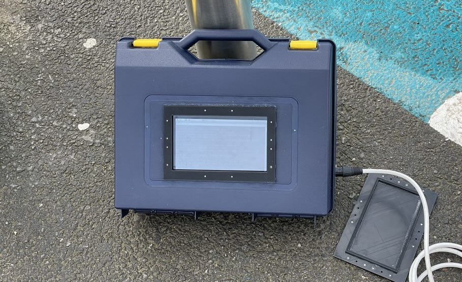
The primary objective of this research is to comprehensively understand the current implementation status of the Combined Charging System in real-world deployments. More specifically, we want to understand whether older charging station deployments are being updated to accommodate new features such as TLS and Plug-and-Charge, and if design flaws, such as default keys, leave the doors open for attackers. To achieve this, we built a data collecting device shown in Figure 2 that mimicked the behavior of a standard-compliant electric vehicle. The data collector was able to perform the basic signaling, matching, and portions of the higher level communications. This made it possible to interface with charging stations and collect data about multiple levels of the protocol stack.
4.1. Scope
Since the goal of our research is to understand how already deployed EV charging stations implement the standards and charging protocols in the real world when communication with real vehicles, we implemented only the exact features, functionality and behavior of a real car. We would like to emphasized that additional security analysis and penetration testing of the charging stations could be conducted, but was outside the scope of this paper. Furthermore, we do not want to risk damaging the chargers, including causing any software issue that requires a reboot.
In addition, we decided to not implement TLS in our EV simulator for three key reasons. First, it would be difficult to ensure that our implementation is standards compliant, and produces reliable results. Secondly, while charging station and vehicle manufacturers can easily contract with V2G PKI providers, and generate the required certificates for TLS, as researchers we do not have the same capabilities. We have no knowledge of existing root certificates and no access to a signed vehicle certificate, which is required for mutual TLS in ISO 15118-20. Finally, we are still able to measure support for TLS during the plaintext SDP handshake, thus we argue that not implementing TLS does not affect the conclusions of our study.
We publish our data as anonymized statistics, as we do not intend to praise or shame any existing implementation. We present results with immediate security implications, such as the support for new versions and security features, as well as any other aspects of the protocol we were able to collect, hoping that it can inspire and serve as a reference for future work.
4.2. Experimental Questions
Keeping in mind the motivation of our research, the description of the CCS protocol, and the scope of our data collection, we decided to answer the following questions about the existing implementations:
4.2.1. Transport Layer Security
We note that ISO 15118 includes support for TLS connections, and this feature is the basis of future versions of the protocol. In particular, during the SDP process the vehicle can request to use TLS or an unencrypted session, and the charger can offer a session according to its capabilities. We investigate how a charger responds to a TLS SDP request, seeing if it meets the request, ignores it, or offers a downgrade to unencrypted communications. We are able to collect this data even without implementing any of the TLS protocol.
4.2.2. Standard Support
At the beginning of the V2G communication phase, the vehicle provides a list of the standards it supports, as well as a major and minor version number. To our current knowledge, the options for this field are: urn:din:70121:2012:MsgDef version 2.0, urn:iso:15118:2:2010:MsgDef version 1.0, urn:iso:15118:2 :2013:MsgDef version 2.0, and urn:iso:15118:-20:DC version 1.0. If the charger supports one of the protocols offered by the vehicle, it selects it, and communications continue using only the features described in that version of the standard. The vehicle defines a priority for each option, and out of the protocols that the charger supports, the charger should select the one with the highest vehicle assigned priority. The charger should not have a preference between the protocols that it supports, and should respect the order given by the vehicle.
Unlike the SDP negotiation, the charger cannot respond with an option we do not provide it, it must instead report a failure in negotiation. By offering each protocol as the single option, we are thus able with certainty to determine which protocols the charger supports.
4.2.3. Encryption Keys
As mentioned, the SLAC process is also used to distribute the NMK, which is the basis of all security in the HPGP physical link. While existing research has already shown that sending these keys in plaintext allows them to be sniffed even by a wireless attacker (baker2019losing, ), we further wanted to determine if they are generated as secure ephemeral random numbers, are random but constant, or follow clearly intentional patterns.
Furthermore, HPGP networks have a Network ID (NID), which should be derived from the NMK, but failing to do so does not compromise the rest of the protocol. We thus calculated the expected NID from the NMK received, and compare it to the observed one, to determine compliance with this portion of the standard.
4.2.4. MAC Addresses
To gain an insight into the hardware choices, we collect the MAC addresses of the chargers, as well as the IPv6 address they assign themselves. We are interested in the Organizationally Unique Identifier (OUI) region of the MAC address, as it will likely reflect the manufacturer of the Ethernet chip, or the embedded computer. We are also interested to see whether the addresses are different between chargers, or if they are all provisioned with a completely identical firmware.
4.2.5. IP Addresses and Ports
During higher level communications, UDPv6 multicast is used for the SDP, and TCPv6 unicast is used for the V2G communications.
The IP address and port to connect to for the V2G session is provided to the EV by the charger in the SDP response, and we collected both.
We expect that the port offers insight into the internal implementation of the charger, and can help identify V2G implementations.
Specifically, each implementation can have a different fundamental strategy, we expect to see the following options:
Static Port: The charging station controller uses a static port.
Single Random Port: The charging station controller opens a single random server socket and uses it for all vehicles until the next reboot.
Random Port: The charging station controller opens a random (ephemeral) port for each new vehicle. This information could help distinguish between operating systems that allocate sequentially or randomly.
4.2.6. Attenuation
The basis of a successful and correct SLAC process is that all chargers are able to correctly measure the signal strength. Very large differences between chargers could mean that in neighboring installations a vehicle could get confused and select the wrong one. We collect the attenuation data reported by chargers, to determine whether the values seem reasonable, and of similar magnitude.
4.2.7. Similarity
We note that there are only a handful of companies that have designed and manufacture EV chargers, and there are also a handful of companies operating charging networks. However, these two groups of companies are largely separate, and network operators must purchase chargers from the manufacturers. It is expected that the firmware of the devices will be customized for each operator, both for aesthetic purposes, and to integrate their charging app and payment backend. We expect to see the same charger deployed by different networks, as well as the same network deploying a few different chargers. The differences between these allows us to investigate the extent of firmware customization.
Furthermore, within the same manufacturer and operator, we expect to find devices manufactured and installed years apart. Identifying differences between chargers that only differ in their age could indicate a lack of regular software updates.
4.3. Car Simulator
To answer our questions, we developed a car simulator that performs the CCS charging process until the standard negotiation phase of the V2G communication. We implemented the basic signaling, HPGP and SLAC, service discovery, and the first two messages of the V2G communication. We took inspiration from the work done in (pyPLC, ), however implemented our own customized hardware and software.
At the physical level, our device consists of a 3D-printed CCS Combo 2 socket, as it can be found on a vehicle. We added three pins, one for the Control Pilot (CP), one for the Proximity Pilot (PP) and one for Protective Earth (PE). We had no interest in accessing any power from the charger, and we did not add any pins to the power carrying part of the plug. As we do not reach the current delivery phase of the charging process, we do not expect any power to be present on the high voltage pins, but our plug ensures that they are safely sealed inside just in case.
We built a simple circuit board, that contains the electronics needed to perform basic signaling, additional details and schematic can be found in Appendix A. We used the MCP3004 analog-to-digital converter to measure the pulse-width modulation signal transmitted by the charger, and we used the appropriate load resistors and MOSFET switches to allow our vehicle simulator to alter the applied load, as required and defined in the standard. We deviated from a real vehicle in one way: to simplify experiments and facilitate data collection, our board is able to electrically simulate unplugging itself, instead of requiring a physical disconnection of the plug. This allows the data collection to be executed almost fully automated, as the EV simulator can re-connect itself multiple times and iterate through the different experiments.
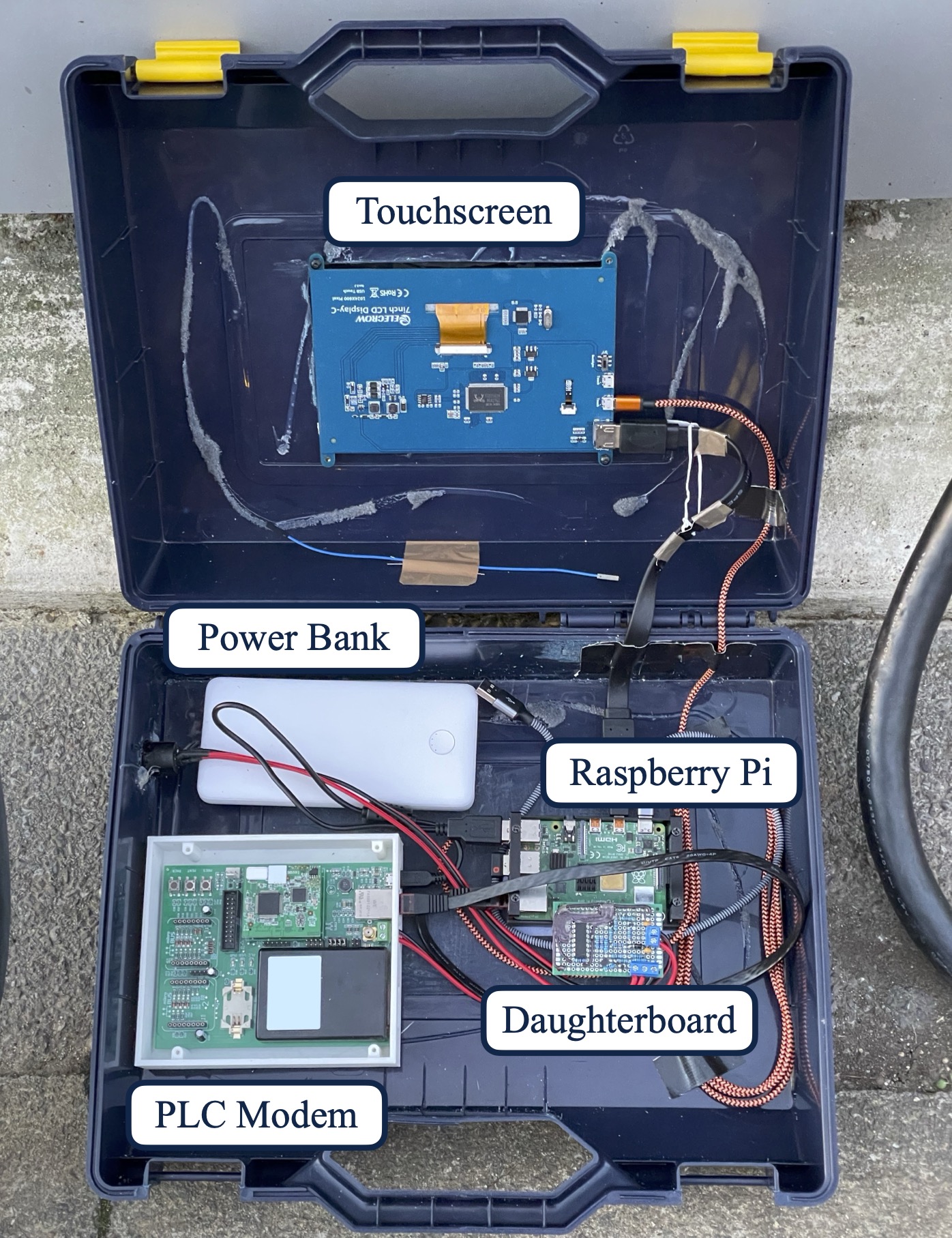
Our basic signaling board is built as a hat for a Raspberry Pi 4, which was used to run the data collection software. To provide HPGP capabilities, we connected a HomePlug Green PHY development board from Devolo to the Pi using Ethernet. We also added a touchscreen, and power the setup from a powerbank for convenience. The ensure portability of the simulator, we mounted everything into a transport case, and the full device can be seen in Figures 2 and 3. A wireless keyboard can be used in addition to the touch screen to efficiently interact with the command line.
To simulate the software aspects of the EV, as well as collect data, we created the following software stack. We ran Raspbian on the Raspberry Pi and used the Linux kernels implementation for the IPv6 and TCP/UDP stacks. We modified the slac/pev example from the open-plc-utils project by Qualcomm111https://github.com/qca/open-plc-utils, which contains a full implementation of the SLAC process from the vehicles side. We modified this C program to interface with the basic signaling daughter board via GPIO, and to also perform the SDP and V2G communications after the SLAC succeeds222Our source code will be made available after publication.. We wrote these layers on top of the Linux socket API. For the purpose of our evaluation, we extensively logged all valuable data that might help to answer our research questions. In addition, we put the Homeplug modem in Monitor mode using plcmon.py from (HomePlugPWN, ), and used tcpdump to collected sniffed Beacon frames and a full packet captures of every Ethernet packet sent over the HPGP network link.
We processed the log files from our script and the raw packet captures in a largely automated system, which emitted a distilled version of the data. We looked through the outputs manually to distinguish between human friendly patterns, and random values, as well as to spot any anomalies.
4.4. Experimental Methods
To answer our questions, for each new charger we conducted a standard set of experiments. We began with basic signaling by switching from the A1 to B1 state, and waiting for the charger to enter B2. We then performed SLAC, and logged the NMK, NID, MAC addresses and attenuation profile. Our first experiment was a TLS SDP request, and we logged the response packet containing the IP and port of the server, as well as its TLS support. We then did a No TLS SDP request, and used the obtained server address to perform 6 V2G protocol exchanges. First, we offered every known protocol as a choice, allowing the charger to select. We set higher priorities for the more advanced protocols, thus the choice of the charger should indicate the highest supported protocol. Then, we offered each of the four known protocols individually. To construct these test packets, we first created the XML in accordance with the standard (std_ISO_15118_2, ), and then used the V2G Decoder (V2Gdecoder, ) EXI implementation to convert them into compressed bytes. To eliminate potential errors due to our encoder, our final experiment was a real protocol request packet captured from a real vehicle, and we used it to sanity check the behavior of the charger against the generated packets.
For efficiency of data collection, we implemented an optimized data collection approach. This means that we re-used the IP and port given by the SDP process for all of the V2G messages. When we observed that our connection did not work, we attempted a new SDP process to refresh the server socket in the charger, and obtain the new port. When the SDP failed, we performed a full re-connection of the simulator at the Basic Signaling level, followed by a new SLAC exchange. In cases where the charger allowed multiple higher level connections without a full replugging and SLAC, this greatly improved our data collection speed.
At the end of the session we ensure that at minimum two SDP attempts are made without TLS to observe the port behavior, and that minimum two SLAC exchanges are made to observe the NMK behavior.
4.5. Charging Station Selection Strategy
Early on we observed that while charging station manufactures and network operators are largely separate companies, one network operator only uses a small number of different models, from one or two manufacturers. To ensure that our results are meaningful and indicative of the current deployment, we made an effort to visit as many network operators as possible. We tried to measure the same operator in multiple places, allowing us to see whether the same operator uses different charger models, and to differentiate device specific behavior from systematic. We identified urban areas with a dense EV charger deployment, allowing fast collection of many data points, however we found that each city was dominated by only a single network, with identical devices installed in a short amount of time. To increase the diversity in our dataset, we visited multiple small cities and installations along main roads.
5. Results
In total, we successfully investigated 105 CCS connectors, at 48 charging installations (defined as one or more chargers in close proximity). These spanned 17 different charging network operators, and 11 different manufacturers. We visited 4 major cities, and 6 additional smaller towns, throughout the United Kingdom.
During our experiments, we found some connectors to be in use by legitimate EVs, and did not disturb them. We also found some chargers to be broken, confirmed by both our measurements and by conversations with drivers trying to charge their vehicles. A common issue in our experience was a partially broken SLAC process, where the PLC modem can be detected due to its beacon frames, however it does not respond to SLAC. We are confident that this is not an issue with our setup, as we could often successfully measure a different plug on the same charging station. Furthermore, many chargers had issues with their payment terminals, which was rarely an issue for us, as most of the network operators did not require a payment before the protocol negotiation stage.
We first present our raw findings for each of the experimental questions we posed, followed by a more generic discussion about the state of the CCS deployment, the implications for security, and future outlooks. We present our results for each behavior trait by showing the number of devices in our dataset, as well as the number of manufacturers and networks exhibiting the given behavior. If a network or manufacturer exhibits multiple different behaviors, we count them in the ”Sometimes” category. Similarly, if we were unable to obtain a given data point, we omit that device. Later on in the discussion, we present some extrapolation from our data to wider trends, hoping to scale for any selection bias present in our data.
5.1. Similarity
As a general result, we found that within one manufacturer, behavior in all of the tested categories is largely identical. We noticed only a few small differences between different charging networks deploying from the same manufacturer. Thus in our findings, the (manufacturer, network) tuple is sufficient to describe the behavior of a given charger. We saw no instance of chargers behaving differently based on their age when deployed by the same network and manufacturer.
5.2. TLS Support
| Breakdown | No | Sometimes | Yes |
| Networks | 14 | 1 | 2 |
| Manufacturers | 8 | 2 | 1 |
| Devices | 84 | N/A | 16 |
| 2018 | 2 | N/A | 7 |
| 2019 | 3 | N/A | 6 |
| 2020 | 2 | N/A | 0 |
| 2021 | 27 | N/A | 0 |
| 2022 | 24 | N/A | 0 |
| 2023 | 15 | N/A | 0 |
| Unknown | 11 | N/A | 3 |
For the SDP responses, all chargers responded to a No TLS SDP request with a No TLS response, hence no charger attempted to upgrade our connection. It is likely that some older vehicles do not and will not support TLS, so any charger that does not support a No TLS session would be unusable to these customers. Furthermore, a vehicle does not only need to support TLS, it must have the correct root certificate used by the given charger installed. Chargers took three different approaches to handling TLS queries, they either ignored it, replied with No TLS (downgrade), or replied with TLS (support). The breakdown of these results is shown in Table 3.
We conclude that TLS support in currently deployed devices is generally rare, even though it is a mandatory requirement for the PKI based Plug and Charge system in 15118-2, and for all of -20. We also note from our results that the availability of TLS does not correlate with the age of the device, with many chargers built in 2023 still not supporting it. Instead, we observed that only three networks had TLS supporting devices, regardless of the age of the tested device. As they happened to do large deployments in 2018 and 19, we found the TLS supporting devices released at that time.
In addition, we conclude that ignoring a TLS SDP packet is generally rare, with only 4 out of 105 devices doing so. This behavior violates the standard, which requires chargers not supporting the feature to perform a downgrade. It may cause issues with newer EVs that request a TLS based session, and do not have a fallback to send a No TLS SDP request as well.
5.3. Standard Support
| Breakdown | DIN | 15118-2:10 | 15118-2:13 | 15118-20 |
|---|---|---|---|---|
| Networks | 17/0/0 | 3/2/12 | 9/2/6 | 0/0/17 |
| Manufacturers | 11/0/0 | 2/0/9 | 5/1/5 | 0/0/11 |
| Devices | 96/0 | 23/77 | 57/43 | 0/100 |
| 2018 | 9/0 | 0/9 | 3/6 | 0/9 |
| 2019 | 9/0 | 0/9 | 1/8 | 0/9 |
| 2020 | 2/0 | 0/2 | 0/2 | 0/2 |
| 2021 | 27/0 | 0/27 | 13/14 | 0/27 |
| 2022 | 24/0 | 14/10 | 22/2 | 0/24 |
| 2023 | 15/0 | 9/6 | 15/0 | 0/15 |
| Unknown | 10/0 | 0/10 | 3/7 | 0/10 |
| No TLS | 84/0 | 23/61 | 51/33 | 0/84 |
| Has TLS | 16/0 | 0/16 | 6/10 | 0/16 |
In the protocol analysis test, we offered all known protocol versions to the devices individually, and recorded their response. As per the standard, the charger should select the offered protocol if it is supported, or indicate that it is not. In reality, some chargers that do not support the protocol just closed the socket without sending a response. We further note an oddity in responses: some chargers sent the failure packet, and immediately terminated the TCP connection via a force close RST. We believe this to be a poor choice, as in most operating systems the receive buffer is immediately deleted when an RST packet is received (tcp_rst, ). This makes it impossible for the EV to actually receive the response packet before the socket is terminated.
Our results for the protocol test can be seen on Table 4. We conclude that DIN SPEC 70121 is supported by all chargers, with a fraction of chargers also supporting ISO 15118-2:2013. Finally, we saw some chargers that support -2:2010, but these chargers also all supported -2:2013.
We also observed that there were chargers which support TLS, however do not support ISO 15118-2:2013 in non TLS mode. However, DIN 70121 does not use TLS, so we find this response odd. As we do not initiate a TLS session, we cannot tell if the SDP response is an error, or the device only supports 15118-2 in TLS mode, and forces other vehicles to fall back on DIN.
We also gave tested devices a choice between all known protocols, and gave the highest priority to the newest protocol. Per the standard, the charger has to pick the highest priority that it supports, and we found this behavior consistent with the individual test results. Furthermore, to rule out any potential error with our EXI encoder, we used a packet captured from a real vehicle that offered DIN and ISO 15118-2:2013. We sent this packet, and found the behavior of all chargers to be consistent with the other experiments.
5.4. Encryption Keys
As per the standard (std_ISO_15118_3, )[V2G3-A09-92] we expect that a new, random NMK is used for each vehicle connecting. The NID should be derived from the NMK, based on PBKDF 1, as specified by (std_HPGP, ). To study this, we collected at least two SLAC processes, and thus two NMKs and NIDs from each charger investigated. We visually inspect the NMKs, to see if any pattern or similarity can be seen in them, and found that chargers fall into three categories. In the first category, the NMK appears to be randomly chosen, regenerated for each connection, and the NID is generated correctly. This behavior follows the standard, and is implemented by most devices. In a second category, we found one manufacturer across two networks which generates 4 random bytes, and use it to derive both the NMK and NID by padding them with a constant pattern. Finally, we found one manufacturer using a static, clearly human chosen value.
5.5. MAC Addresses
We collected the MAC addresses of the chargers, and analyzed their Organizationally Unique Identifier (OUI) to gain insights into the manufacturers of the PLC modems and embedded systems. We note that MAC addresses can always be overwritten by the software/firmware, so our results are merely indicative. In Table 5 we show the observed manufacturers.
We observer three different behaviors between devices. Some devices were set to a MAC address belonging to an EV charger specific manufacturer, some devices were set to a MAC corresponding to a large generic electronics supplier, and some had special addresses. Most special addresses had the locally administered bit set, meaning that the address does not need to be unique. We re-tested some of these chargers a few days apart, and found that they had changed addresses. For one charger, we also observed it using an address from an IANA region, used for special purpose addresses.
We also noticed that the manufacturer using the NXP Semiconductors OUI set the same, human friendly pattern for the remaining bytes of the address.
| OUI | Devices | Type |
|---|---|---|
| GloQuad | 1 | Charger |
| Huawei Technologies Co.,Ltd | 1 | Generic |
| I2SE GmbH | 16 | Generic |
| ICANN, IANA Department | 1 | Special |
| Kempower Oyj | 9 | Charger |
| Local, Non-Unique | 28 | Special |
| Microchip Technology Inc. | 29 | Generic |
| NXP Semiconductors | 5 | Generic |
| Tritium Pty Ltd | 14 | Charger |
| Wall Box Chargers, S.L. | 1 | Charger |
5.6. IP Addresses
We collected the IPv6 address given by the charger during the SDP process. As per the standard (std_ISO_15118_2, )[V2G2-051], link local IPv6 addresses should be used, and all devices should generate it from their MAC address following RFC 4291. We validate that most devices follow this method, with only one manufacturer using seemingly random addresses in the link-local space. Because of the SDP process, no specification compliant vehicle should require the IP address to be generated in this way, so we do not expect this to be an issue.
5.7. Server Ports
Based on our observations, we were able to classify devices into the expected categories based on server port selection. We found devices with ephemeral random, ephemeral incrementing, and constant ports. By comparing the constants between identical charger models, we can further divide constant ports which appear to be hard coded, and ports which appear to be chosen randomly at system startup. We do not believe there is any real security implication behind ports being predictable, but generally believe that a random ephemeral port is the safest choice in any case.
5.8. Attenuation
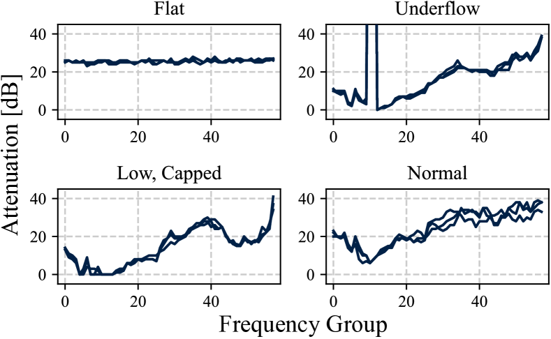
We observed that all devices returned different attenuation profiles on subsequent measurements, indicating that they do not have a hard coded value, and instead perform some measurement. However, we observed three anomalies, and we plot the corresponding signals in Figure 4.
First, we observed the shape of the attenuation profile. During the SLAC process, we receive not only a single number, but a profile of the attenuation as a function of frequency. Most chargers respond with a similar shape, showing higher attenuation at low frequencies due to the high-pass filter separating the PLC signal from the basic signaling PWM signal, as well as higher attenuation at high frequencies due to various losses. The difference between min and max attenuation can easily be . However, one charging manufacturer responds with a very flat profile, within of the average. Given that the measurements still contain noise, which varies for each subsequent run, we argue that these are also based on real measurements, but they are likely calculated after some form of channel equalization.
Secondly, different charger models have different attenuation levels. This could be an issue when two such chargers are installed in close proximity, since a vehicle might accidentally connect to the wirelessly coupled, low attenuation charger as opposed to the wired high attenuation one. Discrepancies may be due to variations in PLC chips, internal attenuation or charging cables. In our findings, we see differences of about to be common, but we expect attenuation due to wireless coupling to be higher in all but the worst case.
Finally, we occasionally observed an underflow in the data. As per the specification, the attenuation for each frequency is an unsigned byte, however one charger manufacturer would regularly underflow, and send very high () attenuation. In a reasonable vehicle, which averages all the unsigned bytes to determine a singular attenuation, this may cause issues. Having a few of these very high values in the average can easily cause the vehicle to calculate a higher average attenuation for the charger it is directly connected to, then for a charger that it is not connected to, and which thus does not underflow.
We believe that charging station manufacturers should work to calibrate their signal strength measurements to provide consistent, and real results. The calibration should be done end-to-end, to compensate for the cable, analog front end and PLC chip. Furthermore, steps should be taken to avoid underflows when reporting the result, as we saw some manufacturers correctly cap their measurements at 0. We note that ISO 15118-5 includes conformance tests for the physical layer, however we are unable to find any tests that require measurements to be accurate and calibrated against a reference signal, as the standard is focusing on the protocol state machine.
6. Discussion
While we did not visit and analyze all deployed charging stations, our data collection process yielded enough data points to draw meaningful conclusions. In order to extrapolate our findings, we extracted information about charging stations using data from one of the largest EV charger databases, Zap-Map. We were able to obtain a reasonably accurate counts for the number of CCS plugs deployed by each network, and in some cases we could also determine the manufacturer. Using these estimates for the scale of each network, we can extrapolate, and we discuss this below.
6.1. Protocol Support
The most important question in our opinion is the support for newer standards. In order to drive the industry forward, it is essential that chargers and vehicles both adopt new technologies. This benefits the end users directly with the introduction of new features, as well as via increased security. Even though TLS for EVs was introduced by ISO 15118 in 2014, 10 years later the support for it remains limited in the real world. In our experiments we found only 3 out of 11 networks which support TLS, and we note that while one of them is a quite large network, the other two are smaller. While in our data we saw 16% of chargers using TLS, by using estimated sizes for the networks we approximate the real value to be about of the country.
We speculate that this is because, ignoring the security benefits, there is currently little incentive for manufacturers to implement it, while there is a lot of added complexity. We now consider the implementation of TLS, ISO 15118-2 and -20 from the standpoint of a manufacturer. As long as EV charging attacks remain purely academic, with no significant real world exploitation, the security benefits of the new protocols is negligible to manufacturers and network operators. Instead, the benefits are via an enhanced user experience and new features.
ISO 15118-2 introduces a PKI based Plug and Charge (PnC) system, which allows users to simply plug in their vehicle, and be automatically billed for the used electricity. Firstly, adding TLS support to a charger means that each charger must have a certificate, with a chain leading back to a V2G root certificate trusted by the vehicle. While there are many providers for TLS certificates for the web, including free options, the case is not the same for EV charging. We have only found a handful of major providers offering commercial V2G certificates (v2groot_charin, ; v2groot_hubject, ; v2groot_irdeto, ). After obtaining the certificates, implementing the PnC feature requires connection to the Open Charge Point Protocol (OCPP) backend to transfer information between payment operators and charging networks. In our view, it is reasonable for a manufacturer to not implement this feature until the consumers demand it, and start preferring alternative charging operators.
In addition, the new features of ISO 15118-20 offer little value for public charging network operators. Public DC fast chargers are often used during long trips, where fast recharging is desired. Thus, the reversible power transfer, and scheduled charging features offer little value. For overnight charging, simple AC charging can be used which is often much cheaper and better for the battery.
This is different in a private context, e.g. delivery fleets and buses charging at their own hubs. In this case, PnC can be implemented via a private root certificate exclusive to the fleet and their chargers, and the scheduled or bidirectional charging may be useful to lower costs or even act as an additional revenue stream when the vehicles are parking overnight at the depot. As these chargers are not open to the public, we were unable to examine their current deployment. We thus believe that the current state of public EV charging deployment is reasonable given the market conditions.
6.2. Security Concerns
Our key finding with regards to security is the lack of support for new protocols and TLS. We now briefly analyze our results in the context of research from the security community.
6.2.1. Physical Layer Attacks
The first class are physical layer attacks, which target the basic or higher level signaling. The Brokenwire (kohler2023brokenwire, ) attack performs a very power efficient jamming on the HPGP physical link, achieving wireless attacks against the wired channel. As this layer is below TLS, and because even ISO 15118-20 uses the same physical layer as previous versions, no currently standard revision or TLS upgrade can prevent this attack, and it thus remains an issue with all foreseeable future CCS deployments. Outside of the EV context, in (dayanikli2022physical, ), the authors demonstrated wireless attacks against PWM signals. The same type of signal is used as part of basic signaling, which may thus be vulnerable. As the newer standard revisions do not modify the basic signaling, this also remains vulnerable.
6.2.2. Protocol Attacks
Protocol attacks target portions of the V2G protocol, and have been the focus of intensive research. The EVExchange (conti2022evexchange, ) attack has been proposed to allow an attacker to charge their vehicle while the victim pays. The authors claim that their attack can operate fully without modifying packets, leaving even TLS connections vulnerable. We argue that TLS and ISO 15118-20 could prevent the attack, since constant current delivery packet heartbeats are exchanged that cannot be modified without access to the private key.
Two research projects (baker2019losing, ) and (dudek2019v2g, ) have demonstrated the extraction of the NMK from the SLAC process wirelessly or via connecting to the cable respectively. Dudek et al. (dudek2019v2g, ) further demonstrate that they can join the network and inject packets into the network. A TLS based session secures against passive eavesdroppers and should even remain secure against most forms of active MITM attacker, as long as they do not possess a trusted certificate belonging to a charger. Thus, these attacks could easily be prevented by upgrading.
6.2.3. Countermeasures
The community has been actively proposing modifications to the ISO 15118 protocols to increase security and privacy. The TrustEV (fuchs2020trust, ) system proposes using a TPM to store credentials for ISO 15118. From our observations we concluded that so far even basic security features, that only require a software update (i.e. TLS and ISO 15118-2) have not seen widespread adoption. We are thus skeptical about the future adoption of a system that requires additional hardware in each vehicle and charger. Nonetheless, we believe that such hardware changes should be incorporated into future devices, allowing them to be rolled out during the natural replacement cycle of devices.
6.3. Related Work
To the best of our knowledge, this work is the first measurement study on the protocols being deployed as part of CCS. However, there exists prior work examining the deployment of charging networks. In (chen2020review, ), the authors present a review of charging deployment in the UK, with a focus on geographic distribution, and power usage. In addition, multiple studies offer a comprehensive overview of EV charging, discussing non-CCS technologies, capabilities of EVs, legislation and market trends (mastoi2022analysis, ; amel2024charging, ).
Similar to our EV simulator, the pyPLC project (pyPLC, ) implements the basic communication and functionalities of CCS. In contrast to our work, its primary goal is to allow the power transfer from chargers to various devices and even to charge a customized electric vehicle. In addition, software implementations exist for the EV and charger side of the entire V2G protocol (rise_v2g, ; switch_iso15118, ), and simulators have also been developed with a research focus (madhusudhanan2022development, ).
7. Ethical Consideration
We analyze the ethics of our experiments from two angles. First, from a data privacy perspective, we foresaw no way in which data associated with another customers charging session could be stored by the charger and leaked to us. We never collected data on charging session performed by members of the public, only connecting our own vehicle simulator. With regards to the data collected, we believe that none of the data collected is sensitive in nature.
Secondly, from a public safety perspective, we believe that allowing the research community and the public to know the current state of security implemented in EV charging systems will better inform future research directions and policy making, and may help put pressure on charger manufactures to update to newer versions of the standard, thus mitigating known issues. We do not publish our data in a way that allows connecting manufactures and network operators to their observed behavior, thus any potential attacker would still need to make their own research to identify appropriate targets.
During our research we do not perform any offensive security testing, but simply measure support for existing standards. As such, the lack of new, more secure standards is not a newly discovered vulnerability, but a conscious choice by manufacturers. For this reason we did not perform any disclosure to manufacturers.
8. Limitations
We acknowledge that our survey provides a snapshot of the current state of EV charging infrastructure deployment in the United Kingdom. However, given that the country is one of the leaders in terms of EV charging infrastructure deployment, we argue that our findings can be extrapolated to other countries. This assertion is supported by the widespread presence of many network operators in different countries and their use of the same charging station manufacturers. In addition, we are aware that our testing included a limited number of charging stations. Nevertheless, our study rigorously tested multiple devices for the largest network operators and manufacturers in our region. While it was our intention to capture a larger sample size, several constraints hindered our efforts. For example, some charging stations were in use or out of service due to technical issues. We leave the room open for future work, by increasing the sample size. In addition, future work could implement TLS, and collect information about ISO 15118-2, such as the cipher suits or certificate chains. Furthermore, researchers able to obtain a vehicle certificate could also probe deeper into 15118-20.
9. Conclusion
In this paper, we showed that a majority of the current charging infrastructure (84% of tested devices) does not implement TLS, and thus modern parts of the ISO 15118 standard. We explained why we believe outdated implementations are so common, and analyzed the situation in the context of existing security work. We identified known vulnerabilities that could directly be prevented by deploying TLS and modern protocols. In addition, we presented results about other implementation details of CCS, and identified anomalous behavior in the NMK selection and SLAC process of some devices, and call for additional standardization.
Availability
Details and source code of our data collection system, as well as more granular data will be made available on publication.
Acknowledgments
We would like to thank armasuisse Science + Technology for their support. Marcell was funded by the Engineering and Physical Sciences Research Council (EPSRC) and Sebastian was supported by the Royal Academy of Engineering and the Office of the Chief Science Adviser for National Security under the UK Intelligence Community Postdoctoral Research Fellowships programme.
References
- (1) J. Antoun, M. E. Kabir, B. Moussa, R. Atallah, and C. Assi, “A detailed security assessment of the ev charging ecosystem,” IEEE Network, vol. 34, no. 3, pp. 200–207, 2020.
- (2) R. Baker and I. Martinovic, “Losing the car keys: Wireless PHY-Layer insecurity in EV charging,” in 28th USENIX Security Symposium (USENIX Security 19). Santa Clara, CA: USENIX Association, Aug. 2019, pp. 407–424. [Online]. Available: https://www.usenix.org/conference/usenixsecurity19/presentation/baker
- (3) K. Bao, M. Wagner, H. Valev, and H. Schmeck, “A threat analysis of the vehicle-to-grid charging protocol iso 15118,” Computer Science - Research and Development, 09 2017.
- (4) A. Benmouna, L. Borderiou, and M. Becherif, “Charging stations for large-scale deployment of electric vehicles,” Batteries, vol. 10, no. 1, 2024. [Online]. Available: https://www.mdpi.com/2313-0105/10/1/33
- (5) CharIN, “Ccs specification.” [Online]. Available: https://www.charin.global/technology/ccs-specification/
- (6) ——, “Public key infrastructure (pki).” [Online]. Available: https://www.charin.global/pki/
- (7) T. Chen, X.-P. Zhang, J. Wang, J. Li, C. Wu, M. Hu, and H. Bian, “A review on electric vehicle charging infrastructure development in the uk,” Journal of Modern Power Systems and Clean Energy, vol. 8, no. 2, pp. 193–205, 2020.
- (8) M. Conti, D. Donadel, R. Poovendran, and F. Turrin, “Evexchange: A relay attack on electric vehicle charging system,” in Computer Security – ESORICS 2022, V. Atluri, R. Di Pietro, C. D. Jensen, and W. Meng, Eds. Cham: Springer International Publishing, 2022, pp. 488–508.
- (9) G. Y. Dayanıklı, S. Sinha, D. Muniraj, R. M. Gerdes, M. Farhood, and M. Mina, “Physical-Layer attacks against pulse width Modulation-Controlled actuators,” in 31st USENIX Security Symposium (USENIX Security 22). Boston, MA: USENIX Association, Aug. 2022, pp. 953–970. [Online]. Available: https://www.usenix.org/conference/usenixsecurity22/presentation/dayanikli
- (10) “DIN SPEC 70121: Electromobility - digital communication between a d.c. ev charging station and an electric vehicle for control of d.c. charging in the combined charging system,” Tech. Rep., 2014.
- (11) S. Dudek, “Homeplugpwn,” https://github.com/FlUxIuS/HomePlugPWN, 2021.
- (12) S. Dudek and contributors, “V2gdecoder,” https://github.com/FlUxIuS/V2Gdecoder, 2022.
- (13) S. Dudek, J.-C. Delaunay, and V. Fargues, “V2g injector: Whispering to cars and charging units through the power-line,” in Proceedings of the SSTIC (Symposium sur la sécurité des technologies de l’information et des communications), Rennes, France, 2019.
- (14) European Commission, “Directive 2014/94/eu of the european parliament and of the council,” 10 2014. [Online]. Available: https://eur-lex.europa.eu/legal-content/EN/TXT/HTML/?uri=CELEX:32014L0094&from=en
- (15) ——, “Alternative Fuels Observatory,” 2023, Accessed: February 7, 2024. [Online]. Available: https://alternative-fuels-observatory.ec.europa.eu/transport-mode/road/eu27-uk-norway-iceland-switzerland-turkey-liechtenstein
- (16) Federal Highway Administration, “88 FR 12724, national electric vehicle infrastructure standards and requirements,” 2023. [Online]. Available: https://www.federalregister.gov/d/2023-03500
- (17) S. Fries and R. Falk, “Electric vehicle charging infrastructure – security considerations and approaches,” 06 2012.
- (18) A. Fuchs, D. Kern, C. Krauß, and M. Zhdanova, “Trustev: trustworthy electric vehicle charging and billing,” in Proceedings of the 35th Annual ACM Symposium on Applied Computing, ser. SAC ’20. New York, NY, USA: Association for Computing Machinery, 2020, p. 1706–1715. [Online]. Available: https://doi.org/10.1145/3341105.3373879
- (19) U. Hennig, J. Huebner, A. J. Kramer, and J. Pouw, “pyplc,” https://github.com/uhi22/pyPLC, 2024.
- (20) HomePlug Powerline Alliance, “HomePlug Green PHY Specification, Release Version 1.1.1,” Standard, 2013.
- (21) Hubject, “Seamless and secure charging.” [Online]. Available: https://www.hubject.com/products/plug-and-charge
- (22) “Iec 61851-1. electric vehicle conductive charging system. part 1. general requirements,” Tech. Rep., 2017.
- (23) “Iec 62196-2. plugs, socket-outlets, vehicle connectors and vehicle inlets - conductive charging of electric vehicles - part 2: Dimensional compatibility requirements for ac pin and contact-tube accessories,” Tech. Rep., 2022.
- (24) “Iec 62196-3. plugs, socket-outlets, vehicle connectors and vehicle inlets - conductive charging of electric vehicles - part 3: Dimensional compatibility requirements for dc and ac/dc pin and contact-tube vehicle couplers,” Tech. Rep., 2022.
- (25) Irdeto, “Irdeto launches north american v2g trusted root ca to accelerate plug & charge adoption.” [Online]. Available: https://irdeto.com/news/irdeto-launches-north-american-v2g-trusted-root-ca-to-accelerate-plug-charge-adoption/
- (26) “Iso 15118-2. vehicle to grid communication interface. part 2: Network and application protocol requirements,” Tech. Rep., 2014.
- (27) “Iso 15118-3. vehicle to grid communication interface. part 3: Physical and data link layer requirements,” Tech. Rep., 2015.
- (28) S. Köhler, R. Baker, M. Strohmeier, and I. Martinovic, “Brokenwire : Wireless disruption of ccs electric vehicle charging,” in NDSS Symposium, 2023.
- (29) O. Langlois, “TCP RST flag subtleties.” [Online]. Available: https://blog.olivierlanglois.net/index.php/2010/02/06/tcp_rst_flag_subtleties
- (30) M. S. Mastoi, S. Zhuang, H. M. Munir, M. Haris, M. Hassan, M. Usman, S. S. H. Bukhari, and J.-S. Ro, “An in-depth analysis of electric vehicle charging station infrastructure, policy implications, and future trends,” Energy Reports, vol. 8, pp. 11 504–11 529, 2022. [Online]. Available: https://www.sciencedirect.com/science/article/pii/S2352484722017346
- (31) M. Mültin, “What is iso 15118?” Switch EV. [Online]. Available: https://www.switch-ev.com/blog/what-is-iso-15118
- (32) M. S and P. Sivraj, “Development of communication simulator for electric vehicle charging following iso 15118,” in 2022 IEEE North Karnataka Subsection Flagship International Conference (NKCon), 2022, pp. 1–6.
- (33) “Sae j1772: Electric vehicle and plug in hybrid electric vehicle conductive charge coupler,” Tech. Rep., 1996.
- (34) SwitchEV, “iso15118,” https://github.com/SwitchEV/iso15118.
- (35) ——, “RISE-V2G,” https://github.com/SwitchEV/RISE-V2G.
Appendix A Basic Signaling Hardware Interface
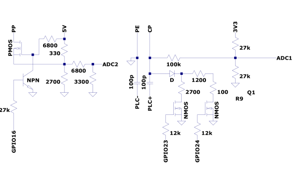
To implement basic signaling, we created a daughterboard that implements the loading and measurement of the Control Pilot (CP), as well as the generation and measurement of the Proximity Pilot (PP) signals. Furthermore, it separates the HPGP signal from the basic signaling PWM signal.
We implemented our board following the schematic provided in the standard, however we deviated in one key way, by adding the ability for our board to simulate a fully unplugged vehicle. To achieve this, we made two modifications: In a normal vehicle, the resistor triggering the B state on the control pilot is hard wired, while the resistor changing the B state into a C state is connected via a relay or solid state switch, and only activated when needed. To simulate a vehicle that is not connected, we also add an identical MOSFET switch to the B state resistor, allowing us to leave the charger in the A state. The voltage measurement resistive divider for the ADC is still connected, however its resistance is high enough to have only a negligible impact, and did not disturb any of the chargers we tested. Secondly, in a normal EV, the vehicle is responsible for generating the PP signal. This signal is intended to be generated and measured by the vehicle, and is used to detect if the cable is about to be unplugged. We are not aware of a reason for the charger to actually measure the PP signal, however we implement its generation just in case. To simulate unplugging the vehicle for the PP signal, we use a p-Channel MOSFET based high-side switching circuit, and a single transistor level shifter. This allows the generated PP signal to be disconnected from the charging cable.
We show the schematic in Figure 5, and note that the restive dividers for the ADC have been optimized for an ADC operating at .