Resource Management in RIS-Assisted Rate Splitting Multiple Access for Next Generation (xG) Wireless Communications: Models, State-of-the-Art, and Future Directions
Abstract
Next generation wireless networks require more stringent performance levels. New technologies such as Reconfigurable intelligent surfaces (RISs) and rate-splitting multiple access (RSMA) are candidates for meeting some of the performance requirements, including higher user rates at reduced costs. RSMA provides a new way of mixing the messages of multiple users, and the RIS provides a controllable wireless environment. This paper provides a comprehensive survey on the various aspects of the synergy between reconfigurable intelligent surfaces (RISs) and rate splitting multiple access (RSMA) for next-generation (xG) wireless communications systems. In particular, the paper studies more than 60 articles considering over 20 different system models where the RIS-aided RSMA system shows performance advantage (in terms of sum-rate or outage probability) over traditional RSMA models. These models include reflective RIS, simultaneously transmitting and reflecting surfaces (STAR-RIS), as well as transmissive surfaces. The state-of-the-art resource management methods for RIS-assisted RSMA communications employ traditional optimization techniques and/or machine learning techniques. We outline major research challenges and multiple future research directions.
Index Terms:
Reconfigurable intelligent surfaces (RIS), Rate splitting multiple access (RSMA), rate splitting, simultaneously transmitting and reflecting surfaces, transmissive RISI Introduction
Three Pillars formed the target of development in Fifth Generation (5G): Enhanced Mobile Broadband (eMBB), Ultra-Reliable Low-Latency Communication (URLLC), and Massive Machine-Type Communication (mMTC). The first pillar targets faster data rates to enable high resolution video streaming and augmented reality, with an average of 50 Mbps and a peak of 10 Gbps. The second pillar is for applications like autonomous driving and it targets latency on the order of a millisecond. The third pillar specifies a support for a million low-power devices per square kilometre. Newer generations, such as Sixth Generation (6G), aspire to reach higher requirements that necessitate the development of newer technologies that not only satisfy the connectivity and rate requirements, but also achieve better spectral and energy efficiencies. These include new multiple access techniques such as Rate Splitting Multiple Access (RSMA), in addition to Reconfigurable Intelligent Surface (RIS) which enables unprecedented level of control on the channel. These technologies are at the intersection of three foundations described in [69], namely: Communications foundations, Large intelligent surfaces foundations, and optimizations foundations.
Although orthogonal transmission techniques like Orthogonal Frequency-Division Multiple Access (OFDMA) are still prevalent, RSMA is a promising non-orthogonal transmission technique, which can lead the proliferation of Next-Generation Multiple Access (NGMA). In addition to the use of RISs, newer multiple access techniques are currently being considered for the Beyond 5G (B5G) and the upcoming 6G. Exploring the effect of the coexistence of these two technologies is an important discovery endeavour. In the following, we review the basics of RSMA and RIS.
I-A Rate Splitting Multiple Access
It was suggested that the mere classification of multiple access systems into orthogonal and non-orthogonal schemes is incomplete [81]. Instead, one should think about how the interference among multiple users is managed, and RSMA can provide a general framework to answer that question. RSMA has many variations [73], all are based on the idea of Rate-Splitting (RS) which splits the message at the transmitter into one or more pieces, and the splitting ratio must be known at the receiver [85]. More details on RS schemes can be found in [73, 81].
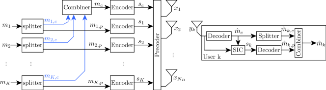
In the Downlink (DL) Space-Division Multiple Access (SDMA), or Multi-User (MU)-Linear Precoding (LP), the Base Station (BS) will send a data vector where is intended to the th user, and is only decoded by the th user while treating other interfering messages as noise. If Non-Orthogonal Multiple Access (NOMA) is used, each user decodes messages then subtracts them using Successive Interference Cancellation (SIC) to access its private message. In other words, the first user treats all interfering messages as noise, and decodes its message, then the second user decodes the message of the first user first, then applies SIC to cancel the interference of the that message, then decodes its message while treating the remaining messages as noise. Fig. 1 shows a conceptual view of the two systems just described (SDMA and NOMA) in addition to One-layer (1L)-RS described in the next paragraph. Fig. 2 shows the same for a four-user system.
1L-RS is a simple RS scheme where a single SIC layer is required at each receiver. In the DL, the message of each user is split into two (usually not equal) parts, the first part of each user is joined to form the common part , and the other part remains private to each user after decoding the common part . Hence, the BS sends the data vector , and the th user decodes first then decodes its private message . It is assumed that the codebook of the common stream is shared by all users, and that . Note that in the example of Fig. 1, each user has splits its message into two parts, one of them is within the common message that is decoded first by both receivers, that is in Fig. 1. In other words, the full message intended to user 1 will be composed of the portion in the common part in addition to the private part. This implies that if a user is unable to decode either the common or the private part, then that user will be in outage. Outage performance is discussed in Section III-D. NOMA is a special case of 1L-RS where there is no private message to the first user, and the message of the first user is the common message. That is, by setting , and . In case of no Quality-of-Service (QoS) constraints per users, e.g. no minimum rate requirements, then only one user has to split its rate [75]. Splitting the messages of multiple users was found useful in the cases of QoS constraints, such as rate requirements, max-min fairness and Weighted Sum-Rate (WSR) [75, 76, 86]. Note that the common rate is limited by the rate supported by the user with the least-favourable condition. One possible way to mitigate this limitation is the cooperative-RS which was proposed in [87] where the user with the better channel volunteers to deliver the common message to the other user having a weaker channel. The RIS-assisted cooperative-RSMA system has been shown to lower the energy consumption of the system [48]. A different view of the 1L-RS system is presented in Fig. 3 where a BS serves -users through antennas. Only a single receiver is shown since all receivers follow the same logic. In the notation of Fig. 1, and .
Another way of RS is called multicommon RS, where each user splits its message into two parts, just like 1L-RS, but the common messages of users are not combined into a single common message. Instead, each user gets a common and a private message that are encoded separately from the messages of other users. In other words, there are messages for users. The messages can then be transmitted from the same or different BSs. Different BSs are used in [4, 14]. A third way is the dual-polarized RS, which is similar to 1L-RS but uses different polarizations to send the common and the private parts. It is assumed that the receivers also use polarized antennas. This idea was proposed in [88], and is used by [38] in the RIS-assisted RSMA system.
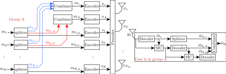
Two-layer (2L)-Hierarchal RS (HRS) is a more general RS scheme compared to 1L-RS. 2L-HRS boils down to 1L-RS when users are not grouped. In 2L-HRS, the message to each user is split into three parts: 1) a universal common part, 2) a group common part, and 3) a private part. These can be reworded as: 1) an inter-group part, 2) an intra-group part, and 3) a private part. Consequently, each user is required to perform SIC twice: Once for the universal common part, and once for the group common part. After that, the user gets to decode its private part. Fig. 2 shows an example with 4 users. Users 1 and 2 are in the same group while users 3 and 4 are in a different group. Each user compiles its message once it successfully decodes all three parts of its message. For instance, the message of user 1 is . It is assumed that . Another view for 2L-HRS is shown in Fig. 4 for -user multiple-input single-output (MISO) system. Users can be grouped to perform an extra SIC within the group. The common message is still made up of portions of the messages of all users. Similarly, the common message of the group is composed of portions of messages intended for users in the group. In terms of the notation of Fig. 2, , , for all in group A.


I-B Reconfigurable Intelligent Surface (RIS)
The RIS is an array of discrete elements that can be controlled over time. A metamaterial is a candidate material for manufacturing RIS elements. The term “meta” refers to the unusual properties of these materials, for instance, a negative or anisotropic refractive index [89]. Metamaterials are a periodic structure of metallic or dielectric units called meta-atoms, which resonate to the incident Electromagnetic (EM) wave [89]. If these metamaterials are layered in a planar structure, then they are referred to as a metasurface [89]. Manufacturing metasurfaces can be achieved through lithography or nanoprinting [89]. Simpler methods can be used if the wavelength is not too small. For instance, metasurfaces for light waves are typically manufactured using lithography techniques. Another example is the possibility to use metal patches for unit cells in the microwave frequencies [90]. The spacings between the meta-atoms are usually less than half wavelength [89]. Element dimensions are usually less than the wavelength of operation, e.g. [91]. The RIS can be passive or active. Passive surfaces do not amplify the incident signal, and the reflected signal can at best remain at the power of the incident signal. On the other hand, active surfaces can introduce gain in the reflected signal without using an Radio Frequency (RF) chain or signal processing. For example, the passive surface can be modelled as a passive filter, where each element can introduce a delay, attenuation, or a polarization change [91]. In addition, it can be classified in other ways like opaque vs. transparent (to the light wavelengths), or based on the connectivity modelling [84]. The RIS can be tuned to support communications, localization, power transfer, sensing, and physical layer security [92, 93]. This article focuses on the papers [1, 2, 3, 4, 5, 6, 7, 8, 9, 10, 11, 12, 13, 14, 15, 16, 17, 18, 19, 20, 21, 22, 23, 24, 25, 26, 27, 28, 29, 30, 31, 32, 33, 34, 35, 36, 37, 38, 39, 40, 41, 42, 43, 44, 45, 46, 47, 48, 49, 50, 51, 52, 53, 54, 55, 56, 57, 58, 59, 60, 61, 62, 63, 64, 65, 66, 67, 68], and the some of the assumptions they consider for the RIS are listed in Table III. The next paragraphs briefly introduce the reflective, transmissive, and Simultaneously Transmitting and Reflecting (STAR)surfaces.
I-B1 Reflective Surface
The reflecting surface is sometimes referred to as the Intelligent Reflecting Surface (IRS). Fig. 5 presents a sample unit cell of a metasurface. The figure is adapted from [90] but with a circular shape to illustrate that the unit cells need not be rectangular. Consequently the detailed dimensions of the unit cells in [90] are omitted. Details of the RIS are beyond the scope of this paper, but three modelling techniques will be highlighted. An RIS with elements can be modelled by an -port reconfigurable impedance network represented by a complex-valued scattering matrix that relates the incident and reflected waves at the surface. When the impedance network is single-connected, is a diagonal matrix, and there is a single impedance to tune for each element, or a total of elements per surface. This model is quite common in the literature. Another model for the RIS is the fully-connected model, which assumes that all the elements in the RIS are interconnected by an impedance [84]. For example, this model is adopted in [7]. In this model, each RIS element is connected to all other elements, hence the matrix is no longer sparse, and a total of scattering parameters need to be tuned (because each element still has one impedance connected to the ground). A third model is the group connected model [84], used by [36]. Admittedly, the number of parameters to tune in the fully-connected model just-described can be very complicated, thus, a group-connected model limits connectivity between elements to a few neighbouring elements, and the resulting scattering matrix is block-diagonal.
I-B2 Transmissive Surface
A quick analogy to describe the transmissive surface is to think of metalenses. A metalens is a thin metasurface structure that can be designed to manipulate light waves similar to traditional glass-based or plastic-based lenses. In that sense, the light passes through the surface with its amplitude, phase, polarization, or all of them altered. Similarly, a transmissive surface can modulate an EM wave as it passes through it. Compared to the reflective surface, however, the transmissive surface may be more difficult to manufacture if reconfigurability is desired. For instance, the back plane of the reflective surface can carry internal components to support the reconfigurability of the surface, while the transmissive surface has to maintain the bulk of both surfaces clear for the passage of the EM wave. Design of transmissive surfaces can follow techniques such as those described in [94, 95].
I-B3 Simultaneously Transmitting and Reflecting Surface
Simultaneously Transmitting and Reflecting (STAR)-RIS is a surface that can transmit and reflect (simultaneously or non-simultaneously) ‘portions’ of the incident signal. These ‘portions’ are determined according to three common protocols:
- 1.
- 2.
-
3.
Time Switching (TS) flips all elements from transmit mode to reflect mode at orthogonal time intervals. This mode requires synchronization and is not common.
Note that these signal splittings should not be confused with the signal splittings done by the RSMA protocol at the transmitter. Note also that ‘transmission’ in the context of Simultaneously Transmitting and Reflecting (STAR)-RIS is the mere passage of a portion of the incident signal to other half plane behind the surface, and does not imply signal generation at the surface. Thus, the STAR-RIS provides a full 3600 coverage in the Smart Radio Environment (SRE), i.e. it provides coverage to the two half planes before and behind the surface, and that is different from the Reflecting-only (RO)-RIS which only covers the half plane before the surface, or 1800. STAR-RIS is sometimes called intelligent omni-surface [96, 97] but may have a single tuning parameter for both transmission and reflection [98]. Controlling the transmission and reflection coefficients of the STAR-RIS independently require a semi-passive or active surface. Arbitrary independent assignment of the coefficients for the passive surface may be impractical [99].
I-C Synergy Between RSMA and RIS
Mutual gains have been reported for the RIS-assisted RSMA systems. The gains can be in terms of reduced complexity (e.g. 1L-RS is less complex compared to NOMA for three or more users), more energy/spectrum efficiency or more WSR, etc. In addition, some weaknesses of one technology can be reduced by leveraging the other one. Many benefits of combining RIS with RSMA were explored in [13] along with a brief on both technologies. For example, the role of the RIS as a passive (low cost) assistant in communications poses difficulty in Channel State Information (CSI) acquisition, which can be mitigated by the robustness of RSMA to imperfect CSI.
The idea of RS originated decades ago [70, 71, 72]. Since RS is good at handling interference in Single-input single-output (SISO) channels, further investigations into MISO channels led to the development of RSMA, which can be thought of as a generalization of both SDMA and NOMA [73, 74, 75, 76]. NOMA achieves capacity for SISO-broadcast channel (BC), but the complexity is large since the strong user will decode the messages of all other users. In contrast, RSMA can match or surpass the performance of NOMA with a single SIC decoding step at each receiver, which is the case of 1L-RS. RSMA, albeit simpler than Dirty Paper Coding (DPC), may outperform DPC in the imperfect CSI setting [77]. With perfect Channel State Information at the Transmitter (CSIT) and Channel State Information at the Receiver (CSIR) however, DPC is the capacity-achieving strategy [78, 79, 80].
NOMA is capacity-achieving for the degraded SISO-BC channel, and in that channel, RSMA is effectively NOMA. Nevertheless, RSMA can achieve more than 90% of the performance of NOMA with a single SIC layer [73] [81]. On the contrary, in the non-degraded SISO-BC channel, RSMA always outperforms NOMA in terms of rate region[81]. BC channels with RIS are then expected to always benefit from RSMA as RIS-assisted channels are non-degraded. In addition, since perfect CSIT is almost never available, the channel will be non-degraded [81]. Hence, based on the previous two reasons, in a SISO-BC setting, a system of RSMA with RIS is expected to always outperform that of NOMA with RIS. So far, the current literature mostly focused on MISO-BC systems (or its uplink dual), where each user is equipped with a single antenna. NOMA incurs Degrees of Freedom (DoF) loss in multiple-input multiple-output (MIMO) channels, and therefore it is not a capacity achieving scheme [82]. The capacity of RIS-assisted RSMA MU-MIMO is an open problem [82].
The RIS is opening up a new paradigm in the wireless networks design by providing the possibility of engineering the channel. This includes the assistance of an already-existing link, or providing the sole link in case of shadowing. Hence, an extra number of users can be served due to induced favourable propagation conditions to these extra users. In addition, in a wireless channel, some users may share similar propagation conditions, which diminish the gain of Multiple Access (MA) schemes other than Orthogonal Multiple Access (OMA). The RIS can help diversify the channels allowing improved gain of NOMA over OMA [83]. In NOMA (power-domain NOMA), it is preferred to group users in small clusters to reduce the decoding complexity [83]. This issue does not exist with 1L-RS where only one SIC layer is required at every user, or 2L-HRS where only two SIC layers are required at every user regardless of the number of users. This paper also considers papers with the STAR-RIS in the system model. The STAR-RIS was shown to increase fairness among users and improve the system sum rate [67]. In addition, using RSMA improved the system sum rate when compared to NOMA, and both achieve higher sum rate than RO-RIS with RSMA [67].
The existence of the RIS was also proven beneficial to the system. For instance, using multiple RISs with RSMA was shown to outperform multiple RISs with OFDMA in terms of Energy Efficiency (EE) [1], and also showed some improvement compared to RISs with NOMA [1]. Another direction was to examine the effect of fully-connected RIS [84] which showed about 4.6% better performance than the traditional single RIS with RSMA [7], and 16.5% increase compared to RSMA without RIS [7]. Multiple optimization objectives have been considered for RIS-assisted networks, where favourable performance improvement is achieved. This includes maximizing EE, maximizing Spectral Efficiency (SE), minimizing transmit power, etc. In addition, multiple authors studied the outage performance of the system. RIS-assisted RSMA networks is more energy efficient compared to RIS-assisted NOMA and RIS-assisted SDMA under Short Packet Communication (SPC) constraints. In addition, RIS-assisted RSMA SPC can be more energy efficient than RIS-assisted Long Packet Communication (LPC) with NOMA or SDMA for some packet sizes [23]. In a multi-user network, RSMA alone can achieve nearly 95% gain in terms of EE, and with the RIS, the combined improvement in EE is higher than the sum of improvement by RSMA or RIS alone [14].
I-D Scope and Related Surveys
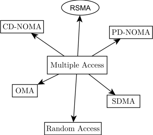
Rate Splitting Multiple Access (RSMA)is one of many possible techniques to manage the access of available resources for multiple users. Fig. 6 shows many possible techniques for multiple access. The focus of this article, RSMA, is encircled. Moreover, many articles in the literature compared RSMA with SDMA and Power Domain (PD)-NOMA, mainly because RSMA is a general framework that includes both techniques. Throughout this article, PD-NOMA will simply be referred to as NOMA. The OMA classification includes traditional multiple access techniques which are widely adopted like Time Division Multiple Access (TDMA), Code Division Multiple Access (CDMA), Frequency Division Multiple Access (FDMA), and OFDMA, while Space-Division Multiple Access (SDMA)is a technique to separate users spatially, to allow reuse of available resources like time and frequency. Furthermore, Code Domain (CD)-NOMA [100, 101] does not necessarily rely on superposition coding with successive interference cancellation (SC-SIC) as in PD-NOMA, and it includes Low Density Spreading (LDS)-CDMA, LDS-Orthogonal Frequency Division Multiplexing (OFDM), Sparse Code Multiple Access (SCMA), Pattern Division Multiple Access (PDMA), and Multi User Shared Access (MUSA). Lastly, the random access category includes schemes like ALOHA, and Carrier Sense Multiple Access (CSMA).
This article examines papers that explore the use of the RIS with RSMA [1, 2, 3, 4, 5, 6, 7, 8, 9, 10, 11, 12, 13, 14, 15, 16, 17, 18, 19, 20, 21, 22, 23, 24, 25, 26, 27, 28, 29, 30, 31, 32, 33, 34, 35, 36, 37, 38, 39, 40, 41, 42, 43, 44, 45, 46, 47, 48, 49, 50, 51, 52, 53, 54, 55, 56, 57, 58, 59, 60, 61, 62, 63, 64, 65, 66, 67, 68]. One paper was published in 2020 [1], followed by five papers in 2021 [2, 3, 4, 5, 6], 19 papers in 2022 [7, 8, 9, 10, 11, 12, 13, 14, 15, 16, 17, 18, 19, 20, 21, 22, 23, 24, 25], and more than 30 papers in 2023 [26, 27, 28, 29, 30, 31, 32, 33, 34, 35, 36, 37, 38, 39, 40, 41, 42, 43, 44, 45, 46, 47, 48, 49, 50, 51, 52, 53, 54, 55, 56, 57, 58, 59, 60, 61, 62, 63, 64]. Table I shows the inter-citations and the publication year for these articles in addition to the RS scheme and the type of the RIS. Selected keywords from each article are also listed. The articles are ordered according to their publication date, yet the order here is not an exact order of the first appearance of the article.
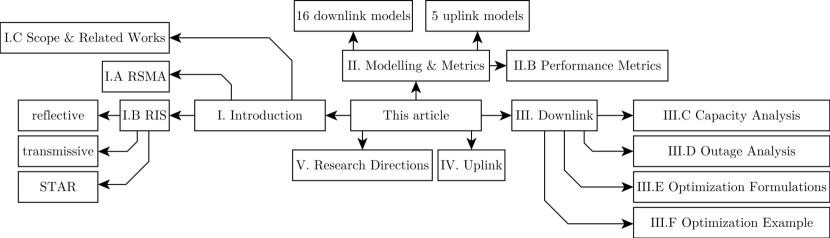
There are two publications close to the topic of this article [10, 13], and are described in Sections II-A and II-A, respectively. About 200 abbreviations are used in this article, some of them are listed in Table II. A survey on the RIS-assisted NOMA networks was published in 2022 [83], and it does not cite any of the articles [1, 2, 3, 4, 5, 6, 7, 8, 9, 10, 11, 12, 13, 14, 15, 16, 17, 18, 19, 20, 21, 22, 23, 24, 25, 26, 27, 28, 29, 30, 31, 32, 33, 34, 35, 36, 37, 38, 39, 40, 41, 42, 43, 44, 45, 46, 47, 48, 49, 50, 51, 52, 53, 54, 55, 56, 57, 58, 59, 60, 61, 62, 63, 64, 65, 66, 67, 68] in the focus of this paper. This article, however, focuses on RSMA. Since some articles discussed herein discuss covert communications, a survey on covert communication might be instructive [102]. Details on RIS [103] and STAR-RIS [98, 96] can be useful. An overview of the outline of this paper is depicted in Fig. 7.
| Cites | Year | Ref | Keywords | RS Scheme | RIS Type |
|---|---|---|---|---|---|
| - | 2020 | [1] | 3 Tx antennas, 3 RISs | 1L-RS | passive reflective |
| - | 2021 | [2] | cell-edge, on-off RIS | 2L-HRS | passive reflective |
| [1] | 2021 | [3] | discrete RIS | 1L-RS | passive reflective |
| - | 2021 | [4] | C-RAN, 4 BSs | multicommon | passive reflective |
| - | 2021 | [5] | cell-edge, on-off RIS | 1L-RS | passive reflective |
| - | 2021 | [6] | WMMSE | 2L-HRS | passive reflective |
| [1, 6, 5, 3] | 2022 | [7] | WMMSE, FC RIS | 1L-RS | passive reflective FC |
| [5, 1] | 2022 | [8] | cell-edge, SISO | 1L-RS | passive reflective 2D |
| [4, 1, 14] | 2022 | [9] | alternating CSI | ORS | passive reflective |
| [2] | 2022 | [10] | review | 1L-RS | passive reflective |
| [1, 3] | 2022 | [11] | RS at SU | cognitive-RSMA | passive reflective |
| [1, 5] | 2022 | [12] | correlated Rician | 1L-RS | passive STAR |
| [3, 2, 14, 4, 10, 6, 7, 5, 1] | 2022 | [13] | review | 1L-RS (& 2L-HRS) | passive reflective |
| [4, 1] | 2022 | [14] | C-RAN, user clustering | multicommon | passive reflective |
| [3, 13, 7, 2, 5] | 2022 | [15] | Cooperative RS | 1L-RS | passive reflective |
| [3] | 2022 | [16] | THz, SSA | 1L-RS | passive reflective |
| - | 2022 | [17] | SWIPT, secrecy rate | 1L-RS | passive STAR |
| [3, 1, 5] | 2022 | [18] | mmWave, clustering | multi-layer RSMA | passive reflective |
| [3, 26, 1, 5] | 2022 | [19] | UAV sans trajectory | 1L-RS | passive reflective |
| [3, 4, 7, 6, 1, 5] | 2022 | [20] | cell-edge, MISO | 1L-RS | passive reflective |
| - | 2022 | [21] | channel estimation | 1L-RS | passive reflective |
| - | 2022 | [22] | SWIPT, GA | 1L-RS | passive reflective |
| [3, 13, 5, 1, 7] | 2022 | [23] | short packet | 1L-RS | passive reflective |
| [3, 7, 5, 1] | 2022 | [24] | SWIPT, cascaded RISs | 1L-RS | passive reflective |
| - | 2022 | [25] | UAV, short packet | 1L-RS | passive reflective |
| [5, 2] | 2023 | [26] | UAV, vehicles | 1L-RS | passive reflective |
| [3, 1] | 2023 | [27] | Multicast | 1L-RS | passive reflective |
| [3, 1, 5] | 2023 | [28] | Covert Comm. | 1L-RS | passive reflective |
| [37] | 2023 | [29] | Improper Signalling | 1L-RS | passive reflective |
| - | 2023 | [30] | Cognitive Radio | single-user RS | passive reflective |
| [10] | 2023 | [31] | SINR, capacity analysis | 1L-RS | passive reflective |
| [3] | 2023 | [32] | URLLC | 1L-RS | active reflective |
| [24, 22, 1] | 2023 | [33] | SWIPT | 1L-RS | passive reflective |
| [3, 5] | 2023 | [34] | Opportunistic RIS | custom | passive reflective |
| [5, 1, 3] | 2023 | [35] | NLoS, Decoding order | 1L-RS uplink | passive reflective |
| [18, 1, 37, 6, 5, 13, 2] | 2023 | [36] | RIS elements grouping | 1L-RS | passive reflective |
| [5, 13] | 2023 | [37] | Improper Signalling | 1L-RS | passive ref. & STAR |
| - | 2023 | [38] | SIC-free | dual-polarized 1L-RS | passive reflective |
| [37, 6, 2, 5, 7, 10, 13] | 2023 | [39] | Overloaded | 1L-RS & TP & PP | passive reflective |
| [5, 3] | 2023 | [40] | Imitation Learning, DRL | 1L-RS | passive reflective |
| [40, 3] | 2023 | [41] | Imitation Learning, DRL | 1L-RS | passive reflective |
| [13, 1] | 2023 | [42] | FP, QCQP | 1L-RS | active reflective |
| [1, 13, 7] | 2023 | [43] | Resource Efficiency | 1L-RS & 2L-HRS | active reflective |
| [13, 3, 1, 7] | 2023 | [44] | DFAPN, THz, get CSI | 1L-RS | passive reflective |
| [4, 5, 14, 1, 6, 3, 7] | 2023 | [45] | PPO, SWIPT | 1L-RS | passive reflective |
| [35, 18, 20, 22] | 2023 | [46] | Outage, Nakagami-m | 1L-RS | passive reflective |
| [5, 7, 2, 4, 1, 3] | 2023 | [47] | Cognitive Radio | cognitive-RSMA | passive reflective |
| [13, 7, 2, 14, 5, 1] | 2023 | [48] | Cooperative | 1L-RS | passive reflective |
| [13, 1] | 2023 | [49] | Cognitive, Multiobjective | 1L-RS | transmissive |
| [1, 5, 3, 7, 22, 35, 18] | 2023 | [50] | 2 users uplink | single-user RS | passive reflective |
| [13, 5, 3, 1] | 2023 | [51] | NLoS | multi-layer RSMA | passive STAR |
| [1, 26] | 2023 | [52] | Covert Comm. | 1L-RS | passive reflective |
| [3, 1, 5] | 2023 | [53] | Coalition formation | 2L-RS | active reflective |
| [5] | 2023 | [54] | UAV: DF relay + RIS | 1L-RS | passive reflective |
| [5, 28, 20, 35, 12, 51, 53, 43] | 2023 | [55] | outage, diversity order | 1L-RS | active STAR |
| [12] | 2023 | [56] | Stochastic Geometry | 1L-RS | passive STAR |
| [13, 51, 12] | 2023 | [57] | Multifunctional RIS | 1L-RS | active STAR |
| [1] | 2023 | [58] | MIMO | 1L-RS | passive reflective |
| [14, 28] | 2023 | [59] | Covert Comm. | multicommon | passive reflective |
| [1, 5, 7, 3, 18, 20, 45] | 2023 | [60] | DDPG, uplink, mobility | 1L-RS | passive reflective |
| - | 2023 | [61] | WMMSE | 1L-RS | transmissive |
| [12, 51] | 2023 | [62] | Relaying &Dest. Groups | cooperative 1L-RS | passive STAR |
| [104] | 2023 | [63] | Beyond Diagonal | 1L-RS | passive reflective |
| [12, 51, 52] | 2023 | [64] | Eve, Nakagami-m | 1L-RS | passive STAR |
| - | 2024 | [65] | ISAC | 1L-RS | passive reflective |
| [1] | 2024 | [66] | Cell-edge, multicell | 1L-RS | passive reflective |
| [1, 7, 12, 51, 17, 18, 15, 20, 8, 5, 22, 45] | 2024 | [67] | PPO | 1L-RS | passive STAR |
| [18, 23, 1, 3, 54, 5, 13, 7] | 2024 | [68] | short packet, multi RIS | 1L-RS | passive reflective |
I-E Notes on Terminology
This subsection discusses general terms only. Some other acronyms that are specific to certain group of papers (like machine learning acronyms) are commented on later if necessary. Similarly, optimization-related acronyms are discussed later in Section III-B. Starting with the two main acronyms, Rate Splitting Multiple Access (RSMA)is consistently used by all authors except the three papers by Weinberger et. al. [4, 9, 14] which never mention RSMA and just use RS.
The second main term, can be IRS or RIS. IRS may suggest that only reflection capabilities are possible, while RIS can be interpreted to support both reflecting and transmitting surfaces. In fact, many authors emphasize these special capabilities and other features of the surfaces through terms like ARIS where the A stands for “Active” [55] or for “Aerial” [25, 54], Passive Reconfigurable Intelligent Surface (PRIS) [55], STAR [12, 17, 18, 34, 51, 67, 64], Simultaneously Transmitting/Reflecting Surface (STARS) [55], Active Simultaneously Transmitting/Reflecting Surface (ASTARS) [55], Passive Simultaneously Transmitting/Reflecting Surface (PSTARS) [55]. At any rate, in the focus of this paper, 36 papers use RIS and 20 papers use IRS, with a general trend of decreasing use of the latter over the duration of this study. To add to the complication, [67] uses RO-RIS and TO-RIS to indicate reflecting-only RIS and transmitting-only RIS. Moreover Aerial Inelligent Reflecting Surfaces (AIRS) [19] and No IRS (NIRS) [3] have been used.
URA is not used for uniform rectangular array except by [18]. Nonetheless, since URA can indicate Unsourced Random Access as mentioned by [66], it is probably better to keep Uniform Planar Array (UPA) for the planar RIS structure (or for the planar array structure at the BS as well). NGMA is a general term that can be used to include MA terms like RSMA, NOMA [105], and Unsourced Random Access (URA) [106]. A user is sometimes used to refer to a receiver terminal, or a pair of a transmitter and a receiver. This article uses the former definition. Short block length codes can be called Finite Block-Length (FBL)or Short Packet Communication (SPC)[12, 23]. Similarly, long block length codes can be called Infinite Block-Length (IBL)or Long Packet Communication (LPC)[23]. Throughout this article and all reviewed articles, RSMA refers to Rate Splitting Multiple Access, and not Resource Spread Multiple Access.
| CU | Cognitive User |
|---|---|
| DDPG | Deep Deterministic Policy Gradient |
| DEP | Detection Error Probability |
| DFAPN | Deep unFolding Active Precoding Network |
| DF | Decode-and-Forward |
| DFT | Discrete Fourier Transform |
| DNN | Deep Neural Network |
| DoF | Degrees of Freedom |
| DPC | Dirty Paper Coding |
| DRL | Deep Reinforcement Learning |
| EE | Energy Efficiency |
| EH | Energy Harvesting |
| ES | Energy Splitting |
| FBL | Finite Block-Length |
| FC | Fully-Connected |
| FD | Full-Duplex |
| FDMA | Frequency Division Multiple Access |
| FU | Far-User |
| HMIMO | Holographic MIMO |
| HRS | Hierarchical RS |
| IFBL | Infinite Block Length |
| IQI | I/Q Imbalance |
| IR | Information Receiver |
| ISAC | Integrated Sensing And Communication |
| JFI | Jain’s Fairness Index |
| LoSC | Level of Supportive Connectivity |
| LPC | Long Packet Communication |
| LP | Linear Precoding |
| LWA | Leaky-Wave Antennas |
| MAR | Minimum Achievable Rate |
| MLP | MultiLayer Perceptron |
| MMF | Max-Min Fairness |
| MM | Majorization-Minimization |
| MMSE | Minimum Mean Square Error |
| MRC | Maximum Ratio Combining |
| MR | Minimum Rate |
| MRT | Maximum Ratio Transmission |
| MSD | Mean Square Distance |
| MSE | Mean Square Error |
| MS | Mode Switching |
| NOMA | Non-Orthogonal Multiple Access |
| OP | Outage Probability |
| ORS | Opportunistic Rate Splitting |
| PGS | Proper Gaussian Signalling |
| PP | Power Partitioning |
| PS | Power Splitting |
| RE | Resource Efficiency |
| RIS | Reconfigurable Intelligent Surface |
| RPSD | Random Phase-Shift Design |
| RRN | RIS Reflecting Network |
| RS | Rate-Splitting |
| SE | Spectral Efficiency |
| SR | Secrecy Rate |
| SOP | Secrecy Outage Probability |
| SPC | Short Packet Communication |
| SRE | Smart Radio Environment |
| SSR | Sum Secrecy Rate |
| STAR | Simultaneously Transmitting and Reflecting |
| SWIPT | Simultaneous Wireless Information and Power Transfer |
| TARC | Transmission and Reflection Coefficients |
| TCA | Tightly Coupled antenna Arrays |
| TIN | Treating Interference as Noise |
| TP | Time Partitioning |
| TRIS | Transmissive RIS |
| TS | Time Switching |
| UER | Untrusted Energy Receiver |
| UM | Ultra Massive |
| UPA | Uniform Planar Array |
| URA | Unsourced Random Access |
| WCSSR | Worst-case Sum Secrecy Rate |
| WESR | Weighted Ergodic Sum Rate |
| WMMSE | Weighted Minimum Mean Square Error |
| WMSE | Weighted Mean Square Error |
| WSR | Weighted Sum-Rate |
Notations: () is the matrix (vector) channel from the transmitter to the th user, and () is its conjugate transpose (or hermitian). denotes the linear precoder at the transmitter, while denotes the power budget at the transmitter. is the trace of the square matrix . denotes the mathematical expectation. is the set of all complex-valued dimensional matrices. The six integers , , , , , are explained before the beginning of Section II-A. Special notation is adopted for Table IV and is explained before the table in Section III-A.
II System Modelling and Performance Evaluation Metrics
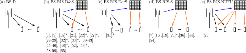
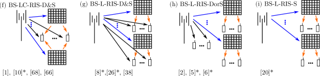
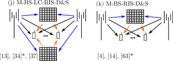
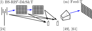
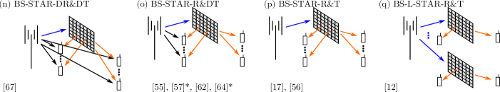
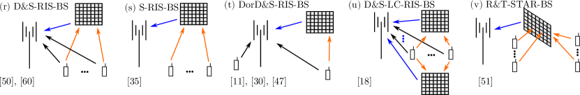
This section describes essentials for modelling different components of the RIS-assisted RSMA wireless communications link. Most of the works focus on the DL scenario [1, 2, 3, 4, 5, 6, 7, 8, 9, 10, 12, 13, 14, 15, 16, 17, 19, 20, 21, 22, 23, 24, 25, 26, 27, 28, 29, 31, 32, 33, 34, 36, 37, 38, 39, 40, 41, 42, 43, 44, 45, 46, 48, 49, 52, 53, 54, 55, 56, 57, 58, 59, 61, 62, 63, 64, 65, 66, 67, 68], and a few focus on the Uplink (UL) scenario [11, 18, 30, 35, 47, 50, 51, 60]. Figs. 8, 9, 10, 11, 12 provide a general classification of the downlink models used by different authors, while Fig. 13 shows uplink models. Note that the classification is not fully detailed, which means that some authors might assume further details that are not depicted in these figures. Whenever special attention is required, an asterisk is used following the citation of the article in the figure. For example, two time slots are used in [15], and the RIS is mounted on a Unmanned Aerial Vehicle (UAV) in [19]. Throughout this paper, models will be referred to by their name without the figure number. Models (b) through (e) feature a single BS and a single (reflecting) RIS, (f) through (i) feature a single BS and multiple RISs, (j) features multiple BSs and multiple RISs, (k) features multiple BSs and a single RIS, (l) features a single BS and two RISs in cascade, (m) features a feed antenna next to a transmissive RIS, (n) through (p) feature a single BS and a single STAR-RIS, (q) features a single BS and multiple STAR-RISs, and (r) through (v) features uplink models.
For the ease of exposition, the number of elements will be denoted as follows.
-
•
The number of BSs is , and the number of antennas per BS is .
-
•
The number of RISs is , and the number of elements per RIS is .
-
•
The number of users is , and the number of antennas per user is .
The values for these parameters are used as headers in Table III which summarizes the models keeping the notations of the authors. It also shows whether DL or UL channels were used, as well as CSIT assumption. The first subsection in this section covers the models, and the second subsection covers the performance evaluation metrics.
| Ref | Ch | Imperfect | BS | RIS | Users | ||||
|---|---|---|---|---|---|---|---|---|---|
| CSIT | Model Class | , UPA? | , UPA? | ||||||
| [1] | DL | f) BS-LC-RIS-D&S | |||||||
| [2] | DL | ✓ | h) BS-L-RIS-DorS | y | |||||
| [3] | DL | b) BS-RIS-D&S | |||||||
| [4] | DL | k) M-BS-RIS-D&S | |||||||
| [5] | DL | ✓ | h) BS-L-RIS-DorS* | ||||||
| [6] | DL | ✓ | h) BS-L-RIS-DorS* | ||||||
| [7] | DL | d) BS-RIS-S | |||||||
| [8] | DL | ✓ | g) BS-L-RIS-D&S* | ||||||
| [9] | DL | ✓ | b) BS-RIS-D&S | ||||||
| [10] | DL | f) BS-LC-RIS-D&S* | |||||||
| [11] | UL | t) DorD&S-RIS-BS | |||||||
| [12] | DL | ✓ | q) BS-L-STAR-R&T | ✓ | |||||
| [13] | DL | ✓ | j) M-BS-LC-RIS-D&S | ||||||
| [14] | DL | ✓ | k) M-BS-RIS-D&S | ||||||
| [15] | DL | b) BS-RIS-D&S* | |||||||
| [16] | DL | d) BS-RIS-S | ✓ | ||||||
| [17] | DL | ✓(UER) | p) BS-STAR-R&T | ||||||
| [18] | UL | u) D&S-LC-RIS-BS | y | ||||||
| [19] | DL | d) BS-RIS-S | |||||||
| [20] | DL | i) BS-L-RIS-S* | |||||||
| [21] | DL | ✓ | b) BS-RIS-D&S | ||||||
| [22] | DL | ✓ | b) BS-RIS-D&S* | ||||||
| [23] | DL | e) BS-RIS-NUFU | |||||||
| [24] | DL | l) BS-RIS2-D&S&T | |||||||
| [25] | DL | ✓ | d) BS-RIS-S* | ||||||
| [26] | DL | ✓ | g) BS-L-RIS-D&S* | ||||||
| [27] | DL | b) BS-RIS-D&S* | |||||||
| [28] | DL | b) BS-RIS-D&S | |||||||
| [29] | DL | b) BS-RIS-D&S | |||||||
| [30] | UL | t) DorD&S-RIS-BS | |||||||
| [31] | DL | ✓ | c) BS-RIS-DorS* | ||||||
| [32] | DL | b) BS-RIS-D&S* | |||||||
| [33] | DL | b) BS-RIS-D&S* | |||||||
| [34] | DL | j) M-BS-LC-RIS-D&S* | |||||||
| [35] | UL | s) S-RIS-BS | |||||||
| [36] | DL | d) BS-RIS-S | |||||||
| [37] | DL | j) M-BS-LC-RIS-D&S* | |||||||
| [38] | DL | g) BS-L-RIS-D&S | |||||||
| [39] | DL | ✓ | b) BS-RIS-D&S | ||||||
| [40] | DL | b) BS-RIS-D&S | |||||||
| [41] | DL | b) BS-RIS-D&S | |||||||
| [42] | DL | b) BS-RIS-D&S | |||||||
| [43] | DL | b) BS-RIS-D&S | |||||||
| [44] | DL | ✓ | d) BS-RIS-S | ✓ | ✓ | ||||
| [45] | DL | b) BS-RIS-D&S | |||||||
| [46] | DL | ✓ | b) BS-RIS-D&S | ||||||
| [47] | UL | t) DorD&S-RIS-BS | |||||||
| [48] | DL | b) BS-RIS-D&S* | |||||||
| [49] | DL | m) Feed-T | y | ||||||
| [50] | UL | r) D&S-RIS-BS | |||||||
| [51] | UL | v) R&T-STAR-BS | |||||||
| [52] | DL | b) BS-RIS-D&S | |||||||
| [53] | DL | ✓ | b) BS-RIS-D&S* | y | |||||
| [54] | DL | d) BS-RIS-S | |||||||
| [55] | DL | o) BS-STAR-R&DT | |||||||
| [56] | DL | p) BS-STAR-R&T | |||||||
| [57] | DL | o) BS-STAR-R&DT* | |||||||
| [58] | DL | ✓ | b) BS-RIS-D&S | ✓ | |||||
| [59] | DL | b) BS-RIS-D&S | |||||||
| [60] | UL | ✓ | r) D&S-RIS-BS | ✓ | |||||
| [61] | DL | ✓ | m) Feed-T | ||||||
| [62] | DL | o) BS-STAR-R&DT | |||||||
| [63] | DL | k) M-BS-RIS-D&S* | |||||||
| [64] | DL | o) BS-STAR-R&DT* | |||||||
| [65] | DL | b) BS-RIS-D&S ∗ | |||||||
| [66] | DL | f) BS-LC-RIS-D&S | |||||||
| [67] | DL | n) BS-STAR-DR&DT | |||||||
| [68] | DL | ✓ | f) BS-LC-RIS-D&S |
II-A Models
BS-D
There is no RIS in this model, but it serves as a baseline in two ways: 1) using traditional beamforming techniques such as Weighted Minimum Mean Square Error (MMSE) [107] or 2) using RSMA only without RIS [73]. This subsection describes the basic system model. Note that a matrix (denoted by capital bold letter) is used for the channel to the user, despite the prevailing assumption so far in the literature that a user is equipped with a single antenna, in which case the matrix is reduced to a vector. The -th user receives [107]
| (1) |
for the RIS-free, RSMA-free model, where is the direct channel from the BS to the user which does not need to be Line-of-Sight (LoS) (e.g. it could be a Rayleigh fading link), is the symbol transmitted by the BS, and is the Additive White Gaussian Noise (AWGN) at the -th receiver. In addition, the transmitted symbol is a combination of encoded symbols that are intended for different users, and that combination is done linearly through a linear precoder represented by . That is . Modelling and analysis of the 1L-RS will be discussed in Section III-E.
BS-RIS-D&S
This model is a simple downlink model and is useful to draw essential conclusions. It is the most studied model among all the models reviewed in this paper. This model assumes a single reflecting RIS that can see all users, while the BS still has a direct link to all users. Therefore, each user can receive a direct signal from the BS and a reflected signal from the RIS. This model is adopted in [3, 9, 15, 21, 22, 27, 28, 29, 32, 33, 39, 40, 41, 42, 43, 45, 46, 48, 52, 53, 58, 59, 65]. In [3], discrete RIS phase shifts are considered, and 2 to 5 users are considered in the simulation study. A two-user system is considered in [9] and the CSI is alternated between coherence blocks. In [21], a single-antenna BS is assumed to serve multiple single-antenna users, and two users are considered in their simulation study. Users in [27] are grouped into multicast groups, where each group gets the same common and private messages. Improper Gaussian Signaling (IGS)is considered in [29], in addition to the possible I/Q imbalance at the receivers. A single-antenna BS serves single-antenna users in [46], and an -element RIS assists the transmission. Perfect CSI is assumed in the analysis, and the impact of imperfect CSI is examined in the simulation study.
In [40] and the later journal article [41], a Virtual Reality (VR) streaming system is considered where the achievable rate of the video is to be maximized. They employ imitation learning and actor-critic in the solution of the optimization problem.
An active RIS is considered in [42], and two users are assumed in the simulation study. A UPA active RIS is also examined in [53], where the authors maximize the minimum rate and utilize 2L-RS. A hybrid antenna array is utilized at the BS with digital and analog precoding. In addition, users are grouped using coalition formation.
In [32], an active RIS is considered for URLLC transmission. Hence, short packets are considered. This is motivated by the fact that the common rate of the RSMA is limited by the rate support by the user having the lowest channel quality. They consider an underloaded system where the number of users is less than the number of antennas.
The system proposed in [15, 48] builds upon the concept of cooperative-RSMA [87] to investigate the effect of incorporating the RIS, and this combination proves useful. Two users are considered in the system model: a far user and a near user. The system utilizes two time slots that are not necessarily equal. In the first time slot, the BS encodes the signal using the 1L-RS protocol for both the near and the far user. The near user adopts a Non-regenerative Decode-and-Forward (NDF) relay mode to transmit the common stream once again to the far user at the second time slot. Hence, the far user receives two copies of the common stream, one from the BS, and the other from the near user. A multi-user scenario is not considered.
In [52], a transmitter, an RIS, 2 (NOMA) users, and 1 user (eavesdropper or warden) are considered. Despite the two legitimate users being called NOMA in [52], their description fits 1L-RSMA. They investigate Detection Error Probability (DEP) (which is basically a hypothesis testing formulation), and covert communication rate. For DEP, they use the gamma distribution to model the cascaded channel and then the DEP expression is readily available. They discuss the effects of nulling one of the legitimate streams (that is, the effects of rate splitting), as well as the effect of the RIS with different number of elements. Direct channels from the transmitter to the users are assumed to experience Rayleigh fading, while channels through the RIS experience Rician Fading.
In [28], A system with Legitimate Users (LUs) and potential eavesdroppers is considered. The authors study the two-legitimate-users system in addition to exploring the performance of three schemes for up to 6 LUs. The objective is to maximize the minimum Secrecy Rate (SR), and they show the advantage of RSMA and RIS over NOMA and MU-LP. In [59], covert communications is considered where they maximize the covert rate to the covert user while maintaining a minimum rate for an ordinary user. The warden is the third user in the system.
The authors in [39] focus on the overloaded case where they assume that the number of users is larger than the number of antennas at the BS. They consider two groups in the system model, the first group consists of users and is served through RSMA, while the other group contains the extra users (more than the number of antennas at the BS) is served through OMA. In fact, they employ Time Partitioning (TP)-RSMA and Power Partitioning (PP)-RSMA. However, their model figure seems misleading as the direct link is considered in the analytical analysis. Hence, model (b) is used for classification.
The authors in [43] present an RSMA network model with a single active RIS and a single BS. They assume an active RIS which requires neither a Digital-to-Analog Converter (DAC) nor an Analog-to-Digital Converter (ADC), and just utilizes power amplifiers and phase shifting circuits. In the simulation study, the BS is 10m high as well as the RIS surface. The users are assumed to be closer to the RIS.
A Simultaneous Wireless Information and Power Transfer (SWIPT) system is considered in [33], and the performance is compared to NOMA and SDMA. A linear model is used for the energy harvester. In addition, in the simulation study, the Energy Receivers (ERs) are located near the RIS contrary to the Information Receivers (IRs). Another correspondence considering the SWIPT system model is [22]. At each user, a power splitter delivers power to the Energy Harvesting (EH) and information to the information decoder according to a splitting ratio. A non-linear EH model is adopted, and their objective is to minimize the transmit power while ensuring a minimum rate and a minimum harvested energy. Imperfect CSI is also considered. The SWIPT concept is also explored in [45]. The transmitter employs 1L-RS, and a single reflecting RIS is used. Each user has a power splitter after its receiving antenna that feeds two components: the information decoder and the energy harvester. With RSMA employed, the information decoder first decodes the common stream, removes it by SIC, then decodes the private stream. Furhtermore, they adopt a non-linear EH model [108]. They use a Proximal Policy Optimization (PPO)-based Deep Reinforcement Learning (DRL) method to maximize the EE. The maximization of EE will be discussed in Section III-E2.
In [58], users are assumed to have multiple antennas, which sets this article different. An MMSE combiner is considered at the receiver, as well as the beamforming at the transmitter. However, the details of optimizing the common rate allocation and the RIS phase shifts are not presented. Furthermore, the simulation study does not consider single-antenna users for comparative performance study.
In [65], an Integrated Sensing And Communication (ISAC) system is considered, where the BS does both communications and sensing of a target without using a special radar sequence. This study was motivated by previous studies on an ISAC system either in an RIS-assisted system, or an RSMA-enabled system. In the RIS-assisted ISAC system, SDMA is restricting the performance because it does not fully exploit the extra path created by the RIS. In addition, the gain of RSMA can diminish in severe fading. Hence, the authors in [65] study the synergy of RSMA and RIS in a downlink MISO system with a single target, and show the gains of both RSMA and RIS on the radar Signal-to-Noise Ratio (SNR).
BS-RIS-DorS
This model differs from the previous one ‘b) BS-RIS-D&S’ in the assumption that some users cannot receive the signal from the BS, and hence can only be served through the RIS. Meanwhile, the users served by the BS do not receive any signal from the RIS. Only a single paper studies this model [31], where the author focuses on the capacity analysis for two users, one served by the BS directly and the other served though the RIS only. Additional information can be found in Section III-C.
BS-RIS-S
This model is a simple modification of ‘b) BS-RIS-D&S’ where the direct link from the BS to the users is blocked. Hence, there is a single link from the BS to the users which go through the RIS, that is the secondary link. This model is examined by [7, 16, 19, 25, 36, 44, 54]. A fully-connected RIS is considered in [7]. A two-user system is considered in [19] where a UAV-mounted RIS provides the link to the blocked users. The UAV circulates a path of known radius with a constant velocity. The authors in [36] present a grouping scheme for the impedance network of the RIS.
In [25], an RIS is mounted on a UAV along with a Full-Duplex (FD)-Decode-and-Forward (DF) relay to provide a channel link between a BS and users. The BS and the users are equipped with a single-antenna each. The relay decodes then re-encodes the signal using RSMA. A similar model is also studied by the same authors in [54] with more analyses.
References [16] and [44] consider terahertz models. In Terahertz (THz) networks, the channel matrix can be modelled in a deterministic, or a statistical, or a hybrid way. The first one requires detailed knowledge of the specific installation site, while the second one can provide adequate model with some channel statistics [109]. A popular model of the second type is the Saleh-Valenzuela (S-V) channel model [110]. THz channels show stronger directivity compared to Millimeter Wave (mmWave) and Centimeter Wave (cmWave). Therefore, it is reasonable to use a rank-one matrix to model the channel, since more than 90% of path gain is from the LoS link [109]. Consequently, shadowing will severely degrade the channel quality, and RIS-assisted link may be valuable. THz signals, however suffer from degraded channel conditions due to molecular absorption loss and free-spreading loss[109]. The former can generally be expressed as an exponential loss where is the distance and is dependent on the frequency, temperature, and pressure and can be obtained from the HITRAN2012 database [111]. The latter is proportional to the squared frequency and squared distance[109]. These significant losses support the use of Ultra Massive (UM)-MIMO to provide a large gain to cover these losses.
BS-RIS-NUFU
This model is similar to ‘c) BS-RIS-DorS’ except that the near users can also receive a signal from the RIS. This model is studied by [23]. The main focus of [23] is on SPC. The idea of SPC is to reduce the packet size to achieve low latency at a low error probability, say, less than a millisecond with error probability less than . The authors claim 80% improvement in achievable rate for SPC with RIS. In addition, motivated by the energy efficiency of RSMA over NOMA and SDMA in general, they propose that the RIS-assisted RSMA network can be suitable for SPC maintaining low error probability as well as being energy efficient, especially for Far-Users (FUs) that are essentially blocked from any direct link to the BS. Their aim is optimizing the EE. EE maximization is discussed in Section III-E2.
BS-LC-RIS-D&S
This model is an extension of ‘b) BS-RIS-D&S’ where multiple RISs are possible. All RISs serve the same group of users. The users can also receive a signal directly from the BS. In this paper, stands for the number of RISs, and that is the ‘L’ in the title of this model. In addition, stands for the common users. In other words, the same group of users can have links from the BS. This model is used by [1, 10, 68, 66]. The authors in [1] consider a single BS, along with multiple RISs and multiple users. For the simulation study, they consider 3 RISs, 3 users, along with 3 transmit antennas at the BS.
The article [10] is an overview of the potential advantages of RIS-assisted RSMA networks. They start by noting the merits of SDMA in providing the potential to reuse frequency over different spatial directions, yet this could be a source of interference to users in the same spatial direction. Next, they motivate RSMA by the robustness of CSI imperfection compared to other OMA techniques, as well as NOMA. In particular, they pose 1L-RS as a middle strategy between precoding (Zero Forcing (ZF)) at the transmitter, and full SIC at the receiver. In addition, they also note that all private messages to the users are superimposed in the power domain to the combined message. Hence, each user does a single SIC step. They also mention the common dyadic channel model for communications links through the RIS, and note possible construction materials for the RIS like diodes and liquid crystals. More importantly, they note three possible improvements of the RIS-assisted RSMA network, namely: rate enhancement, robustness to imperfect CSI, as well as robustness to imperfect SIC. They illustrate each point with a figure based on a narrow-band, two-user, two-RIS system model (where each user is served by a dedicated RIS). In the first figure, they show the advantage of the extra DoF provided by the RIS link, which enhance the optimization of the common rate of the RSMA to meet the required common rate. Without the RIS, this problem is somewhat difficult or infeasible. In the second figure, they show that RSMA and RIS-RSMA suffer less from the residual SIC errors compared to NOMA and RIS-NOMA. Comparison to TDMA and RIS-TDMA is also presented. In the third figure, the advantage of RIS-RSMA over RIS-TDMA and RIS-NOMA is shown in another realistic scenario, imperfect CSI. Finally, they note possible future advantages of RIS-assisted RSMA networks in the UAV, high frequency, and Low Earth Orbit (LEO) satellites networks. This note is highly motivated by the robustness to CSI imperfection, which happen in these systems due to various reasons. In the focus of this paper, some articles considered UAVs [25, 26, 54, 63, 19] and others considered THz networks [16, 44]. More on the THz networks can be found in Section II-A (few paragraphs earlier).
In [66], a mutli-cell multi-RIS and multi user system is considered where the authors maximize the EE for cell-edge users. Users are divided intro groups and, within each group, users are assumed to request the same information from the BS. In the simulation study, three BSs, three RISs and six users in three groups are considered. In addition, the channel between the BS and the users is assumed to follow Rayleigh distribution which implies non-dominant LoS link in an urban micro cell environment with a path loss of where . Furthermore, the channel between the BS and the RIS however, is assumed to follow Rician distribution suggesting a dominant LoS path in an urban macro cell environment with path loss . Both path loss expressions assume a carrier frequency around 2.4GHz. [112, Table B.1.2.1-1]
A URLLC system is studied in [68]. Slow fading channels and fixed RIS deployment are considered. It is assumed that the BS has perfect CSI, in addition to the RIS. However, the impact of channel estimation errors is investigated in the simulation study. Each mobile broadband user has a target Packet Error Probability (PEP) that must be satisfied in the throughput optimization.
BS-L-RIS-D&S
This model is a modification of the previous one ‘f) BS-LC-RIS-D&S)’ where the set of users served by each RIS is different. Meanwhile all groups of users can have a direct link with the BS. Hence, the ‘C’ is dropped from the title of this model. This model is examined by [8, 26, 38]. In [8], a single-antenna BS serves multiple single-antenna cell-edge users. Each user is associated to a dedicated RIS, and can also have a direct link to the BS. Optimal and discrete phase shifts are considered, and channels are assumed to be Nakagami-m distributed. A similar article with multi-antenna BS is [20] which assumes no direct paths to the users, hence classified in ‘i)BS-L-RIS-S’. A vehicular network is considered in [26], where a single-antenna UAV serves vehicles. The vehicles use the same spectrum and suffer from co-channel interference. In the simulations study, they assume a two-lane road and a UAV flying at a constant speed. The operating frequency is assumed to be 240 MHz. The authors in [38] utilize polarization multiplexing for the common and private rates to use RS without SIC at the receivers.
BS-L-RIS-DorS
Following the same logic in separating users into groups as done from the model ‘f) BS-LC-RIS-D&S’ to the model ‘g) BS-L-RIS-D&S’, this model assumes that the BS serves a group of users that is separate from the groups served by each RIS. Hence, each user receives a single message, either through the direct link from the BS, or through the secondary link from the RIS. This model is used by [2, 5, 6]. The authors in [2] utilize an on-off scheme for the RIS phase shifts and study the 2L-HRS. They derive the outage probability for cell-edge and near users. In [5], the closed-form expressions of the Outage Probability (OP) for Near-User (NU) and cell-edge user (CEU) are derived, and the effect of the number of the RIS elements on the outage behaviour for CEU is explored, and they show performance gains over a DF-RS scheme and RIS-NOMA scheme. In addition, in [6], the rate region for RIS-assisted RSMA is shown and compared to that of RIS-assisted NOMA.
BS-L-RIS-S
This model is another simplification from the previous model ‘h) BS-L-RIS-DorS’, where the group of users served exclusively by the BS is non-existent. This model is examined by [20] where a multi-antenna BS serves multiple cell-edge users though a dedicated RIS to each user. Direct links between the BS and the users are assumed to be weak and are ignored. Elements of each RIS are divided into groups equal to the number of transmission antennas at the BS. Channels are Rayleigh distributed, and discrete phase shifts are considered for the RIS.
M-BS-LC-RIS-D&S
This model assumes BSs and RISs, where and are used in this paper to denote the number of BSs and RISs respectively. This model is similar to ‘f) BS-LC-RIS-D&S)’ with the support of multiple BSs. This model is used in [13, 34, 37]. The first article [13] is described in the next paragraph. The authors in [34] assume a Coordinated Multiple Points (CoMP) system. In [34], some users are blocked by an obstacle and do not get a direct link to any BS. Channels through the RISs are assumed to follow the Nakagami- distribution while channels without the RIS follow the exponential distribution. Few RISs are chosen to serve some users. It is also assumed that the number of BSs (or access points) are larger than the number of the users. In the third article [37], a multicell MIMO model is used where users can receive signals from neighbouring cells. A motivation for this model is that it is one of the most practical scenarios.
The aim of [13], which is part of a three-article tutorial series on RSMA, is to motivate the integration of RSMA and RIS. They briefly note some advantages of RSMA including enhanced spectral efficiency, robustness to CSI imperfection, and SIC errors, as well as latency and mobility. In addition, they also note the merits of the RIS (e.g. passive, cheap, and configurable). Furthermore, they note that the RIS can enhance the system by providing extra links, while making CSI estimation more difficult, which is an opportunity to use RSMA which is known for its robustness to CSI errors, even with the simplest form of RSMA: 1L-RS. In the paper, the models of the two most common schemes of RSMA, namely, 1L-RS and 2L-RS, are mentioned. In addition, the authors mention the three architectures of RIS, namely, single-connected, block connected, and fully-connected architectures. They argue that this multi BS model (termed as ‘j) M-BS-LC-RIS-D&S’ in this paper) serves as a general framework for existing articles at the time, namely,
Furthermore, [13] provides a rate region plot assuming a single BS and a single RIS. That is model ‘b) BS-RIS-D&S’ in this paper. The rate region provided by [13] considers both perfect and imperfect CSI, and shows consistent advantage of RSMA over NOMA and SDMA, or at least similar level of performance as SDMA for some rate pairs in the perfect CSI condition.
M-BS-RIS-D&S
This model is a simplification of the previous one ‘j) M-BS-LC-RIS-D&S’ where only a single RIS remains in the model. This model is used by [14] and the earlier conference version [4], in addition to [63]. A Cloud Radio Access Network (C-RAN) network is used by [4, 14], where multiple BSs can serve the same user, and the BSs are all connected to a central processor. The C-RAN is motivated by the cooperative interference reduction, which can ultimately improve the transmission rates at the same power. The work in [14] adopts the RS approach of [113]. In particular, the central processor splits the messages and then distributes the splitted messages to the desired Remote Radio Units (RRUs). For the simulation study, they assume noise power spectral density of -169 dBm/Hz and the path loss model for 2GHz [112, Table A.2.1.1.2-3]. On the other hand, [63] is using multiple UAVs as BSs.
BS-RIS2-D&S&T
This model is special compared to the previous models. In this model, two RISs are assumed in cascade. Meanwhile, the users can still receive a signal from the BS directly, or from the first RIS, in addition to the signal from the second RIS. There is only a single paper in this class [24], where the authors aim to maintain a minimum power delivery and rate to multiple users through a double (cascade) RIS system. Building on top of (1), an extra factor denoting the Power Splitting (PS) ratio for the th user is multiplied by the channel which include 4 paths between the BS and the th user:
| (2) | ||||
where , , and are the channels to the single antenna user and are ; and are both diagonal with unit-norm constraints; is the channel from the first RIS to the second RIS; Finally, and are the channels from the BS to the first and second RISs. In summary, the four links to each user are: a direct link to the BS, a link with double reflection through both RISs, and a link with a single reflection through either RIS.
Feed-T
It was pointed out [92] that the RIS may be advantageous in the near field. This model assumes a Transmissive Reconfigurable Intelligent Surface (TRIS)in the near field of a transmitting antenna at the BS, and is used by [49, 61]. This is quite an uncommon idea is to utilize a UPA Transmissive Reconfigurable Intelligent Surface (TRIS) in the near field (separation less than the Rayleigh distance) of a horn antenna to form a Cognitive Base Station (CBS) [49]. That is, a TRIS is used as a BS in a cognitive radio network. The TRIS is a UPA, and CSIs of Primary Users (PUs) and Cognitive Users (CUs) are assumed to be available at the transmitter.
In [61], a TRIS is placed in front of an antenna at the transmitter in a MISO-BC channel with users. The RIS has sub-arrays and each array has elements. With sub-arrays, the performance is equivalent to an -antenna system. Yet, the transmissive RIS system is cheaper and consumes less power. The authors do not consider the channel between the transmit antenna and the RIS, and they consider that each sub-array of the RIS as a transmitter, therefore, the received signal at the th user is
| (3) |
where , and it is assumed that , and is a linear combination of messages weighted by the transmit power and RIS coefficients according to the 1L-RS protocol.
BS-STAR-DR&DT
This model and the next three models consider a STAR-RIS. In this model, all users (before and behind the STAR-RIS surface) can get a direct link from the BS. That is, users in the transmit-domain of the STAR-RIS surface as well as users in the reflect-domain of the STAR-RIS surface can ‘see’ the BS. This model is examined in [67] where the authors utilize a PPO-based algorithm for sum-rate maximization.
BS-STAR-R&DT
This model is a simplification of the previous model ‘n) BS-STAR-DR&DT’, where only the users in the reflect-domain of the STAR-RIS can get a direct link from the BS. While the users in the transmit-domain of the STAR-RIS are only served through the surface. This model is considered in [55, 57, 62, 64]. An active STAR-RIS system is studied in [55], and compared to the passive STAR-RIS. All channels are assumed to be Rician channels. A multi-functional RIS is proposed in [57] which retains the full space coverage like the STAR-RIS, in addition to resolving the problem of double-fading attenuation. A STAR-RIS is assumed in [62] along with cooperative RS and the authors maximize the worst rate. The authors in [64] assume two Legitimate Users (LUs): Bob and Grace, one transmitter: Alice, one STAR-RIS, and one Eve. Nakagami- channels are considered. The RIS’s phase shifts uncertainty [114] as well as deliberate fading of the signal towards the eavesdropper can be useful in achieving covert communications.
BS-STAR-R&T
This model is a simplification of the previous one ‘o) BS-STAR-R&DT’, where no users have a direct link from the BS, and all users are served exclusively through the STAR-RIS. This model is studied by [17, 56]. In [17], a BS communicates with IRs in the transmission half-space of the STAR-RIS as well as Untrusted Energy Receivers (UERs) in its reflection half-space. All users are equipped with a single antenna, and no direct link from the BS to any user. UERs are considered potential eavesdroppers, and their CSIT is unknown, unlike that of the IRs. Therefore, the primary objective is to maximize the Worst-case Sum Secrecy Rate (WCSSR) while maintaining a minimum sum energy for the UERs. In [56], Stochastic geometry tools are employed to study the outage probability. Both ES and MS modes are studied, along with Rician channels. The users are assumed to be distributed according to a Poisson point process (PPP).
BS-L-STAR-R&T
This model assumes multiple () STAR-RIS surfaces, and that each surface serves two users: one in the reflect-domain, and the other in the transmit-domain. This model is assumed in [12], with a pair of users served by each STAR-RIS. The STAR-RIS is assumed to be a UPA. The inter-element spacing is studied, along with ES mode and MS mode. In addition, the channels at the STAR-RIS are assumed correlated.
D&S-RIS-BS
Contrary to all previous models, this model and the next four models are uplink models. This model is similar to ‘b) BS-RIS-D&S’, except that the users are transmitting to the BS. That is, the BS can receive a direct signal from each user in addition to the reflected signal through the RIS. This model is assumed in [50, 60]. In [50], two users are assumed where a single user does RS. In [60], all users perform RS and are assumed to be moving with a speed of m/s in the system level simulation. In addition, the BS is assumed to have a Uniform Linear Array (ULA) of antennas and the RIS is formed of a URA.
S-RIS-BS
This model is a simplification of the previous one, where the BS only gets a single signal from each user through the RIS. This model is used in [35] where the RIS is vital in supporting the users with no LoS.
DorD&S-RIS-BS
This model is simple despite the complicated-looking title. In this model, the BS either receives a direct signal from the user, or receives a direct and a reflected signal from the user. This model is studied in [11, 30, 47]. The RIS assists the secondary user which performs RS in [11], which they term cognitive-RSMA. Similar cognitive-radio-inspired systems are presented in [30] and [47].
D&S-LC-RIS-BS
This model is similar to ‘f) BS-LC-RIS-D&S’, but in the uplink setting. In this model, the BS can have links from each user. This model is examined in [18] where a mmWave system is considered and users are dynamically clustered using -means clustering before optimizing the resource allocation.
R&T-STAR-BS
This model is similar to ‘p) BS-STAR-R&T’, but in the uplink setting. That is, users communicate with the BS exclusively through the STAR-RIS. This model is used by [51] where the authors focus on improving the spectral efficiency, fairness, and coverage probability for dead-zone users. A phase-shift coupled STAR-RIS is assumed.
II-B Performance Metrics
This section presents a few performance metrics that were used by different authors. However, most authors utilize the main objective function such as WSR for comparison and performance evaluation. Different objective functions are discussed in the downlink section, in addition to WSR for the uplink section, Section IV.
II-B1 Jain’s Fairness Index (JFI)
When the users are divided into groups, and the rate of each group is , the Jain’s Fairness Index (JFI) is defined as [115]
where . For example, the highest possible fairness can be achieved when all group rates are equal. When the JFI is 0.2, for example, then the system is unfair to 80% of the users. This index is used by [27]. In addition, [18] also use this index for each decoding order, and they choose the decoding order that results in a higher Jain’s Fairness Index (JFI).
II-B2 Level of Supportive Connectivity (LoSC)
In an IRS-assisted C-RAN system, the Level of Supportive Connectivity (LoSC), introduced in [14] is the number of RRU-to-user links divided by the number of RRUs. Whenever the fronthaul capacity of the RRUs does not support all users, a minimum of one user can be imposed, and the number of dropped links will be indicated by LoSC. On the other hand, when the RRUs have enough capacity then they can serve all users, and the number of dropped links approaches zero.
II-B3 Detection Error Probability
Consider the classical Alice-Bob-Willie covert communications model [102], where Alice want to transmit to Bob without Willie figuring out that the transmission took place. Detection Error Probability (DEP)is
| (4) |
where False Alarm (FA)is the probability that Willie detects a non-existent transmission and Missed Detection (MD)is the probability of Willie falsely thinking that Alice is silent. Willie would like the DEP to be zero, and Alice would like the DEP to be unity. The formulation of the DEP is based on a binary detection problem that can be characterized by first finding the probability distributions of Willie’s observations in both cases [102]. Note that Willie has to set (or estimate) a detection threshold. DEP is considered in [52].
II-B4 User Rate Satisfaction
This measure can be useful to show the improvement of the RIS-assisted system in terms of coverage where the user rate is plotted against the user distance from the BS, and that rate will be reducing because of large-scale fading. However, the reduction may be slower in the case of RIS-assisted system. For instance, for a DL MU-MIMO RSMA system of 2 users and one RIS, STAR-RIS system was shown to maintain satisfied rate (above 1bps/Hz) for the 2 users, compared to 1 user with the RO-RIS, and zero users without RIS for distances between 30m and 180m.
II-B5 Constraint Satisfaction Ratio
In [67], the Constraint Satisfaction Ratio (CSR) is defined to quantify the satisfaction of the minimum rate requirements of each user () and the power available at the transmitter (). Denoting ‘Satisfaction’ by ‘S’, the CSR satisfaction is a sum of two terms as follows:
where the sum of the weights and is unity, is zero if the power constraint is violated and unity otherwise, and is unity when the rate of the user is satisfied. More precisely,
II-B6 Diversity Order
In the high SNR regime, the number of independent paths can be measured using the diversity order [116]
| (5) |
which can also be expressed in terms of the outage probability [117]
| (6) |
When is small, the system is less robust to fading. On the contrary, when the outage probability decays faster with the increasing SNR, the system is more robust to fading and is high. is a more useful measure in the high SNR regime. In [55], the diversity order is studied for active STAR-RIS with 1L-RS.
II-B7 Latency
One way to address latency is to assume a short packet in the problem formulation [23, 25, 54, 68]. Latency can also be addressed in the optimization problem by imposing conditions on the achievable rates, where these conditions relate to the error probability and packet size [23]. Hence, if the transmission is successful, for given packet size and error probability, then the comparisons of the optimization objectives can be carried out to compare different schemes, e.g. NOMA and RSMA.
Some of the performance measures described above can be used with different design objectives. Optimization formulations will need to be carried out to allocate resources for the specified design objectives. The next section examines Downlink (DL)resource allocation while the following one examines Uplink (UL)resource allocation.
III Downlink Resource Allocation
To support multiple users in a communications network, available resources must be allocated to serve the users. Limiting factors include the available resources such as power, time, frequency bands, RS ratios, RIS phase shifts, as well as the fairness or QoS requirements. Ideally, the resources should be allocated optimally in the sense that we get the maximum possible efficiency. Often the best allocation strategy cannot be inferred directly in a simple closed-form formula. After defining the objective function (e.g. for maximizing the sum-rate or maximizing the minimum-rate), an algorithm is devised to obtain the power allocations, RS ratios, RIS phase shifts, etc. This algorithm may utilize traditional optimization frameworks or a machine learning framework. In the next subsection, Table IV is introduced along with the abbreviations used in it. Next, few notes are mentioned about terminology (Section III-B), capacity (Section III-C) and outage analyses (Section III-D). Then, the main part of this section follows with a discussion on various optimization formulations along with selected results from the literature, in Section III-E. Before concluding with lessons learned in Section III-G, an example scenario is presented in Section III-F which compares DPC, MU-LP, and 1L-RS, with and without an RIS.
III-A Overview of Resource Allocation Studies
This subsection summarizes the main objectives of the surveyed papers as shown in Table IV, including those with uplink models. The next subsections will expand more on capacity and outage analyses, as well as optimization problem formulations for the downlink models. Table IV provides an overview of the optimization formulations by different authors. The table also includes uplink papers which are the subject of the next section. The table shows the optimization objective, the constraints, the general classification of the solution methodology, as well as the number of baseline schemes used in their simulations section. The ‘Objective’ column follows regular abbreviations in this article, except the new symbol standing for cross-polar interference. For example, SR is used for Secrecy Rate in this article, hence, WSR is used for sum-rate. The ‘Constraints’ column in Table IV follows the following notations:
-
•
P: Power constraint, that is the total power is less than or equal the available power budget.
-
•
: The power of the active RIS is limited by some maximum limit.
-
•
D: Decodable common rate, that is the common rate of RS is decodable by all users. This is the condition in (27). This condition is a requirement for SIC.
-
•
C: Common rates of RS are (28).
-
•
: decoding order permutations belong to the set .
-
•
: user fairness.
-
•
:: prioritization of sub-messages or split proportions.
-
•
U: Unit norm RIS phase shifts.
-
•
: maximum norm for RIS phase shifts is unity.
-
•
Dual polarized RIS. Block matrices are diagonal and their magnitude is , i.e. passive.
-
•
: The RIS phase shifts belong to the range , where . Usually, this condition implies the unit norms condition (U) and vice-versa.
-
•
: The RIS phase shifts belong to a pre-determined set of values .
-
•
b: The phase shifts of the RIS are binary, that is 0 or 1 (on or off).
-
•
F: FC means theta satisfies the two conditions on the scattering matrix of the fully connected RIS: , , . Note that is different from the RIS phase shifts matrix .
-
•
G: Group connected RIS model, diagonal blocks.
-
•
T: Transpose of the impedance matrix of RIS impedance model .
-
•
j: The definition for each group of impedance in the RIS impedance model
-
•
: active RIS conditions.
-
•
*: STAR-RIS constraints.
-
•
M: A minimum rate for each user.
-
•
: A minimum rate for a single user.
-
•
w: receive beamforming
-
•
Q: Other QoS constraints.
-
•
: transmit power allocation factor between 0 and 1.
-
•
o: other constraints.
-
•
: In a SWIPT system with the PS mode, the power splitting ratio satisfies .
-
•
E: Energy harvesting minimum requirement for user is .
-
•
xyz: upper and lower bounds on the coordinates and of the RIS.
-
•
: Block length constraints.
Due to space limitations in Table IV, not all the details are shown. In this table, the first listed method or objective is detailed in the subsequent columns. For example, [45] proposes a PPO method, and an Alternating Optimization (AO) method, but the last column describes only the PPO method. Another example is [68] where the maximization of the sum rate is considered, which is detailed in the next columns. But [68] also extends their formulation to another minimum latency formulation that seeks to reduce the block length. This extension, albeit mentioned in the ‘Objective’ column, is not detailed in the subsequent columns.
Also, due to space limitations, the ‘Baselines’ column does not always list the total count and exact list of the baseline schemes. However, it lists the main acronyms used as baselines without detailing the exact combinations. The most combinations are however intuitive. For instance, the table lists 3 keywords for [66], which correspond to 5 baselines, namely, ‘SDMA, SDMA \RIS, NOMA, NOMA \RIS, RSMA \RIS ’.
Another view of the first two columns of Table IV is depicted in Fig. 14 and Fig. 17 where the papers are classified according to their focus. This section explores the resource allocation problem in the BC channel, in addition to capacity analysis and outage analysis. Before that, few notes on the terminology are presented. The Multiple Access Channel (MAC) channel is the focus of the next section, but table IV also includes papers with uplink models.
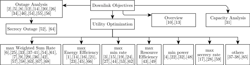
| Ref | Class | Objective | Constraints | Baselines | Method | Brief on Method |
| [1] | opt | max EE | CDPM | 2: OFDMA & NOMA | AO | 1) 2)& |
| [2] | - | outage | - | 3: MU LP, 1L-RS, 2L-HRS \RIS | - | - |
| [3] | opt | max MR | CDP o | 4: MU LP?, 1L-RS \RIS, MRT, MRT \RIS | AO | 1), 2) |
| [4] | opt | min power | AO | |||
| [5] | - | outage | - | DF-RS, NOMA | - | - |
| [6] | opt | max WSR | bQ | 1:NOMA | AO | 1) 2) , 3) Aux., 4) |
| [7] | opt | max WSR | FP | 5: SDMA , RSMA (single RIS,\RIS) | AO | 1), 2) 3) |
| [8] | - | outage | - | - | - | - |
| [9] | opt | max WSR | PU o | NOMA | AO | 1), 2) |
| [10] | - | magazine | - | TDMA, NOMA, RSMA \RIS | - | - |
| [11] | - | outage | - | NOMA, C-RSMA \RIS | - | - |
| [12] | - | outage | - | - | - | - |
| [13] | opt | review | - | - | - | - |
| [14] | opt | max EE, outage | PQ | TIN | AO | 1), 2) |
| [15] | opt | max MR | CDP | 5: RSMA , SDMA , CRS \RIS | AO | 1), 2) |
| [16] | opt | max EE | CDP | SDMA, NOMA & SCA | SSA | |
| [17] | opt | max min-SR | DPEQ* | convergence plots | AO | 1), , 2) |
| [18] | opt | max WSR | PUMw o | OMA, NOMA, decoding orders | BCD | for , 1), , 2) |
| [19] | opt | max MR | CDP o | ZF, NOMA, imperfect SIC, terrestrial RIS | AO | 1), 2) |
| [20] | - | outage | SDMA, NOMA, MRT, ZFBF | - | - | |
| [21] | opt | max EE | DPU | 3:no RIS, random and fixed RIS phases | AO | 1), 2) |
| [22] | opt | min Power | CD ME | SDMA, NOMA, AO, PSO, CS, no RIS | GA ( or AO) | outer: GA, inner: SDR |
| [23] | opt | max EE | CDPUM o | SDMA, NOMA, LPC, no-RIS | AO | 1), 2) |
| [24] | opt | max MR | CDPUM | 5: SDMA, NOMA, no-PS, single RIS | AO | 1), 2), 3), 4) |
| [25] | opt | max WSR | Uxyz o | NOMA | AO | 1), 2) |
| [26] | - | min sum-AOP | - | NOMA, no-RIS | custom | |
| [27] | opt | max MR | CDP | SDMA , NOMA , RSMA \RIS | AO | 1), , 2) |
| [28] | opt | max min-SR | PU o | MU LP , NOMA , RSMA \RIS | AO | 1), noise, 2) |
| [29] | opt | (PGS, IGS)*(no RS, RS, RS +RIS) | AO | 1), 2) | ||
| [30] | - | outage | - | NOMA, RIS-NOMA, RIS-NOMA-RS | - | - |
| [31] | - | capacity analysis | - | - | - | - |
| [32] | opt | min Power | CD o | SDMA (passive, active, no)RIS, RSMA | AO | 1), 2) |
| [33] | opt | max WSR | CDPE | SDMA, NOMA no RIS | AO | 1), 2) , |
| [34] | - | outage | b | NOMA | - | - |
| [35] | opt | max WSR | PUM: | NOMA, OMA | BCD | set decoding order, 1) 2) |
| [36] | opt | max WSR | Gjt | conventional RIS + (SDMA, RSMA) | not AO | init, schedul., group., ) |
| [37] | opt | max WSR, others | CD M* o | (IGS, PGS) (RS, TIN, \RIS), STAR-RIS | AO | 1), 2) |
| [38] | MOOP | max WSR, min | RSMA and NOMA (single and dual polarized) | FWb | - | |
| [39] | opt | max WSR | PUj | ( TP-RSMA, PP-RSMA) + RIS & a third user | AO | 1), 2) |
| [40] | ML | max utility | Learning | |||
| [41] | ML | max utility | Learning | |||
| [42] | opt | max WSR | CDP M | SDMA, passive RIS-RSMA | BCD | 1) 2) |
| [43] | opt | max RE | DPo | SDMA, NOMA, FC-RIS, group-connected RIS | AO | inner stage: 1) 2) |
| [44] | ML | Deep Learning | ||||
| [45] | ML | max EE | CDPM | MRT, split(real & imag.), SDMA | PPO & AO | 4 layer feed-forward DNN |
| [46] | - | outage | - | NOMA | - | - |
| [47] | - | outage | - | - | - | - |
| [48] | opt | min Energy | CDPUM o | Cooperative NOMA (& \RIS), NOMA, RSMA | AO | 1), , relay’s power 2) |
| [49] | opt | max EE & SE | CDP M o | random precoding, SDMA, NOMA, no RIS | joint & | DC & SCA |
| [50] | opt | max rate of user 2 | w | NOMA, \RIS, another suboptimal AO | AO | 1), 2), 3) |
| [51] | opt | max WSR | PQw* | NOMA, OMA, TS, MS, ES | AO | 0), 1):, 2), 3) |
| [52] | - | rate, secrecy outage | - | - | - | - |
| [53] | opt | max MR | CDM | HD-AF, NOMA, (Passive, no)RIS | AO | 1) 2) 2) , |
| [54] | opt | max WSR, outage | DMUxyz | IBL, FBL, NOMA, NOMA | BCD | 1), 2), 3)UAV |
| [55] | - | EE, outage | - | passive STAR-RIS, NOMA | - | EE in delay-limited mode. |
| [56] | - | outage | - | MS, ES | - | - |
| [57] | opt | max WSR | DMPo | MultiF-RIS NOMA, STAR-RIS | AO | 1), , 2) |
| [58] | opt | min MSE | P | BC (seems MU-LP), statistical CSI | AO | 1) , 2) |
| [59] | opt | max SR | DPU o | NOMA | AO | 1), , 2) , |
| [60] | ML | max WSR | w | CE, original DDPG, search, NOMA, \RIS | DRL | SAS-DDPG |
| [61] | opt | max WSR | CDPM | SDMA, NOMA | BCD | 1), 2), 3) |
| [62] | opt | max MR | CDP o | RIS, \RIS, \FD | AO | 1), 2) |
| [63] | opt | max WSR | CDPU o | conventional RIS +(NOMA, RSMA), \RIS | GBD | 1) primal, 2) relaxed master |
| [64] | - | secrecy outage | - | OMA, NOMA, \RIS | - | - |
| [65] | opt | max radar SNR | CDPUM | radar only, ISAC SDMA, (RIS, no RIS) | AO | 1), , 2), |
| [66] | opt | max EE | CDPM | SDMA, NOMA, \RIS | AO | 1), , 2) |
| [67] | ML | max WSR | CDP M* | SAC, DDPG, Genetic, MRT, ZF, NOMA | PPO-DRL | MDP & CSP |
| [68] | opt | max WSR, latency | CDPUMo | NOMA, SDMA, IFBL | AO | 1), 2), 3) |
III-B Notes on Optimization Terminology
The utility functions used by various authors (e.g. to maximize sum-rate or maximize energy efficiency) are non-convex problems. Solving these non-convex problems can be done using different methods that differ in complexity, accuracy, time, and convergence guarantees. Often surrogate functions, which are temporary (ideally convex) functions, are used to solve an approximated instance of the original problem near some initial point. Both Successive Convex Approximation (SCA) and Majorization-Minimization (MM) approaches employ surrogate functions.
The idea of SCA is to start with a feasible solution and construct an approximation to the function in a block of variables (one or more variables) that is convex and easy to solve. Then, SCA goes to the next block of variables, solve another approximate convex problem. Successive Convex Approximation (SCA)does not necessarily converge to the global optimum, but often proofs for convergence to a stationary point can be established [118].
Majorization-Minimization (MM)has two steps [119]. For a minimization problem, the first step is to find a surrogate function that always bounds the function of interest from above and intersects (or comes arbitrarily close) to the initial point. The next step is to minimize that surrogate function to get another initial point, and the cycle repeats. Constructing the surrogate function is an essential step of the algorithm. The desirable features of the surrogate function include convexity, fast convergence rate, and lower evaluation cost per iteration. More details on MM along with techniques to construct surrogate functions can be found in [120, 119].
Block Coordinate Descent (BCD)is an optimization framework where a block of variables are selected and the problem is optimized with respect to these variables. Next, another block is selected and optimized. Selection of variables affect convergence speed and can be cyclic, random, greedy, or according to other criteria [121].
III-C Capacity Analysis
The author in [31] investigates the capacity for two users: one served by the BS directly over a Rayleigh fading channel, and another user served through a reflective passive RIS. The system includes a BS, a direct user, and an indirect user. Therefore, a common message and two private messages are sent by the BS. With RSMA, and for SNR values between 27dB and 40dB, they report higher capacity for the common message over the first private message, which in turn is higher than the second private message respectively. Before the 27dB to 40dB region, the rates are fairly close to each other. Furthermore, it is shown that, a reduced capacity results in the case of imperfect CSI. The effect of varying the power splitting ratio of RSMA on the rates of the three messages is also demonstrated. The BS-to-RIS link uses Rayleigh fading. The placement of the RIS is, however, not discussed.
III-D Outage Analysis
The outage performance has been studied by many authors [2, 5, 8, 12, 14, 20, 26, 34, 46, 54, 55, 56]. In addition, the secrecy outage was also examined by articles that study Physical Layer Security (PLS) aspects [52, 64]. This classification is depicted in Fig. 14. Another classification is based on the type of the RIS, where two classes exist: reflective RIS and STAR-RIS. These two classes are examined next.
III-D1 Reflective RIS
Many articles have examined the outage performance of RSMA systems that are assisted by a reflective RIS [2, 5, 8, 14, 20, 26, 34, 46, 52, 54]. The authors in [2] analyzed the outage performance of cell-edge users using 2L-HRS and found the performance better compared to the situations of no RIS with 2L-HRS, MU-LP, and 1L-RS with RIS. Another article by mostly the same authors [5] analyzed the outage performance of cell-edge users and near users using 1L-RS and derived closed-form expressions. They also show that the proposed system outperforms RIS-assisted NOMA and DF-RS. Both articles utilize an on-off scheme to control the RIS phase shifts.
The authors in [8, 20] consider discrete RIS phase shifts. In [8], the authors derive the OP for the discrete as well as the optimal phase shifts. They observe that equal power allocation provides the best system performance. For instance, they use 4 users in the simulations, and that corresponds to a 0.2 power allocation to each stream, that is, 0.2 to the common stream and 0.2 to each of the other 4 streams. The work in [20] considers other details like asymptotic analysis as well as comparison to other multiple access techniques. It also assumes Rayleigh channels instead of Nakagami- channels, and assumes MISO instead of SISO. With RSMA, Zero-Forcing Beamforming (ZFBF) provides lower outage probability compared to Maximum Ratio Transmission (MRT). In addition, RSMA outperforms NOMA.
In [14], a C-RAN network is employed and the outage performance of two approaches for phase-shifts optimizations, namely, SCA and Semidefinite Programming (SDP), are considered. It is noted that the SDP approach has a better outage performance compared to the SCA approach. A CoMP system is considered in [34] with on-off control on the RISs. They assume some users are only served through one or more RISs because of blocked path to any access point. They discuss the selection of the RISs along with the design of signalling. They show improved outage performance of the opportunistic RIS scheme in RSMA and NOMA when some users are blocked from directly communicating with any of the access points. Comparisons of simulations and analytical expressions are also provided.
A vehicular network served by a UAV is considered in [26]. Over the flying time of the UAV, they derive the Average Outage Probability (AOP) for the vehicle while considering co-channel interference. Increasing the number of interfering vehicles significantly affects the performance. They also propose an algorithm to minimize the sum-AOP for selected vehicles. The impact of channel estimation error on the outage probability is also examined. Moreover, the RSMA power allocation coefficients are optimized for the flight time. Results show the advantage of the RIS as well as the RSMA over NOMA.
In [46], an approximate outage probability expression is derived for RSMA and NOMA after finding the Probability Density Function (PDF) of the Signal-to-Interference-Plus-Noise Ratio (SINR) for each user. The derived PDF is verified with Monte-Carlo simulations. Increasing the number of elements of the RIS or using RSMA instead of NOMA are found to provide better performance. In addition, they show better outage performance for RSMA when the SNR is relatively high, and a similar trend when the number of RIS elements are increased for fixed transmit power. Moreover, they show that increasing the RIS elements can compensate for small CSI imperfection.
The authors in [54] examine the outage probability, among other performance measures, for a system with a relay and an RIS mounted on a UAV. Finite Block-Length (FBL) and Infinite Block-Length (IBL) in addition to imperfect SIC at the users as well as Residual-Self Interference (RSI) at the UAV are considered. SIC errors are found to negatively affect the outage performance at the users. In addition, the DF relaying link is better than the RIS link for low transmission power. BLock Error Rate (BLER) expressions are also derived in [54].
In [52], the covert communication rate and DEP are evaluated in a system of three users and a single transmitter. RS is conducted at the BS to serve two Legitimate Users (LUs). Moreover, an approximate expression for the Secrecy Outage Probability (SOP) is derived, and the asymptotic SOP is analyzed. Comparisons of simulation and analytical results are provided, with a small gap because they approximated the channel distribution by a gamma distribution. The use of RIS is found to lower the DEP for the covert user, as well as increase the secrecy rate. The DEP shows a convex behaviour for increasing total transmission power, and an optimal transmission power should be used to get the lowest DEP. When the total power is low, the probability of mis-detection is the dominant term and it decreases with increasing power, resulting in a decrease of DEP. Then, the probability of false alarm becomes the dominant term and increases with increased total power, which results in an increase in DEP again.
III-D2 STAR-RIS
Several works have considered a STAR-RIS for the outage analysis [12, 55, 56, 64]. In [12], the authors consider the ES and MS modes with continuous phase for their analysis where two users are served by each STAR-RIS. They also consider that Rician fading are spatially correlated due to the proximity of cells of the STAR-RIS. They derive the outage probability for the IBL transmission. In addition, they derive the BLER and goodput for the FBL system. Capacity analysis and asymptotic outage probability are also presented. Conclusions include a preference for alternating elements in the MS mode. Furthermore, the outage probability follows a convex-like shape, depending on whether the private message or the common message are in outage. The invalid SINR thresholds for the common message are highlighted.
An active STAR-RIS is considered in [55] with perfect and imperfect SIC. They derive the outage expressions for users and find the diversity order. The diversity order is zero with imperfect SIC due to residual interference, and it is related to the number of elements of the STAR-RIS when the SIC is perfect. In [55], the EE of the system with active STAR-RIS is compared to that with passive STAR-RIS in the delay-limited mode. The system throughput for a fixed data rate can be related to the outage probability in that delay-limited mode. They report that, despite the extra power requirement of the active STAR-RIS, it can still achieve overall better EE for the system.
In [56], the users are assumed to be distributed according to a Poisson point process (PPP), and stochastic geometry is utilized to study the outage probability of users in the transmit zone as well as the reflect zone of the STAR-RIS. Closed-form expressions are found for the outage probability in terms of the Meijer G-functions. Increasing the density of the devices, the RS power coefficient, or the number of elements in the RIS are all found to improve the outage probability.
The authors in [64] study the system secrecy performance. They find a closed-form expression for the SOP with Nakagami- fading. Moreover, the asymptotic performance at high SNR is also studied. The effects of the number of elements of the surface, transmit power, and target secrecy rate on the system are examined. In addition, comparisons to NOMA, OMA, and no RIS cases are provided. The choice of the power allocation factor is found to be a critical parameter. If it is too low or too high, the SOP is high. Only for moderate values is the SOP low. Ideally, the optimum value should be chosen which results in the lowest SOP.
III-E Problem Formulations
For the downlink system with 1L-RS, assume that the BS is sending a message to the th user. The BS splits each message into a private part and a common part , as depicted earlier in Fig. 3. Hence, there is a total of messages. The BS then combines all common messages into a single common message . Hence, the total number of messages is reduced to . The single common message is encoded into a common stream , and each private message is encoded into a private stream . Subsequently, all messages are superimposed in the power domain by the precoder to form the transmitted signal
| (7) |
where is the precoding vector applied to the common message, and is the precoder vector applied to the private message. Note that . In other words, all antennas are used to transmits all messages. Furthermore, a common assumption is to assume that the symbols are uncorrelated, that is . In addition, the power is limited by the power budget
In each time slot of a discrete-time system, the received signal at the th user is
| (8) |
Here the received signal is based on the model ‘(c) BS-RIS-DorS’, where each user gets a direct link and a reflected link through the RIS. The direct link is represented by , and the reflected link is represented by , where is the channel from the BS to the RIS, is the matrix of phase shifts introduced by the RIS, is the channel from the RIS to the th user. In addition, is the additive noise at the th user.
Other formulations follow in a similar way. Then, relevant conditions are imposed based on the objectives and assumptions in each paper. For instance, the phase shift matrix of the RIS can be assumed to be diagonal, block diagonal, or full. In addition, the structure of depends on the assumption of the array type, e.g. a ULA or a UPA. The next step is to optimize some utility based on a specific model. This section discusses multiple optimization objectives that exist in the reviewed literature. A classification of the articles based on the optimization objective can be found in Fig. 14. In addition, the same information can be found in the ‘Objectives’ column of Table IV. In particular, seven subsections are now presented: Weighted Sum-Rate (WSR)maximization, Energy Efficiency (EE)maximization, Minimum Rate (MR)maximization, Resource Efficiency (RE)maximization, transmit power minimization, Secrecy Rate (SR)maximization, as well as other optimization objectives.
III-E1 Maximize Weighted Sum-Rate
The Weighted Sum-Rate (WSR)maximization problem is the most widely studied objective [6, 25, 33, 37, 38, 39, 54, 61, 7, 9, 29, 36, 42, 57, 63, 67, 68]. In [25], a UAV carries an RIS and a relay. Three modes are considered, RIS mode, relay mode, and hybrid mode. For the RIS mode, they use AO to optimize the UAV position and the RIS phase shifts. The former is done through a one-dimensional search, and the latter through a modified Riemannian Conjugate Gradient (RCG) method. The authors investigate the effect of SIC errors and show an advantage of RSMA over NOMA by a maximum of 16%. They also conclude that the hybrid mode of the UAV is better than either the RIS or the DF relay alone. The same authors provide a more detailed study in [54] where they consider Block Coordinate Descent (BCD) method to decompose the problem into three blocks: power allocation, phase shift optimization, and UAV position optimization. The other variables are fixed in each block. Power allocation follows a heuristic approach, while phase shifts optimization follows a method based on RCG. IBL and FBL are also considered. Since selection combining is used, the hybrid mode is found to surpass either the relay or the RIS modes with IBL or FBL in terms of WSR. Nevertheless, for large number of RIS elements, the RIS-aided mode provides similar or better performance to the relay-aided mode. The effect of imperfect SIC on reducing the achievable WSR is also examined.
The authors in [61] use a Sample Average Approximation (SAA) and Weighted Minimum Mean Square Error (WMMSE) methods to obtain the average rate which they relate to the long-term Weighted Ergodic Sum Rate (WESR). Then a BCD method is used to solve the resulting problem which is convex in one variable if others are fixed. Specifically, the algorithm alternates between the transmit power, the RIS phase shifts, and the common rates of users. The algorithm has a finite lower bound, and thus is guaranteed to converge. Simulation results show convergence within 10 iterations. In addition, considering inaccurate estimation of CSI, they show a consistent advantage of RSMA over NOMA and SDMA.
A multi-antenna system is considered in [58], where the users have more than one antenna. They utilize MMSE for precoder design and use Projected Gradient Ascent Method (PGAM) for RIS phase shift optimization. Furthermore, they study the perfect and statistical CSI scenarios. A maximum sum-rate deterioration of 34% was observed with imperfect CSI. Furthermore, using 4 or 6 antennas at the users are recommended due to reduced complexity, while using 8 antennas reduces the sum rate due to interference among the antennas.
The authors in [40] and the later journal article [41] consider maximizing the rate of video streaming. Specifically, they consider that multiple users are requesting tiles of a 360-degree video stream. Different users can request different tiles of the video. The bitrate of these tiles, the RS power allocation coefficients, RIS phase shifts, and beamforming vectors are jointly optimized. They exploit Deep Deterministic Policy Gradient (DDPG), actor-critic, and imitation learning to propose the ‘Deep-GRAIL algorithm’. They also propose a Deep Neural Network (DNN) module for policy learning in their algorithm, which includes a Differentiable Convex Optimzation (DCO) layer. The report better performance of their algorithm compared to the cases of no RS, RS with AO algorithm, as well as RS-Non-Orthogonal Unicast and Multicast (NOUM) with AO. They also compare to an algorithm that uses Supervised Learning (SL) to train the DNN module. Despite the superiority of their algorithm, the RIS-aided RSMA system with AO can attain performance ‘close-enough’ to that of their proposed algorithm, surpassing the other SL benchmark approach as well.
A less popular way of solving the optimization problem of DL MU-MISO system with RSMA and STAR-RIS is to utilize the fairly recent PPO family of DRL [67]. By properly designing the reward function, state space, and action space, a PPO-based algorithm was shown not only to have good convergence behaviour, but also enhance the sum rate compared to Soft Actor-Critic (SAC), DDPG, Genetic Algorithm (GA), MRT, ZF, and the random solution; for any maximum available power between 1W and 30W [67]. Moreover, after studying the learning rates of all the 36 combinations of users, elements, and , the authors show that increasing the available power causes a slow improvement in the training reward which is attributed to the simultaneous increase in interference [67]. Although the convergence behaviour is consistent among all these scenarios, it is interesting to note that the case with users generally gets higher reward for a low number of training episodes. Then the case of users surpasses the former case anywhere between 6000 and 8000 training episodes.
In [68], they aim to maximize the throughput for a specified PEP. The study is primarily an extension of [23] to consider multiple RISs. The authors propose a three-stage AO algorithm to optimize beamforming, block-length, and RIS phase shifts. In addition, another optimization formulation is presented to minimize the maximum block length. This formulation is an extension to the main formulation and is targeted at minimizing the worst-case latency while maintaining the rate and power requirements. The impact of channel estimation errors is also studied. Using a few RISs with low number of elements is better than a single RIS with large number of elements due to the additional paths. Moreover, relaxing the PEP requirement enhances the rate and it gets closer to the Infinite Block Length (IFBL) case. In other words, reliability can be traded for throughput. Furthermore, RSMA with FBL can achieve rates similar to those of NOMA and SDMA with IFBL.
The authors of [39] consider the overloaded system and show that the same sum-rate can be achieved at 5dB-less (depending on the number of RIS elements) when the RIS-assisted RSMA system is used compared to RSMA alone. They include comparisons of the TP-RSMA and PP-RSMA for the two groups of users in their system model. One group is served by OMA while the other is served by RSMA.
III-E2 Maximize Energy Efficiency
The Energy Efficiency (EE)maximization problem is similar to the WSR maximization problem, but with a term in the denominator that accounts for the power consumption. Several works studied this objective [1, 14, 16, 21, 23, 45, 66]. The authors in [1] aim to maximize the EE under a minimum rate constraint. They employ AO to solve the subproblems of beamforming and RIS phase shifts’ optimizations, and the subproblems are solved using SCA. The authors show that RSMA provides a higher EE compared to OFDMA or NOMA. However, the difference of performance between NOMA and RSMA is not huge (up to 12%). Three BSs, three RISs with elements each, and three users are used in their simulation study.
The C-RAN network is considered in [14]. The authors note that they aim to dynamically allocate user clusters and sets of common messages. Static sets are assumed for the latter in [1] which do not fully exploit the integration of the RIS and RSMA [14]. In the EE maximization in [14], they consider the fronthaul capacity and power constraints of each RRU, which clusters of RRUs serve which users, passive RIS phase shifts, as well as QoS constraints for users. An AO algorithm is employed to solve the problem.
In [16], a THz model is considered; the RIS is assumed to be a UPA and its phase shifts are uniformly quantized. They utilize Salp Swarm Algorithm (SSA) algorithm and show that it provides a better EE in less time compared to a SCA algorithm. The results generally show an advantage for RSMA over SDMA or NOMA, but not in all cases.
An AO algorithm is presented in [21] for the EE maximization, and it shows better performance compared to their benchmarks. Fractional programming is first employed to get rid of the power terms in the denominator. They compare the performance to the benchmark cases of no RIS, random RIS phases, and fixed RIS phases. When increasing the number of RIS elements, the EE first increases and then decreases. Hence, increasing the number of RIS elements does not always increase the EE. Moreover, the EE of the system is the lowest when the RIS is not close to either the transmitter or receivers. Furthermore, the EE increases logarithmically for increasing power in decibels.
In [23], the objective is to maximize the EE with Far-Users (FUs)only reachable via the RIS, while ensuring that the rates satisfy a given error probability. They proceed with an AO algorithm for both SPC and LPC settings. The algorithm performs better than random phase shifts, and also validate the convergence. Next, they show that RIS-aided RSMA SPC not only outperforms its NOMA and SDMA counterparts in terms of EE, but also can surpass RIS-aided NOMA LPC for packet sizes above 1500 bits, as well as surpass RIS-aided SDMA LPC for packet sizes above 2500 bits. This implies that very short packet length are less energy efficient compared to LPC, which is true for all of SDMA, NOMA, and RSMA. They also illustrate the benefit of the passive beamforming at the RIS to enhance the gain for both NUs and FUs.
A PPO-based DRL method is the main focus of [45] in a SWIPT network. It is a non-alternating algorithm, that is, it does not alternate between phase shift and beamforming optimizations. In the optimization, they consider discrete phase shifts, the non-linear EH model, power budget, and QoS constraints for information and energy transfer. The beamforming vectors, RIS phase shifts, common rates of RSMA, and PS ratios at the receivers are jointly optimized. They also present another solution based on SCA as a benchmark, where the constraint on discrete phase shifts is relaxed. RSMA is found to enhance the EE of the system. In addition, the PPO-based approach only loses small EE in exchange of large time savings. This can be very important to quickly arrive at the near-optimum result in time-varying channels. For the RIS position, they show that it is not always best to keep the RIS near the transmitter or the receiver, rather, in a specific case it is optimal to keep the RIS in the middle.
A multi-cell system is considered in [66] where they focus on enhancing the performance of cell-edge users. An AO framework is utilized where an SCA method is employed for beamforming optimization and Semidefinite Relaxation (SDR) along with a penalty function are used for phase shifts optimization. Increasing the minimum rate demand is found to reduce the EE. In addition, increasing the transmit power reaches a saturation point where further increase does not result in additional EE. Moreover, the EE increases when the number of elements in the RIS increase. Nonetheless, it seems that further increase would result in reduction in the EE as observed by [21].
III-E3 Maximize Minimum Rate
Minimum Rate (MR) maximization is another optimization objective that aims to maximize the rate of the user having the lowest rate. This objective embeds some fairness in the main objective. It can also be coupled with other constraints like minimum energy. A few works have considered this objective [3, 15, 19, 24, 27, 44, 53, 62].
In [3], the authors study minimum rate maximization and consider discrete RIS phase shifts. They avoid the traditional SCA algorithm to avoid the challenging task of finding the initial feasible point, and use a penalized SCA which can start form an arbitrary point. Comparison with NOMA is not provided, but other benchmarks are used which show the advantage of their algorithm.
The authors in [24] propose an AO algorithm for the double-RIS system. As baselines, they compare to SDMA and NOMA and single RIS, and they show that using double-RIS achieves better max-min rate compared to all previous baselines. The optimization consists of 4 subproblems:
-
1.
Optimization of precoders and the common rate given the PS ratio and the RIS matrices and which is done through SDR and SCA.
-
2.
Optimization of PS ratio given the precoders, common rates, and RIS matrices, via a closed-form solution.
-
3.
Optimization of the phases of the first RIS utilizing SDR and SCA.
-
4.
Optimization of the phases of the second RIS utilizing SDR and SCA.
The authors explain that iterations are non-decreasing and capped by the maximum available power which guarantees convergence.
The authors of [44] utilize the achievable rate of the worst User Equipment (UE) as the loss function in the end-to-end training of their proposed Deep unFolding Active Precoding Network (DFAPN) and RIS Reflecting Network (RRN). Their DFAPN is model-driven, and is utilized to get key parameters in the iteration of their Approximate Weighted Minimum Mean Square Error (AWMMSE) precoding scheme. The RRN is utilized to design a frequency-flat RIS matrix despite the frequency-selective channel. The RRN is based on the emerging transformer structure, and it extracts the correlation features of the OFDM channel. Furthermore, the emerging transformer structure is also utilized for CSI acquisition. Correlation features are also extracted from the multiple subcarriers of CSI to reduce feedback and pilot overhead.
III-E4 Maximize Resource Efficiency
The main objective of this Resource Efficiency (RE) maximization formulation is to consider the tradeoff between EE and SE. This formulation is used in [43]. Furthermore, a similar formulation that considers both EE and SE is proposed in [49] where a multi-objective problem is formulated. In this paper, we expand the meaning of RE to also include the formulation of [49] under one header. In [43], the objective function is a weighted linear combination of the EE and the SE. Their algorithm has two-stages. The problem is prepared and simplified in the first stage and a closed-form solution is found. Next the second stage carries out the AO over the beamforming and the phase shifts and gains of the active RIS. In addition, they extend the optimization to the 2L-RS scheme. The gains and phase shifts of the RIS are considered to be quantized. In the simulation study, different schemes are compared including NOMA, SDMA, FD-RIS, group-connected RIS, as well as passive RIS. They also show that the performance of the quantized scheme is close to that of the continuous scheme.
The authors in [49] propose a joint optimization scheme for the non-convex fractional problem of optimizing EE and SE with RSMA and other constraints like QoS guarantees for PUs; based on Difference-of-Convex (DC) and SCA techniques. They show a consistent advantage of their scheme over NOMA, SDMA, random and constant precoding. The performance of NOMA is sometimes close to their proposed scheme. What is interesting is that using random or consistent precoding offers an advantage over the case without the RIS surface. They also show the trade-off between EE and SE where the proposed scheme maintains better EE for values of SE between 10 and 20 bps/Hz compared to other schemes.
III-E5 Minimize Transmit Power
Instead of maximizing the SE, EE or MR, the formulation could address the transmit power directly. Four articles consider this formulation [4, 22, 32, 48]. The authors in [4] minimize the transmit power under QoS constraints and find that the use of RS with RIS yields more power savings than the individual power savings by each technique.
A SWIPT system is examined by [22] where they aim to reduce the transmission power subject to EH and rate constraints. They decompose the non-convex problem into a bi-level problem. The outer level is solved with GA and the inner level is solved via SDR with a penalty method. In addition, an AO algorithm is implemented to show its inferior performance and extra complexity compared to the GA-based algorithm. SDMA and NOMA are considered for comparison in perfect and imperfect CSI. It is observed that as the EH requirements increase, the gain of RSMA over SDMA increases. Moreover, the RIS-aided RSMA system is found to achieve the lowest power consumption compared to the SDMA or NOMA systems. Furthermore, RIS-assisted NOMA system becomes impractical as the rate requirements increase, because NOMA requires multiple layers of SIC, which in turn requires the BS to use more power.
An active RIS is considered in [32] for URLLC transmission. They aim to minimize the power consumption at the BS as well as the active RIS. An AO algorithm is presented where the RSMA optimization employs Taylor approximation, fractional programming, and SCA. Moreover the RIS optimization employs the big-M formulation, DC, and fractional programming. Overall, the authors found that the active RIS-assisted system consumes less power and requires less number of elements compared to its passive counterpart. In addition, the RSMA system consumes less power compared to the SDMA system.
A cooperative system is considered in [48] where the near user re-transmits the common message to the far user. This introduces two additional design parameters compared to the common formulation: the time split ratio, and the transmission power by the near user. In addition, the first and second time slots could have different phase shifts at the RIS. The objective is to minimize the transmit power of the BS in addition to minimizing that of the near user. The authors focus on two users and show lower energy consumption of the RIS-assisted cooperative-RSMA compared to cooperative-NOMA (with and without RIS), regular RIS-assisted 1L-RSMA, RIS-assisted NOMA and cooperative-RSMA without RIS.
III-E6 Maximize Secrecy Rate
Three papers consider this objectives where the secrecy rate is to be maximized [17, 28, 59]. In [17, 28], the objective is to maximize the minimum secrecy rate, and in [59], it is maximizing the rate of the covert user. Furthermore, in [28], AO is used, where in the first alternation, the BS’s beamformers are optimized (along with the noise that is assumed unknown). The noise here refers to the exploitation of the common message to create artificial noise at the eavesdropper. In the other alternation, the RIS phase shifts are optimized. They also show that the proposed RIS-assisted RSMA system attains the same or higher Max-Min Fairness (MMF) multiplexing gain compared to both NOMA and MU-LP.
III-E7 Other Optimization Objectives
This category includes three papers as depicted in Fig. 14, namely [37, 38, 65]. The authors in [37] proposed a general framework that considers different objectives including EE or WSR maximization. Although the authors focus on a downlink system, the framework can be extended to other scenarios. They consider realistic assumptions like devices suffering from I/Q Imbalance (IQI), and they employ Improper Gaussian Signaling (IGS) as an additional interference management technique along with RS. In addition, they consider the reflective RIS and also present an extension to the STAR-RIS. An AO formulation is presented where the precoder optimization is done through MM and they utilize lower bound surrogate functions for the RIS optimization where three feasibility sets are considered. They compare the performance with Proper Gaussian Signaling (PGS), Treating Interference as Noise (TIN), and the case without RIS. They show the advantage of RS with IGS in improving the EE and SE of the overloaded DL system.
The authors in [38] follow a non-traditional approach where they utilize a modified variant of RSMA that encodes the common stream in a polarization orthogonal to that of the private streams. The benefit is that the users can decode the private symbols without SIC. However, since the channel can cause cross-polar interference, the authors develop a Multi-Objective Optimization Problem (MOOP) and solve it using a Frank-Wolfe (FW)-based method. The precoding design is explained with three main matrices. The first two are for cancelling the inter-group interference and directing the group transmission to the intended group, while the third is for reducing intra-group interference. Next the optimization of the dual-polarized RIS is presented through a FW-based method.
The RIS-assisted RSMA ISAC system is considered in [65], where the authors aim to maximize the radar SNR. Typical constraints for 1L-RS are considered, namely, decodable non-negative common rate and a QoS constraint, where each user is guaranteed a total rate above some threshold. In addition, power limitation at the BS is considered in addition to unit-norm constraint on the RIS’s phase shifts matrix. An AO framework is presented which utilize MM and DC approximation. The authors show that the RSMA ISAC system almost matches the performance of the radar-only system regardless of the use of the RIS. Of course, the RIS provides an independent gain in both systems, and that gain is linear with increasing number of RIS elements. This is in contrast to the SDMA ISAC system, which achieves lower radar SNR.
Multiple optimization objectives have been studied in the literature as presented in this section. The objectives include WSR maximization, EE maximization, MR maximization, RE maximization, SR maximization, and transmit power minimization. The next subsection provides an example of WSR maximization, followed by a subsection that draws a few lessons to conclude this downlink section, then the next section (Section IV) provides an overview of works studying uplink channel models.
III-F Example of Weighted Sum-Rate Maximization
The previous section described multiple optimization objectives including WSR maximization, EE maximization, transmit power minimization, etc. This section provides an example of WSR maximization for an RIS-assisted RSMA downlink MISO system that employs 1L-RS. A common type of RS, known as 1L-RS will be explored in this section, along with comparisons to SDMA and NOMA. In addition, two benchmarks are briefly explained, namely, Dirty Paper Coding (DPC)and MU-LP. In Fig. 15 and Fig. 16, we provide sample performance results for the optimization algorithms when perfect CSIT is assumed and model ‘b) BS-RIS-D&S’ is adopted. The model is very similar to that of [122] but with two users to draw the rate region in Fig. 16. We utilize a nested alternating optimization formulation to solve the resource allocation problem. In particular, the RIS phase shifts optimization is almost the same as presented in [122], while the MU-LP and 1L-RS follow the transformation of the sum-rate maximization problem into an equivalent WMMSE minimization problem as described in [107] and [73] respectively. A modification of the codes published in [122] and [123] is utilized in these simulations. The simulation parameters are listed in Table V. Fig. 15 shows two sets of traces, the upper set corresponds to the nested AO, while the lower set is without RIS optimizations. In particular, the lower set shows the cases of random RIS phase shifts and the case of no RIS. It is evident that the RIS can provide a decent gain. In addition, since perfect CSIT is assumed, MU-LP is already providing a very good performance.
| Parameter | Value |
|---|---|
| Number of BSs, | |
| Antennas per BSs, | |
| Location of the BSs | |
| Number of RISs, | |
| RISs elements , | |
| Location of the RISs | |
| Number of users , | |
| Antennas per user , | |
| Location of user 1 | |
| Location of user 2 | |
| BSs-RISs channel | Rician |
| RISs-user channel | Rician |
| BSs-user channel | Rayleigh |
| Rician Factor , | 10 |
| Random Channels | 100 |
| LoS Path Loss , | |
| NLoS Path Loss , | |
| Noise | |
| Bandwidth, | kHz |
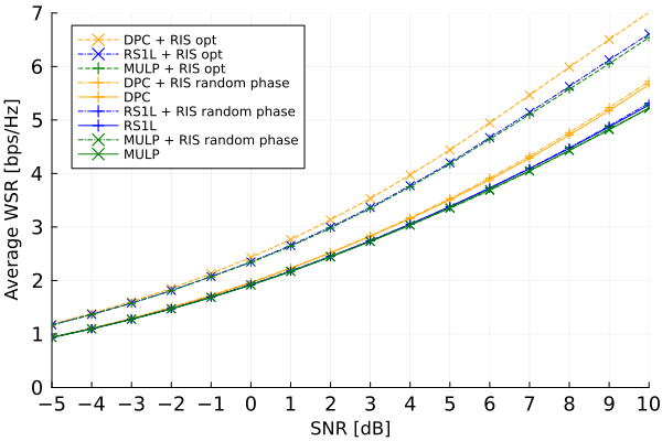
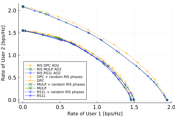
III-F1 Dirty Paper Coding
In a MU-MIMO system, when the CSI is known at the transmitter, DPC achieves the capacity region of the MIMO-BC channel [79, 80]. Nevertheless, implementing DPC is computationally complex and not practical. As such, it can be considered as a benchmark for other multiple access schemes in MU networks. This section briefly describes the procedure of precoder optimization with DPC [124]. Users are encoded sequentially in DPC ensuring that the latter users are not interfered by the previous users. Hence, all possible permutations of the users should be considered, and the rate region is the union of all rate regions with each permutation. The rate region of the BC channel can be characterized through characterization of the dual MAC channel. Building on top of (1), the dual MAC channel for the th user is . Let denote the transmit covariance matrix of the th user, and denote the power budget of the th user Assuming the user weights vector is sorted from largest to lowest weight, the WSR can be expressed as [124]
| WSR | (9) | |||
| (10) |
where
| (11) |
and the derivative with respect to the th covariance matrix is
| (12) |
To simplify the expression, with an abuse of the notations, we assume that . The algorithm in [124] updates the ’s iteratively. In the next two equations, the left-hand side represents the value at the new iteration:
| (13) | ||||
| (14) |
where , is the principal eigenvalue of the gradient , and is the corresponding principal eigen vector. In addition, is found by the line search:
| (15) |
III-F2 Multi User Linear Precoding
The objective of this formulation is to maximize the WSR in (17). The achievable rate for the th user is
| (16) |
assuming Gaussian signalling. With the user weights vector and power budget , the WSR maximization problem can be written as
| (17) | ||||
| (18) |
The constrained problem in (17) can be solved by introducing two auxiliary variables and to relate a WMMSE minimization problem to this WSR maximization problem. Note that these two matrices can be used directly to solve the WSR maximization problem in the following alternating fashion:
| (19) |
That is, once the first is initialized, and can be found by equations (20) and (23), respectively. After that, a new can be found using equation (24). The algorithm stops when the relative rate error among the last two iterations is small, say . The WMMSE matrices and are detailed in [107]. The expressions for , , and are now listed. The MMSE receive filter is
| (20) |
and the MMSE matrix is
| (21) |
where the noise covariance matrix is
| (22) |
Furthermore, the MMSE weight matrix is
| (23) |
Finally, defining , , , the precoder can be found by
| (24) |
where
| (25) |
is a gain scaling factor and
| (26) |
III-F3 1-Layer Rate Splitting
With RS, just like MU-LP, we utilize the conversion of the sum-rate maximization problem into an equivalent WMMSE problem [73]. Note that a globally-optimum algorithm for a 2-user RS MISO-BC was proposed [125], but the difference to the WMMSE formulation was reported to be small. Compared to the MU-LP WSR maximization problem in (17), the optimization formulation gets two new conditions. The first is that the sum of the allocated common rates must not exceed the achievable common rate at the worst user, that is
| (27) |
where , and is the common rate allocated to user . The second condition is
| (28) |
which may be dropped if the algorithm is guaranteed to be restricted to non-negative values. The optimization can also be solved in an alternating fashion after relating the WSR maximization problem to a WMMSE minimization problem as described in [73].
III-G Lessons Learned
The following points summarize the lessons learned for downlink resource allocation in RIS-aided RSMA systems.
-
•
When the common message is in outage, both messages are in outage. But the converse is not true. This leads to convex-like shape of the outage probability for both the transmit user and the reflect user in the STAR-RIS-aided system, where there is an optimum value of the common rate split ratio [12, 8, 20].
-
•
A similar convex-like shape is also observed for the secrecy outage probability in [64] because either of the legitimate users will be negatively affected at very high or very low values of the common rate splitting ratio.
- •
-
•
Using RIS with quantized bits in the RSMA system is more energy efficient even though the SE is slightly reduced due to quantization [43].
-
•
The use of double-RIS (in cascade) can achieve better max-min rate compared to SDMA, NOMA, and a single RIS with RSMA. [24]
-
•
The EE increases with increasing number of RIS elements up to a certain point. After that, further increase in the number of RIS elements results in a decrease of the EE [21].
-
•
The EE is the lowest when the RIS is in the middle between the transmitter and users, i.e. when the RIS is not close to either of them.
-
•
In downlink RIS-assisted Half-Duplex (HD) RSMA system with two users, if the user with the better channel cooperates to deliver the common stream to the other user with less-favourable channel conditions, the overall energy consumption of the system will be lower compared to traditional RIS-assisted 1L-RSMA, RIS-assisted cooperative-NOMA, as well as HD RSMA without RIS. [48]
-
•
In a downlink system with a single transmit antenna with transmissive RIS (TRIS) of sub-arrays, the performance is similar to that of a conventional -antenna system but at a cheaper cost and reduced complexity. RSMA consistently outperforms NOMA and SDMA in such a system [61].
-
•
RSMA with FBL can achieve rates similar to those of NOMA and SDMA with IFBL [68].
-
•
SPC can benefit from RIS-assisted RSMA networks compared to those with NOMA and SDMA in terms of EE. In fact, RIS-assisted RSMA SPC can surpass NOMA and SDMA LPC for some packet sizes [23].
-
•
The ISAC system can benefit from RSMA where both communications and sensing can be done simultaneously and achieve a radar SNR similar to that achievable by the radar alone, as illustrated in [65]. Furthermore, the RIS provides an extra independent gain.
-
•
An active RIS could achieve a lower overall system power consumption and require less number of elements compared to its passive counterpart [32].
-
•
The use of an active STAR-RIS may be more energy efficient for the full system [55]. Despite the fact that the active STAR-RIS consumes more power than its passive counterpart.
-
•
Increasing the number of STAR-RIS elements, or the RS power splitting factor, or the density of users are all found to reduce the outage probability [56].
-
•
For a system with two legitimate users and an eavesdropper (or warden), the detection error probability first decreases then increases as the total transmit power is increased at the transmitter. This can be attributed to the initial decrease of the probability of missed detection, followed by the increase of the probability of false alarm [52].
- •
- •
-
•
In an RSMA system with a dedicated RIS to each cell-edge user, ZFBF is found to outperform MRT [20].
-
•
In SWIPT systems, using RSMA is a good idea to deliver power to the Internet of Things (IoT) devices, since the common stream is delivered to all devices. In addition, the RIS can establish a virtual LoS link between the transmitter and the device. Improved EE in RIS-assisted RSMA SWIPT systems has been reported [45].
-
•
In a SWIPT system with EH and rate requirements, increasing the rate requirements renders the RIS-assisted NOMA system impractical compared to the SDMA and RSMA counterparts in terms of transmission power [22]. The reason is that NOMA requires multiple layers of SIC which require more transmission power from the BS.
-
•
The RIS-assisted RSMA system maintains the best performance in underloaded and overloaded scenarios when SR maximization is considered [28].
IV Uplink Resource Allocation
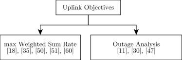
A few papers [11, 18, 30, 35, 47, 50, 51, 60] considered the uplink channel models. These papers are included in all tables in this document. Details of the models were presented earlier in Fig. 13. For Table IV, the abbreviations for the ‘Constraints’ column follow the same definitions as presented at the beginning of Section III. Fig. 17 shows a classification of the objectives of the uplink papers. In this section, an overview of these uplink articles is presented. Then, some open challenges are discussed in the next section.
IV-A Maximize Weighted Sum-Rate
Five articles considered WSR maximization in the uplink setting [18, 35, 50, 51, 60]. A group of four authors focused on the uplink system in three papers [18, 35, 51]. A mmWave model is considered in [18], where RSMA was shown to provide up to 40% higher sum-rate compared to NOMA, and up to 80% compared to OMA. To reduce interference among users, they consider clusters of users where RSMA is only used within the cluster. Clusters with higher user density are allocated larger bandwidth to ensure fairness. In addition, a multi-layer RS model is assumed, where each user can split its message into multiple streams. In [35], clustering is not considered, but they derive a near-optimal decoding order. The authors note that the ascending order of the users’ split proportions, as well as the descending order of channel conditions can be used to form a decoding order that attains better sum-rate. A multi-layer RS was considered in [51], that is, each user can split its message into more than two parts. Then, the decoding order is decided as the first step in the optimization process.
In [50], two users are assumed and only one of them does RS while the other does not. This is because, for users, only streams are needed to achieve the capacity of the MAC channel [72]. The objective is to maximize the rate of the second user which does RS, while maintaining a minimum rate for the first user. Note that this objective can still be considered a WSR maximization since the rate of user 1 is a constraint. In addition, the rate of the first user is optimized first to get the initial values of beamforming and RIS phase shifts. The optimization is carried out using AO in three steps to allocate the power at the transmitter, the beamforming at the receiver, and the phase shifts of the RIS. The authors show that the RIS-assisted RSMA system achieves a better rate compared to other schemes with NOMA, without RIS, or with a suboptimal AO approach. However, the performance of the second best case, the RIS-assisted NOMA system, closes the gap and approaches the performance of RIS-assisted RSMA system as the number of antennas at the BS or the number of elements at the RIS is increased. In [60], each user splits its message into two streams, and they propose a DDPG approach to jointly optimize the beamforming, power allocation, and RIS phase shifts to achieve higher sum rate. The problem is formulated as a Markov decision process, and they also propose a Safe Action Shaping (SAS) process for constraint violations. An important justification for using DDPG is that they consider a time-varying channel due to user mobility, instead of the common quasi-static channel model. The DDPG is used to learn the CSI in real time and maximize the sum rate in the long term. Another justification is that, traditional optimization algorithms do not scale well as the number of RIS elements increase. It was observed that the sum rate increases linearly with using the proposed DDPG algorithm. They compare performance with a Cross Entropy (CE)-based scheme, a PPO-based scheme, and a local search scheme over quantized RIS phase shifts.
IV-B Outage Analysis
A cognitive-RSMA system is explored in [11, 30, 47] where an RIS is used to facilitate the uplink transmission of the Secondary User (SU). An important objective is to maintain the QoS of the PU, thus, no interference should be introduced by the SU. For that, an interference threshold sent by the BS is assumed, and three cases are detailed in [11] based on that interference threshold. An OP expression is derived for the SU for each of the three cases. Through simulations, the authors show that this system has better outage performance compared to a NOMA-based system, as well as a cognitive RSMA system without RIS. A similar journal article also focuses on cognitive-RSMA [47] where only one user (the SU) does RS, and a continuous range of RIS phase shifts is considered. The authors derive the outage probability for the SU. Furthermore, it is noted that considering more than two users as well as discrete RIS phase shifts are possible future directions. A quite similar article to the previous two (i.e. [11, 47]) is [30]. Similar articles without an RIS appeared earlier [127, 128].
IV-C Lessons Learned
The following summarizes the lessons learned for uplink RIS-aided RSMA systems.
-
•
The sum rates increase linearly with for an uplink system with the DDPG algorithm proposed in [60].
-
•
For a 2 user uplink system where a single user does RS, the RIS-assisted NOMA system is generally the second best after the RIS-assisted RSMA system, and the gap between them diminishes as the number of RIS elements or the BS antennas are increased.
- •
V Open Challenges and Research Directions
This section briefly discusses some directions for future research and highlights some challenges. In particular, it discusses modelling the RIS, the number of receive antennas, Integrated Sensing And Communication (ISAC), Holographic MIMO, and SIC-free decoding.
V-A RIS models
Increasing the number of elements in the RIS is expected to increase performance, e.g. the SNR. Nevertheless, larger surfaces require revised and detailed models to capture physical phenomena properly, which allows better optimization for the required objective. Simple RIS models may not be physically consistent. In addition, they may overlook some characteristics that can be exploited by the multiple access technique. More examination of Two Dimentional (2D) RISs [129] models is expected, as they may provide a better chance of redirecting or refracting the incident beam into the desired direction. The next paragraphs highlights mutual coupling, and nonlinearity of the RIS.
Mutual Coupling is a natural phenomenon that can occur in mechanical or electrical systems such as antenna arrays. When the elements of the RIS are extremely close to each other on the sub-wavelength level, the response of an element cannot be unaffected by the response of its neighbours.
Frequency modulation through the RIS surface remains an open direction, compared to the majority of studies that explore amplitude and phase modulation. For instance, an incident signal at with a frequency can leave the surface at with a different frequency [129].
Channel estimation needs to be addressed in a way that does not require the use of two coherence blocks, as in [9] where the same common message is sent twice in two coherence blocks in the Opportunistic Rate Splitting (ORS) scheme.
Furthermore, traditionally, the RIS is assumed to have a linear operation, whereas in practice it may not always behave linearly. Nonlinearity can be leveraged to modulate the incident signal before reflecting it [130]. The effect of the RIS’s nonlinearity on the performance of the communications system based on multiple access techniques like RSMA remains to be explored. This can be useful, for instance, in the uplink, where the BS can distinguish the signal from the far-user because it arrives at two different frequencies due to the modulation incurred at the RIS [130]. This implies bandwidth expansion which may introduce new challenges in multi-user interference management [130]. A joint design scheme may be formulated to increase the SE or EE. From here, the tunability of the interference-decoding level by the RS can provide a synergistic gain in terms of SNR at the receiver. In addition, it can be utilized to combat Doppler shifts resulting from user mobility [91] or the RIS’s mobility if mounted on moving platform like a UAV.
V-B Holographic Surfaces
Massive Multiple-input Multiple-output (mMIMO) [131] and mmWave [132] are envisioned to be fundamental in the next generation wireless systems, such as 6G. This may require densification of the cells [69] which will introduce newer challenges such as managing inter-cell interference. In addition, with large and/or dense apertures, it is essential to consider mutual-coupling between antenna elements in addition to near-field scattering. Perhaps a more fundamental issue is that mMIMO is costly and power-hungry due to the need of a large number of RF chains. A novel technology called Holography may contribute to meeting the requirements of future communications systems [133]. Holography allows recording and reconstruction of EM wavefronts [133]. Metamaterials [89] can be a viable option to realize Holographic effects. Holographic MIMO (HMIMO) surfaces combine the capabilities of holography and mMIMO, and is expected to be a more efficient implementation of large antenna systems [133]. HMIMO can have elements with sub-wavelength spacing allowing pencil-like beams [133]. Therefore, the surface provides a nearly-continuous aperture and can induce almost continuous phase changes to the EM wave [133]. This analog-domain signal processing can be realized through Leaky-Wave Antennass (LWAs) [134] or Tightly Coupled antenna Arrayss (TCAs) instead of the bulky and costly RF devices [135]. Two works [49, 61] have examined a transmissive RIS in an RSMA system, but they do not examine the details of the interactions between the transmissive RIS surface and the transmitter. Further examination of Holographic surfaces whether at the transmitter, at the receiver, or in between is an open direction with its own challenges.
V-C RIS-Aided MIMO
Most of the existing works on RIS-aided RSMA systems consider single-antenna users. We identified two papers that assumed multiple antennas at the users in the downlink [29, 58]. Further examination of the RIS-assisted RSMA multi-antenna users downlink systems, let alone uplink systems is still an open research direction. Recent studies have examined MIMO-BC RSMA systems [136, 137, 138, 82]. The DoF are characterized in [136, 137] where the former establishes the achievability of the DoF region while the latter proves the optimality. Furthermore, Regularized Block Diagonalization (RBD) precoders are proposed in [138]. Moreover, [82] examines precoder design based on WMMSE transformation, in addition to DoF analysis and flexibility in the number of common streams that can be allocated. Nevertheless, [82] assumes that all users have the same number of antennas. These developments are yet to be studied in the RIS-assisted RSMA system. In the RIS-assisted RSMA system, two papers [29, 58] explored that direction where they assumed multi-antennas at the users. Both utilize AO. In addition, the former assumes that receivers suffer from IQI and use IGS to compensate for that; While the latter [58] develops an MMSE precoder and tests the performance in perfect and statistical CSI scenarios. However, the works do not support flexibility in the number of allocated common streams.
V-D Less Reliance on SIC
This section might seem counter-intuitive, which it is. The fact that RSMA requires users to do SIC, at least once, might lead to error propagation when the SIC is imperfect. If the SIC step can be skipped in some scenarios or setups, then the expected loss in the gain of RSMA due to imperfect SIC can be lowered One way to accomplish that is using a dual-polarized RSMA and a dual-polarized RIS [38]. The reason is that orthogonal signals do not interfere unless depolarized by the channel or hardware errors. The authors in [38] study this phenomena for the RIS-aided RSMA system and demonstrate its efficiency in mitigating the depolarization effect. In particular, they utilize the dual-polarized RIS to nullify the depolarized streams. They assume that the RIS is close enough to the users that no further depolarization is incurred in the channel from the RIS to the users. Applying this idea to STAR-RIS is still unexplored. In addition, other ideas to reduce the reliance on SIC are still an open field.
V-E Cooperative Systems
The cooperative RSMA system was considered in [87] and extended in [48] to include the RIS in the system. However, as highlighted in [48], their investigation is limited to the two user scenario, and multi-user investigation is an open direction. In particular, they proposed mapping users into pairs and assigning an RIS to each pair. At any rate, more possibilities of pairing or grouping exist and the use of the 2L-HRS may also be investigated.
V-F Integrated Sensing and Communications in an RIS-Aided RSMA System
Sensing, for example by radar, has been in active development in the past, just like communications. Sensing and communications have been mostly developed independently despite sharing signal processing algorithms, and many equipment [139]. For example, cognitive radio is a type of joint communications and sensing where secondary systems are installed with possibly complicated infrastructure to sense the spectrum and utilize it while the primary system is idle [139], and despite the complications, the performance of secondary systems cannot be guaranteed. cognitive radio systems have been explored in the RIS-assisted RSMA systems in [11, 30, 47, 49] as mentioned previously. Nevertheless, recent efforts aim to integrate communications and sensing while minimizing the interference among them. Integration means using the same signal for both communications and sensing. The latter approach of interference mitigation was found to be limited [139]. The RIS-assisted RSMA system could help in managing the interference in this approach. In addition, it may also be useful in the integrated system. For instance, a simple scheme may involve a special design on the waveform of the common signal of the RS for the purposes of sensing, while using that for communications at the same time. The RIS could play a role in distinguishing users or suppressing certain types or directions of interference. This idea and similar ones are yet to be explored. What is more, ISAC can be further integrated with covert communications, where the direction of the Warden is sensed by the transmitter before transmitting to the legitimate user. Then, the transmitter maximizes the interference at the warden [140].
V-G Large-Scale system Analysis for RIS-aided RSMA Systems
Exploring the performance of the RIS-assisted RSMA system in large scale, perhaps using stochastic geometry [141, 142] might be informative. Stochastic geometry provides an average view of the performance of the network from a macro level. Although RSMA is a good strategy for interference management in the cell, the interference of the common messages from neighbouring BSs or from a large number of users in the same cell may need to be studied. The interplay with multiple RISs is essential in providing a full understanding of the large-scale RIS-assisted RSMA system. In [56], the outage probability was found for a STAR-RIS system with help of stochastic geometry tools. A comparison of the performance to CSMA [143], for example, or NOMA [144, 145] may provide new insights. In addition, there are other directions for realistic systems without stochastic geometry. For instance, the current literature explored UAVs, yet one direction is studying the movements of both users and the UAVs simultaneously as well as dynamic positioning adjustments of the UAVs. Another direction would be to examine non-terrestrial systems or LEO satellite systems.
VI Conclusion
The RIS-assisted RSMA system can improve the energy efficiency, spectral efficiency, and other utility functions while keeping user requirements in communications, power delivery, sensing, etc., thanks to the robustness of RS against errors in SIC and channel estimation. However, the fact that SIC is required at the receivers, even in the simplest RSMA scheme (i.e. 1L-RS) might pose a challenge in its adoption in large-scale networks. This is because of the possibility of compounding and propagating errors, where the device will be in outage when it fails to decode the common rate. The current literature explores a wide range of possible system setups, mostly in the downlink; and span a range of resource allocation methods mostly built upon the alternating optimization framework, as well as fewer papers on machine learning and deep learning formulations. Comparisons to NOMA, SDMA, decode-and-forward relays, among others have been discussed. In addition, integration with paradigms such as SWIPT, ISAC look promising. Furthermore, newer directions start appearing like SIC-free RIS-assisted RSMA system. This paper concludes with many possible research directions that would be useful in fully understanding the performance of RIS-assisted RSMA systems in real-world systems with more physically-consistent models.
References
- [1] Z. Yang, J. Shi, Z. Li, M. Chen, W. Xu, and M. Shikh-Bahaei, “Energy Efficient Rate Splitting Multiple Access (RSMA) with Reconfigurable Intelligent Surface,” in 2020 IEEE International Conference on Communications Workshops (ICC Workshops), Jun. 2020, pp. 1–6.
- [2] A. Bansal, K. Singh, and C.-P. Li, “Analysis of Hierarchical Rate Splitting for Intelligent Reflecting Surfaces-Aided Downlink Multiuser MISO Communications,” IEEE Open Journal of the Communications Society, vol. 2, pp. 785–798, Apr. 2021.
- [3] H. Fu, S. Feng, and D. W. K. Ng, “Resource Allocation Design for IRS-Aided Downlink MU-MISO RSMA Systems,” in 2021 IEEE International Conference on Communications Workshops (ICC Workshops). IEEE, Jun. 2021, pp. 1–6.
- [4] K. Weinberger, A. A. Ahmad, and A. Sezgin, “On Synergistic Benefits of Rate Splitting in IRS-assisted Cloud Radio Access Networks,” in ICC 2021 - IEEE International Conference on Communications. IEEE, Jun. 2021, pp. 1–6.
- [5] A. Bansal, K. Singh, B. Clerckx, C.-P. Li, and M.-S. Alouini, “Rate-Splitting Multiple Access for Intelligent Reflecting Surface Aided Multi-User Communications,” IEEE Transactions on Vehicular Technology, vol. 70, no. 9, pp. 9217–9229, Sep. 2021.
- [6] A. Jolly, K. Singh, and S. Biswas, “RSMA for IRS Aided 6G Communication Systems: Joint Active and Passive Beamforming Design,” in 2021 IEEE International Conference on Advanced Networks and Telecommunications Systems (ANTS). IEEE, Dec. 2021, pp. 7–12.
- [7] T. Fang, Y. Mao, S. Shen, Z. Zhu, and B. Clerckx, “Fully Connected Reconfigurable Intelligent Surface Aided Rate-Splitting Multiple Access for Multi-User Multi-Antenna Transmission,” in 2022 IEEE International Conference on Communications Workshops (ICC Workshops). IEEE, May 2022, pp. 675–680.
- [8] D. Shambharkar, S. Dhok, and P. K. Sharma, “Performance Analysis of RIS Assisted RSMA Communication System,” in 2022 National Conference on Communications (NCC). IEEE, May 2022, pp. 227–232.
- [9] K. Weinberger and A. Sezgin, “Sacrificing CSI for a Greater Good: RIS-enabled Opportunistic Rate Splitting,” in 2022 IEEE 12th Sensor Array and Multichannel Signal Processing Workshop (SAM). IEEE, Jun. 2022, pp. 281–285.
- [10] A. S. de Sena, P. H. J. Nardelli, D. B. da Costa, P. Popovski, and C. B. Papadias, “Rate-Splitting Multiple Access and Its Interplay with Intelligent Reflecting Surfaces,” IEEE Communications Magazine, vol. 60, no. 7, pp. 52–57, Jul. 2022.
- [11] P. Liu, Q. Sun, and H. Liu, “An Intelligent Reflecting Surface-Assisted Uplink C-RSMA System,” in 2022 IEEE/CIC International Conference on Communications in China (ICCC Workshops). IEEE, Aug. 2022, pp. 170–175.
- [12] S. Dhok and P. K. Sharma, “Rate-Splitting Multiple Access With STAR RIS Over Spatially-Correlated Channels,” IEEE Transactions on Communications, vol. 70, no. 10, pp. 6410–6424, Oct. 2022.
- [13] H. Li, Y. Mao, O. Dizdar, and B. Clerckx, “Rate-Splitting Multiple Access for 6G—Part III: Interplay With Reconfigurable Intelligent Surfaces,” IEEE Communications Letters, vol. 26, no. 10, pp. 2242–2246, Oct. 2022.
- [14] K. Weinberger, A. A. Ahmad, A. Sezgin, and A. Zappone, “Synergistic Benefits in IRS- and RS-Enabled C-RAN With Energy-Efficient Clustering,” IEEE Transactions on Wireless Communications, vol. 21, no. 10, pp. 8459–8475, Oct. 2022.
- [15] K. Zhao, Y. Mao, Z. Yang, L. Lian, and B. Clerckx, “Reconfigurable Intelligent Surfaces Empowered Cooperative Rate Splitting with User Relaying,” in 2022 International Symposium on Wireless Communication Systems (ISWCS). IEEE, Oct. 2022, pp. 1–6.
- [16] X. Chen, F. Yan, M. Hu, and Z. Lin, “Energy Efficiency Optimization of Intelligent Reflective Surface-assisted Terahertz-RSMA System,” Nov. 2022.
- [17] H. R. Hashempour, H. Bastami, M. Moradikia, S. A. Zekavat, H. Behroozi, and A. L. Swindlehurst, “Secure SWIPT in STAR-RIS Aided Downlink MISO Rate-Splitting Multiple Access Networks,” Nov. 2022.
- [18] M. Katwe, K. Singh, B. Clerckx, and C.-P. Li, “Rate-Splitting Multiple Access and Dynamic User Clustering for Sum-Rate Maximization in Multiple RISs-Aided Uplink mmWave System,” IEEE Transactions on Communications, vol. 70, no. 11, pp. 7365–7383, Nov. 2022.
- [19] B. K. S. Lima, R. Dinis, D. B. D. Costa, M. Beko, R. Oliveira, R. Vigelis, and M. Debbah, “Rate-Splitting Multiple Access Networks Assisted by Aerial Intelligent Reflecting Surfaces,” in 2022 IEEE Latin-American Conference on Communications (LATINCOM). IEEE, Nov. 2022, pp. 1–6.
- [20] D. Shambharkar, S. Dhok, A. Singh, and P. K. Sharma, “Rate-Splitting Multiple Access for RIS-Aided Cell-Edge Users With Discrete Phase-Shifts,” IEEE Communications Letters, vol. 26, no. 11, pp. 2581–2585, Nov. 2022.
- [21] C. Gao, J. Zhang, L. Guo, L. Meng, H. Ji, and J. Sun, “Energy Efficiency Optimization for RIS Assisted RSMA System over Estimated Channel,” in Wireless Algorithms, Systems, and Applications, L. Wang, M. Segal, J. Chen, and T. Qiu, Eds. Cham: Springer Nature Switzerland, Nov. 2022, pp. 643–654.
- [22] M. R. Camana, C. E. Garcia, and I. Koo, “Rate-Splitting Multiple Access in a MISO SWIPT System Assisted by an Intelligent Reflecting Surface,” IEEE Transactions on Green Communications and Networking, vol. 6, no. 4, pp. 2084–2099, Dec. 2022.
- [23] M. Katwe, K. Singh, B. Clerckx, and C.-P. Li, “Rate Splitting Multiple Access for Energy Efficient RIS-aided Multi-user Short-Packet Communications,” in 2022 IEEE Globecom Workshops (GC Wkshps). IEEE, Dec. 2022, pp. 644–649.
- [24] H. Pang, M. Cui, G. Zhang, and Q. Wu, “Joint beamforming design and resource allocation for double-IRS-assisted RSMA SWIPT systems,” Computer Communications, vol. 196, pp. 229–238, Dec. 2022.
- [25] S. K. Singh, K. Agrawal, K. Singh, B. Clerckx, and C.-P. Li, “RSMA Enhanced RIS-FD-UAV-aided Short Packet Communications under Imperfect SIC,” in 2022 IEEE Globecom Workshops (GC Wkshps). IEEE, Dec. 2022, pp. 1549–1554.
- [26] A. Bansal, N. Agrawal, and K. Singh, “Rate-Splitting Multiple Access for UAV-Based RIS-Enabled Interference-Limited Vehicular Communication System,” IEEE Transactions on Intelligent Vehicles, vol. 8, no. 1, pp. 936–948, Jan. 2023.
- [27] T. Li, H. Zhang, S. Guo, and D. Yuan, “Max-min fair RIS-aided rate-splitting multiple access for multigroup multicast communications,” China Communications, vol. 20, no. 1, pp. 184–198, Jan. 2023.
- [28] Y. Gao, Q. Wu, W. Chen, and D. W. K. Ng, “Rate-Splitting Multiple Access for Intelligent Reflecting Surface-Aided Secure Transmission,” IEEE Communications Letters, vol. 27, no. 2, pp. 482–486, Feb. 2023.
- [29] M. Soleymani, I. Santamaria, and E. Jorswieck, “Rate Region of MIMO RIS-assisted Broadcast Channels with Rate Splitting and Improper Signaling,” in WSA & SCC 2023; 26th International ITG Workshop on Smart Antennas and 13th Conference on Systems, Communications, and Coding, Feb. 2023, pp. 1–6.
- [30] H. You, Z. Bai, H. Liu, T. A. Tsiftsis, and K. S. Kwak, “Rate-splitting for intelligent reflecting surface-assisted CR-NOMA systems,” Journal of Communications and Networks, vol. 25, no. 1, pp. 15–24, Feb. 2023.
- [31] K. Aswini and M. Surendar, “Capacity Analysis of Intelligent Reflecting Surface assisted RSMA System with Perfect and Imperfect CSI for 6G,” Journal of Physics: Conference Series, vol. 2466, no. 1, p. 012001, Mar. 2023.
- [32] M. Darabi, W. R. Ghanem, V. Jamali, L. Lampe, and R. Schober, “Active IRS Design for RSMA-based Downlink URLLC Transmission,” in 2023 IEEE Wireless Communications and Networking Conference (WCNC), Mar. 2023, pp. 1–6.
- [33] C. Tian, Y. Mao, K. Zhao, Y. Shi, and B. Clerckx, “Reconfigurable Intelligent Surface Empowered Rate-Splitting Multiple Access for Simultaneous Wireless Information and Power Transfer,” in 2023 IEEE Wireless Communications and Networking Conference (WCNC), Mar. 2023, pp. 1–6.
- [34] Y. Tian, B. Xiao, X. Wang, Y. H. Kho, C. Zhu, W. Li, Q. Li, and X. Hu, “Opportunistic RIS-assisted rate splitting transmission in coordinated multiple points networks,” Computer Communications, vol. 202, pp. 23–32, Mar. 2023.
- [35] M. Katwe, K. Singh, B. Clerckx, and C.-P. Li, “Rate Splitting Multiple Access for Sum-Rate Maximization in IRS Aided Uplink Communications,” IEEE Transactions on Wireless Communications, vol. 22, no. 4, pp. 2246–2261, Apr. 2023.
- [36] M.-A. Kim, S.-G. Yoo, H.-D. Kim, K.-H. Shin, Y.-H. You, and H.-K. Song, “Group-Connected Impedance Network of RIS-Assisted Rate-Splitting Multiple Access in MU-MIMO Wireless Communication Systems,” Sensors, vol. 23, no. 8, Apr. 2023. [Online]. Available: https://www.mdpi.com/1424-8220/23/8/3934
- [37] M. Soleymani, I. Santamaria, and E. A. Jorswieck, “Rate Splitting in MIMO RIS-Assisted Systems With Hardware Impairments and Improper Signaling,” IEEE Transactions on Vehicular Technology, vol. 72, no. 4, pp. 4580–4597, Apr. 2023.
- [38] A. S. de Sena, D. B. da Costa, P. H. J. Nardell, F. Bader, and M. Debbah, “Massive IRS-MIMO-RSMA with Polarization Multiplexing: An Enhanced SIC-Free Approach,” in ICC 2023 - IEEE International Conference on Communications, May 2023, pp. 4279–4285.
- [39] T. Y. Elganimi, H. M. Mahmodi, H. Almqadim, and K. M. Rabie, “IRS-Assisted Rate-Splitting Multiple Access for Overloaded Multiuser MISO Transmission,” in 2023 IEEE International Conference on Communications Workshops (ICC Workshops), May 2023, pp. 1504–1509.
- [40] R. Huang, V. W. Wong, and R. Schober, “Rate-Splitting for IRS-Aided Multiuser VR Streaming: An Imitation Learning-based Approach,” in ICC 2023 - IEEE International Conference on Communications, May 2023.
- [41] ——, “Rate-Splitting for Intelligent Reflecting Surface-Aided Multiuser VR Streaming,” IEEE Journal on Selected Areas in Communications, vol. 41, no. 5, pp. 1516–1535, May 2023.
- [42] X. Li, T. Wang, H. Tong, Z. Yang, Y. Mao, and C. Yin, “Sum-Rate Maximization for Active RIS-Aided Downlink RSMA System,” in IEEE INFOCOM 2023 - IEEE Conference on Computer Communications Workshops (INFOCOM WKSHPS), May 2023, pp. 1–6.
- [43] H. Niu, Z. Lin, K. An, J. Wang, G. Zheng, N. Al-Dhahir, and K.-K. Wong, “Active RIS Assisted Rate-Splitting Multiple Access Network: Spectral and Energy Efficiency Tradeoff,” IEEE Journal on Selected Areas in Communications, vol. 41, no. 5, pp. 1452–1467, May 2023.
- [44] M. Wu, Z. Gao, Y. Huang, Z. Xiao, D. W. K. Ng, and Z. Zhang, “Deep Learning-Based Rate-Splitting Multiple Access for Reconfigurable Intelligent Surface-Aided Tera-Hertz Massive MIMO,” IEEE Journal on Selected Areas in Communications, vol. 41, no. 5, pp. 1431–1451, May 2023.
- [45] R. Zhang, K. Xiong, Y. Lu, P. Fan, D. W. K. Ng, and K. B. Letaief, “Energy Efficiency Maximization in RIS-Assisted SWIPT Networks With RSMA: A PPO-Based Approach,” IEEE Journal on Selected Areas in Communications, vol. 41, no. 5, pp. 1413–1430, May 2023.
- [46] F. Karim and N. H. Mahmood, “An Analysis with interplay of NOMA and RSMA for RIS-aided System,” in 2023 Joint European Conference onetworks and Communications & 6G Summit (EuCNC/6G Summit), Jun. 2023, pp. 162–167.
- [47] P. Liu, G. Jing, H. Liu, L. Yang, and T. A. Tsiftsis, “Intelligent reflecting surface-assisted cognitive radio-inspired rate-splitting multiple access systems,” Digital Communications and Networks, Jun. 2023.
- [48] S. Khisa, M. Elhattab, C. Assi, and S. Sharafeddine, “Energy Consumption Optimization in RIS-Assisted Cooperative RSMA Cellular Networks,” IEEEXplore Transactions on Communications, vol. 71, no. 7, pp. 4300–4312, Jul. 2023.
- [49] Z. Liu, W. Chen, Z. Li, J. Yuan, Q. Wu, and K. Wang, “Transmissive Reconfigurable Intelligent Surface Transmitter Empowered Cognitive RSMA Networks,” IEEE Communications Letters, vol. 27, no. 7, pp. 1829–1833, Jul. 2023.
- [50] Q. Sun, H. Liu, S. Yan, T. A. Tsiftsis, and J. Yuan, “Joint Receive and Passive Beamforming Optimization for RIS-Assisted Uplink RSMA Systems,” IEEE Wireless Communications Letters, vol. 12, no. 7, pp. 1204–1208, Jul. 2023.
- [51] M. Katwe, K. Singh, B. Clerckx, and C.-P. Li, “Improved Spectral Efficiency in STAR-RIS Aided Uplink Communication Using Rate Splitting Multiple Access,” IEEE Transactions on Wireless Communications, vol. 22, no. 8, pp. 5365–5382, Aug. 2023.
- [52] L. Yang, W. Zhang, P. S. Bithas, H. Liu, M. O. Hasna, T. A. Tsiftsis, and D. W. K. Ng, “Covert Transmission and Secrecy Analysis of RS-RIS-NOMA-Aided 6G Wireless Communication Systems,” IEEE Transactions on Vehicular Technology, vol. 72, no. 8, pp. 10 659–10 670, Aug. 2023.
- [53] P. Liu, Y. Li, W. Cheng, X. Dong, and L. Dong, “Active Intelligent Reflecting Surface Aided RSMA for Millimeter-Wave Hybrid Antenna Array,” IEEE Transactions on Communications, vol. 71, no. 9, pp. 5287–5302, Sep. 2023.
- [54] S. K. Singh, K. Agrawal, K. Singh, B. Clerckx, and C.-P. Li, “RSMA for Hybrid RIS-UAV-Aided Full-Duplex Communications With Finite Blocklength Codes Under Imperfect SIC,” IEEE Transactions on Wireless Communications, vol. 22, no. 9, pp. 5957–5975, Sep. 2023.
- [55] J. Xie, X. Yue, Z. Han, X. Liu, and W. Xiang, “Active STARS-Assisted Rate-Splitting Multiple-Access Networks,” Electronics, vol. 12, no. 18, Sep. 2023.
- [56] Z. Mohamed, K. Albaden, and S. Aïssa, “Simultaneously Transmitting and Reflecting Reconfigurable Intelligent Surface Aided RSMA Communications: Outage Probability Analysis,” in 2023 IEEE 34th Annual International Symposium on Personal, Indoor and Mobile Radio Communications (PIMRC), Sep. 2023, pp. 1–6.
- [57] W. Wang, W. Ni, H. Tian, Z. Yang, C. You, and D. Niyato, “Multi-Functional RIS for Sum-Rate Maximization in Rate-Splitting Multiple Access Networks,” in 2023 IEEE 24th International Workshop on Signal Processing Advances in Wireless Communications (SPAWC), Sep. 2023, pp. 201–205.
- [58] H. Ge, N. Garg, A. Papazafeiropoulos, and T. Ratnarajah, “A Rate-Splitting Approach for RIS-Aided Massive MIMO Networks with Transceiver Design,” in 2023 IEEE 24th International Workshop on Signal Processing Advances in Wireless Communications (SPAWC), Sep. 2023, pp. 541–545.
- [59] F. Lotfi, K. Weinberger, S. Roth, and A. Sezgin, “Under Whose Umbrella: The Collaborative Benefits of RS and RIS in Covert Communications,” in 2023 IEEE 24th International Workshop on Signal Processing Advances in Wireless Communications (SPAWC), Sep. 2023, pp. 241–245.
- [60] D.-T. Hua, Q. T. Do, N.-N. Dao, T.-V. Nguyen, D. Shumeye Lakew, and S. Cho, “Learning-Based Reconfigurable-Intelligent-Surface-Aided Rate-Splitting Multiple Access Networks,” IEEE Internet of Things Journal, vol. 10, no. 20, pp. 17 603–17 619, Oct. 2023.
- [61] B. Li, W. Chen, Z. Li, Q. Wu, N. Cheng, C. Li, and L. Dai, “Robust Weighted Sum-Rate Maximization for Transmissive RIS Transmitter Enabled RSMA Networks,” IEEE Communications Letters, vol. 27, no. 10, pp. 2847–2851, Oct. 2023.
- [62] K. Zhao, Y. Mao, and Y. Shi, “STAR-RIS Empowered Full Duplex Cooperative Rate Splitting,” in 2023 IEEE 98th Vehicular Technology Conference (VTC2023-Fall), Oct. 2023, pp. 1–5.
- [63] A. M. Huroon, Y.-C. Huang, and L.-C. Wang, “Optimized Transmission Strategy for UAV-RIS 2.0 Assisted Communications Using Rate Splitting Multiple Access,” in 2023 IEEE 98th Vehicular Technology Conference (VTC2023-Fall), Oct. 2023, pp. 1–6.
- [64] F. Xiao, P. Chen, S. Xu, X. Pang, and H. Liu, “Physical layer security of STAR-RIS-aided RSMA systems,” Physical Communication, vol. 61, p. 102192, Dec. 2023.
- [65] Z. Chen, J. Wang, Z. Tian, M. Wang, Y. Jia, and T. Q. S. Quek, “Joint Rate Splitting and Beamforming Design for RSMA-RIS-Assisted ISAC System,” IEEE Wireless Communications Letters, vol. 13, no. 1, pp. 173–177, Jan. 2024.
- [66] Z. Tang, X. Zhu, H. Zhu, and H. Xu, “Energy Efficient Optimization Algorithm Based on Reconfigurable Intelligent Surface and Rate Splitting Multiple Access for 6G Multicell Communication System,” IEEE Internet of Things Journal, vol. 11, no. 2, pp. 2097–2108, Jan. 2024.
- [67] C. Meng, K. Xiong, W. Chen, B. Gao, P. Fan, and K. B. Letaief, “Sum-rate Maximization in STAR-RIS Assisted RSMA Networks: A PPO-based Algorithm,” IEEE Internet of Things Journal, vol. 11, no. 4, pp. 5667–5680, Feb. 2024.
- [68] S. Pala, M. Katwe, K. Singh, B. Clerckx, and C.-P. Li, “Spectral-efficient RIS-aided RSMA URLLC: Toward Mobile Broadband Reliable Low Latency Communication (mBRLLC) System,” IEEE Transactions on Wireless Communications, pp. 1–1, 2024.
- [69] W. Saad, M. Bennis, and M. Chen, “A Vision of 6G Wireless Systems: Applications, Trends, Technologies, and Open Research Problems,” IEEE Network, vol. 34, no. 3, pp. 134–142, May 2020, zSCC: NoCitationData[s0]. [Online]. Available: https://ieeexplore-ieee-org.uml.idm.oclc.org/document/8869705
- [70] A. Carleial, “Interference channels,” IEEE Transactions on Information Theory, vol. 24, no. 1, pp. 60–70, January 1978.
- [71] T. Han and K. Kobayashi, “A new achievable rate region for the interference channel,” IEEE Transactions on Information Theory, vol. 27, no. 1, pp. 49–60, Jan. 1981.
- [72] B. Rimoldi and R. Urbanke, “A rate-splitting approach to the Gaussian multiple-access channel,” IEEE Transactions on Information Theory, vol. 42, no. 2, pp. 364–375, Mar. 1996.
- [73] Y. Mao, B. Clerckx, and V. O. K. Li, “Rate-splitting multiple access for downlink communication systems: bridging, generalizing, and outperforming SDMA and NOMA,” EURASIP Journal on Wireless Communications and Networking, vol. 2018, no. 1, p. 133, 2018.
- [74] C. Hao, Y. Wu, and B. Clerckx, “Rate Analysis of Two-Receiver MISO Broadcast Channel With Finite Rate Feedback: A Rate-Splitting Approach,” IEEE Transactions on Communications, vol. 63, no. 9, pp. 3232–3246, Sep. 2015, zSCC: 0000143. [Online]. Available: https://ieeexplore-ieee-org.uml.idm.oclc.org/document/7152864
- [75] H. Joudeh and B. Clerckx, “Sum-Rate Maximization for Linearly Precoded Downlink Multiuser MISO Systems With Partial CSIT: A Rate-Splitting Approach,” IEEE Transactions on Communications, vol. 64, no. 11, pp. 4847–4861, Nov 2016.
- [76] ——, “Robust Transmission in Downlink Multiuser MISO Systems: A Rate-Splitting Approach,” IEEE Transactions on Signal Processing, vol. 64, no. 23, pp. 6227–6242, Dec 2016.
- [77] Y. Mao and B. Clerckx, “Beyond dirty paper coding for multi-antenna broadcast channel with partial csit: A rate-splitting approach,” IEEE Transactions on Communications, vol. 68, no. 11, pp. 6775–6791, Nov. 2020.
- [78] M. Costa, “Writing on dirty paper (corresp.),” IEEE Transactions on Information Theory, vol. 29, no. 3, pp. 439–441, May 1983.
- [79] H. Weingarten, Y. Steinberg, and S. Shamai, “The Capacity Region of the Gaussian Multiple-Input Multiple-Output Broadcast Channel,” IEEE Transactions on Information Theory, vol. 52, no. 9, pp. 3936–3964, Sep. 2006, zSCC: 0001965. [Online]. Available: https://ieeexplore.ieee.org/document/1683918
- [80] G. Caire and S. Shamai, “On the achievable throughput of a multiantenna Gaussian broadcast channel,” IEEE Transactions on Information Theory, vol. 49, no. 7, pp. 1691–1706, July 2003.
- [81] B. Clerckx, Y. Mao, E. A. Jorswieck, J. Yuan, D. J. Love, E. Erkip, and D. Niyato, “A Primer on Rate-Splitting Multiple Access: Tutorial, Myths, and Frequently Asked Questions,” IEEE Journal on Selected Areas in Communications, vol. 41, no. 5, pp. 1265–1308, May 2023.
- [82] A. Mishra, Y. Mao, O. Dizdar, and B. Clerckx, “Rate-splitting multiple access for downlink multiuser mimo: Precoder optimization and phy-layer design,” IEEE Transactions on Communications, vol. 70, no. 2, pp. 874–890, Feb 2022.
- [83] Z. Ding, L. Lv, F. Fang, O. A. Dobre, G. K. Karagiannidis, N. Al-Dhahir, R. Schober, and H. V. Poor, “A State-of-the-Art Survey on Reconfigurable Intelligent Surface-Assisted Non-Orthogonal Multiple Access Networks,” Proceedings of the IEEE, vol. 110, no. 9, pp. 1358–1379, Sep. 2022.
- [84] S. Shen, B. Clerckx, and R. Murch, “Modeling and Architecture Design of Reconfigurable Intelligent Surfaces Using Scattering Parameter Network Analysis,” IEEE Transactions on Wireless Communications, vol. 21, no. 2, pp. 1229–1243, Feb 2022.
- [85] Y. Mao, O. Dizdar, B. Clerckx, R. Schober, P. Popovski, and H. V. Poor, “Rate-Splitting Multiple Access: Fundamentals, Survey, and Future Research Trends,” IEEE Communications Surveys & Tutorials, vol. 24, no. 4, pp. 2073–2126, Fourthquarter 2022.
- [86] H. Joudeh and B. Clerckx, “Rate-Splitting for Max-Min Fair Multigroup Multicast Beamforming in Overloaded Systems,” IEEE Transactions on Wireless Communications, vol. 16, no. 11, pp. 7276–7289, Nov 2017.
- [87] Y. Mao, B. Clerckx, J. Zhang, V. O. K. Li, and M. A. Arafah, “Max-Min Fairness of K-User Cooperative Rate-Splitting in MISO Broadcast Channel With User Relaying,” IEEE Transactions on Wireless Communications, vol. 19, no. 10, pp. 6362–6376, Oct 2020.
- [88] A. S. d. Sena, P. H. J. Nardelli, D. B. d. Costa, P. Popovski, C. B. Papadias, and M. Debbah, “Dual-Polarized RSMA for Massive MIMO Systems,” IEEE Wireless Communications Letters, vol. 11, no. 9, pp. 2000–2004, Sep. 2022.
- [89] H.-T. Chen, A. J. Taylor, and N. Yu, “A review of metasurfaces: physics and applications,” Reports on Progress in Physics, vol. 79, no. 7, p. 076401, jun 2016. [Online]. Available: https://dx.doi.org/10.1088/0034-4885/79/7/076401
- [90] H. Yang, X. Cao, F. Yang, J. Gao, S. Xu, M. Li, X. Chen, Y. Zhao, Y. Zheng, and S. Li, “A programmable metasurface with dynamic polarization, scattering and focusing control,” Scientific Reports, vol. 6, no. 1, p. 35692, 2016.
- [91] E. Björnson, H. Wymeersch, B. Matthiesen, P. Popovski, L. Sanguinetti, and E. de Carvalho, “Reconfigurable Intelligent Surfaces: A signal processing perspective with wireless applications,” IEEE Signal Processing Magazine, vol. 39, no. 2, pp. 135–158, March 2022.
- [92] M. Di Renzo, A. Zappone, M. Debbah, M.-S. Alouini, C. Yuen, J. de Rosny, and S. Tretyakov, “Smart Radio Environments Empowered by Reconfigurable Intelligent Surfaces: How It Works, State of Research, and The Road Ahead,” IEEE Journal on Selected Areas in Communications, vol. 38, no. 11, pp. 2450–2525, Nov 2020.
- [93] H. Wymeersch, J. He, B. Denis, A. Clemente, and M. Juntti, “Radio Localization and Mapping With Reconfigurable Intelligent Surfaces: Challenges, Opportunities, and Research Directions,” IEEE Vehicular Technology Magazine, vol. 15, no. 4, pp. 52–61, Dec. 2020, zSCC: 0000231. [Online]. Available: https://ieeexplore-ieee-org.uml.idm.oclc.org/document/9215972
- [94] T. Brown, Y. Vahabzadeh, C. Caloz, and P. Mojabi, “Electromagnetic inversion with local power conservation for metasurface design,” IEEE Antennas and Wireless Propagation Letters, vol. 19, no. 8, pp. 1291–1295, Aug 2020.
- [95] C. Niu, M. Phaneuf, and P. Mojabi, “A diffusion model for multi-layered metasurface unit cell synthesis,” IEEE Open Journal of Antennas and Propagation, vol. 4, pp. 654–666, 2023.
- [96] M. Ahmed, A. Wahid, S. S. Laique, W. U. Khan, A. Ihsan, F. Xu, S. Chatzinotas, and Z. Han, “A Survey on STAR-RIS: Use Cases, Recent Advances, and Future Research Challenges,” IEEE Internet of Things Journal, vol. 10, no. 16, pp. 14 689–14 711, Aug 2023.
- [97] S. Zhang, H. Zhang, B. Di, Y. Tan, M. Di Renzo, Z. Han, H. Vincent Poor, and L. Song, “Intelligent Omni-Surfaces: Ubiquitous Wireless Transmission by Reflective-Refractive Metasurfaces,” IEEE Transactions on Wireless Communications, vol. 21, no. 1, pp. 219–233, Jan 2022.
- [98] Y. Liu, X. Mu, J. Xu, R. Schober, Y. Hao, H. V. Poor, and L. Hanzo, “STAR: Simultaneous Transmission and Reflection for 360° Coverage by Intelligent Surfaces,” IEEE Wireless Communications, vol. 28, no. 6, pp. 102–109, December 2021.
- [99] Y. Liu, X. Mu, R. Schober, and H. V. Poor, “Simultaneously Transmitting and Reflecting (STAR)-RISs: A Coupled Phase-Shift Model,” in ICC 2022 - IEEE International Conference on Communications, May 2022, pp. 2840–2845, zSCC: 0000051 ISSN: 1938-1883. [Online]. Available: https://ieeexplore-ieee-org.uml.idm.oclc.org/document/9838767
- [100] B. Wang, K. Wang, Z. Lu, T. Xie, and J. Quan, “Comparison study of non-orthogonal multiple access schemes for 5g,” in 2015 IEEE International Symposium on Broadband Multimedia Systems and Broadcasting, June 2015, pp. 1–5.
- [101] S. Gamal, M. Rihan, S. Hussin, A. Zaghloul, and A. A. Salem, “Multiple access in cognitive radio networks: From orthogonal and non-orthogonal to rate-splitting,” IEEE Access, vol. 9, pp. 95 569–95 584, 2021.
- [102] X. Chen, J. An, Z. Xiong, C. Xing, N. Zhao, F. R. Yu, and A. Nallanathan, “Covert Communications: A Comprehensive Survey,” IEEE Communications Surveys & Tutorials, vol. 25, no. 2, pp. 1173–1198, Secondquarter 2023.
- [103] Y. Liu, X. Liu, X. Mu, T. Hou, J. Xu, M. Di Renzo, and N. Al-Dhahir, “Reconfigurable Intelligent Surfaces: Principles and Opportunities,” IEEE Communications Surveys & Tutorials, vol. 23, no. 3, pp. 1546–1577, thirdquarter 2021.
- [104] M. Soleymani, I. Santamaria, E. Jorswieck, and B. Clerckx, “Optimization of Rate-Splitting Multiple Access in Beyond Diagonal RIS-assisted URLLC Systems,” IEEE Transactions on Wireless Communications, pp. 1–1, 2023.
- [105] Y. Liu, S. Zhang, X. Mu, Z. Ding, R. Schober, N. Al-Dhahir, E. Hossain, and X. Shen, “Evolution of NOMA Toward Next Generation Multiple Access (NGMA) for 6G,” IEEE Journal on Selected Areas in Communications, vol. 40, no. 4, pp. 1037–1071, April 2022.
- [106] J. Che, Z. Zhang, Z. Yang, X. Chen, and C. Zhong, “Massive Unsourced Random Access for NGMA: Architectures, Opportunities, and Challenges,” IEEE Network, vol. 37, no. 1, pp. 28–35, January 2023.
- [107] S. S. Christensen, R. Agarwal, E. De Carvalho, and J. M. Cioffi, “Weighted sum-rate maximization using weighted MMSE for MIMO-BC beamforming design,” IEEE Transactions on Wireless Communications, vol. 7, no. 12, pp. 4792–4799, December 2008.
- [108] E. Boshkovska, D. W. K. Ng, N. Zlatanov, and R. Schober, “Practical Non-Linear Energy Harvesting Model and Resource Allocation for SWIPT Systems,” IEEE Communications Letters, vol. 19, no. 12, pp. 2082–2085, Dec. 2015, zSCC: 0000902. [Online]. Available: https://ieeexplore-ieee-org.uml.idm.oclc.org/document/7264986
- [109] B. Ning, Z. Tian, W. Mei, Z. Chen, C. Han, S. Li, J. Yuan, and R. Zhang, “Beamforming Technologies for Ultra-Massive MIMO in Terahertz Communications,” IEEE Open Journal of the Communications Society, vol. 4, pp. 614–658, 2023.
- [110] A. Saleh and R. Valenzuela, “A Statistical Model for Indoor Multipath Propagation,” IEEE Journal on Selected Areas in Communications, vol. 5, no. 2, pp. 128–137, February 1987.
- [111] L. Rothman, I. Gordon, Y. Babikov, A. Barbe, D. Chris Benner, P. Bernath, M. Birk, L. Bizzocchi, V. Boudon, L. Brown, A. Campargue, K. Chance, E. Cohen, L. Coudert, V. Devi, B. Drouin, A. Fayt, J.-M. Flaud, R. Gamache, J. Harrison, J.-M. Hartmann, C. Hill, J. Hodges, D. Jacquemart, A. Jolly, J. Lamouroux, R. Le Roy, G. Li, D. Long, O. Lyulin, C. Mackie, S. Massie, S. Mikhailenko, H. Müller, O. Naumenko, A. Nikitin, J. Orphal, V. Perevalov, A. Perrin, E. Polovtseva, C. Richard, M. Smith, E. Starikova, K. Sung, S. Tashkun, J. Tennyson, G. Toon, V. Tyuterev, and G. Wagner, “The HITRAN2012 molecular spectroscopic database,” Journal of Quantitative Spectroscopy and Radiative Transfer, vol. 130, pp. 4–50, 2013, hITRAN2012 special issue. [Online]. Available: https://www.sciencedirect.com/science/article/pii/S0022407313002859
- [112] 3GPP, “Evolved Universal Terrestrial Radio Access (E-UTRA);Further advancements for E-UTRA physical layer aspects (Release 9),” 3GPP, Technical Specification (TS) 36.814, Mar. 2017, version 9.2.0. [Online]. Available: https://portal.3gpp.org/desktopmodules/Specifications/SpecificationDetails.aspx?specificationId=2493
- [113] T. Gou and S. A. Jafar, “Sum Capacity of a Class of Symmetric SIMO Gaussian Interference Channels Within ,” IEEE Transactions on Information Theory, vol. 57, no. 4, pp. 1932–1958, April 2011.
- [114] L. Lv, Q. Wu, Z. Li, Z. Ding, N. Al-Dhahir, and J. Chen, “Covert Communication in Intelligent Reflecting Surface-Assisted NOMA Systems: Design, Analysis, and Optimization,” IEEE Transactions on Wireless Communications, vol. 21, no. 3, pp. 1735–1750, March 2022.
- [115] R. Jain, D. Chiu, and W. Hawe, “A Quantitative Measure Of Fairness And Discrimination For Resource Allocation In Shared Computer Systems,” 1998.
- [116] R. S. Adve, “Short Course on MIMO Systems Diversity in Communications,” Online, 2009. [Online]. Available: https://www.comm.utoronto.ca/~rsadve/Notes/MIMOSystems.pdf
- [117] J. Laneman, D. Tse, and G. Wornell, “Cooperative diversity in wireless networks: Efficient protocols and outage behavior,” IEEE Transactions on Information Theory, vol. 50, no. 12, pp. 3062–3080, Dec 2004.
- [118] G. Scutari, Y. Sun, A. Nedić, J.-S. Pang, G. Scutari, and Y. Sun, “Parallel and Distributed Successive Convex Approximation Methods for Big-Data Optimization,” in Multi-agent Optimization: Cetraro, Italy 2014, F. Facchinei and J.-S. Pang, Eds. Cham: Springer International Publishing, 2018, pp. 141–308. [Online]. Available: https://doi.org/10.1007/978-3-319-97142-1_3
- [119] Y. Sun, P. Babu, and D. P. Palomar, “Majorization-Minimization Algorithms in Signal Processing, Communications, and Machine Learning,” IEEE Transactions on Signal Processing, vol. 65, no. 3, pp. 794–816, Feb 2017.
- [120] Z. Zhang, J. T. Kwok, and D.-Y. Yeung, “Surrogate maximization/minimization algorithms and extensions,” Machine Learning, vol. 69, no. 1, pp. 1–33, 2007. [Online]. Available: https://doi.org/10.1007/s10994-007-5022-x
- [121] J. Nutini, I. Laradji, and M. Schmidt, “Let’s Make Block Coordinate Descent Converge Faster: Faster Greedy Rules, Message-Passing, Active-Set Complexity, and Superlinear Convergence,” Journal of Machine Learning Research, vol. 23, no. 131, pp. 1–74, 2022. [Online]. Available: http://jmlr.org/papers/v23/18-045.html
- [122] H. Guo, Y.-C. Liang, J. Chen, and E. G. Larsson, “Weighted sum-rate maximization for reconfigurable intelligent surface aided wireless networks,” IEEE Transactions on Wireless Communications, vol. 19, no. 5, pp. 3064–3076, May 2020.
- [123] Y. Zhao, “rate-splitting-multiple-access-for-downlink-communication-systems,” GitHub repository, 2019. [Online]. Available: https://github.com/snowztail/rate-splitting-multiple-access-for-downlink-communication-systems
- [124] H. Viswanathan, S. Venkatesan, and H. Huang, “Downlink capacity evaluation of cellular networks with known-interference cancellation,” IEEE Journal on Selected Areas in Communications, vol. 21, no. 5, pp. 802–811, June 2003.
- [125] B. Matthiesen, Y. Mao, A. Dekorsy, P. Popovski, and B. Clerckx, “Globally Optimal Spectrum- and Energy-Efficient Beamforming for Rate Splitting Multiple Access,” IEEE Transactions on Signal Processing, vol. 70, pp. 5025–5040, 2022.
- [126] X. Li, T. Wang, H. Tong, Z. Yang, Y. Mao, and C. Yin, “Sum-Rate Maximization for Active RIS-Aided Downlink RSMA System,” Jan. 2023, 30 jan.
- [127] H. Liu, T. A. Tsiftsis, K. J. Kim, K. S. Kwak, and H. V. Poor, “Rate Splitting for Uplink NOMA With Enhanced Fairness and Outage Performance,” IEEE Transactions on Wireless Communications, vol. 19, no. 7, pp. 4657–4670, Jul. 2020, zSCC: 0000071. [Online]. Available: https://ieeexplore-ieee-org.uml.idm.oclc.org/document/9064705
- [128] H. Liu, Z. Bai, H. Lei, G. Pan, K. J. Kim, and T. A. Tsiftsis, “A New Rate Splitting Strategy for Uplink CR-NOMA Systems,” IEEE Transactions on Vehicular Technology, vol. 71, no. 7, pp. 7947–7951, Jul. 2022, zSCC: 0000028. [Online]. Available: https://ieeexplore-ieee-org.uml.idm.oclc.org/document/9755045
- [129] O. Tsilipakos, A. C. Tasolamprou, A. Pitilakis, F. Liu, X. Wang, M. S. Mirmoosa, D. C. Tzarouchis, S. Abadal, H. Taghvaee, C. Liaskos, A. Tsioliaridou, J. Georgiou, A. Cabellos-Aparicio, E. Alarcón, S. Ioannidis, A. Pitsillides, I. F. Akyildiz, N. V. Kantartzis, E. N. Economou, C. M. Soukoulis, M. Kafesaki, and S. Tretyakov, “Toward Intelligent Metasurfaces: The Progress from Globally Tunable Metasurfaces to Software-Defined Metasurfaces with an Embedded Network of Controllers,” Advanced Optical Materials, vol. 8, no. 17, p. 2000783, 2020. [Online]. Available: https://onlinelibrary.wiley.com/doi/abs/10.1002/adom.202000783
- [130] J. Yuan, E. De Carvalho, R. J. Williams, E. Björnson, and P. Popovski, “Frequency-mixing intelligent reflecting surfaces for nonlinear wireless propagation,” IEEE Wireless Communications Letters, vol. 10, no. 8, pp. 1672–1676, Aug 2021.
- [131] T. L. Marzetta, “Noncooperative cellular wireless with unlimited numbers of base station antennas,” IEEE Transactions on Wireless Communications, vol. 9, no. 11, pp. 3590–3600, November 2010.
- [132] T. S. Rappaport, S. Sun, R. Mayzus, H. Zhao, Y. Azar, K. Wang, G. N. Wong, J. K. Schulz, M. Samimi, and F. Gutierrez, “Millimeter wave mobile communications for 5g cellular: It will work!” IEEE Access, vol. 1, pp. 335–349, 2013.
- [133] T. Gong, P. Gavriilidis, R. Ji, C. Huang, G. C. Alexandropoulos, L. Wei, Z. Zhang, M. Debbah, H. V. Poor, and C. Yuen, “Holographic MIMO Communications: Theoretical Foundations, Enabling Technologies, and Future Directions,” IEEE Communications Surveys & Tutorials, pp. 1–1, 2023.
- [134] A. Araghi, M. Khalily, P. Xiao, and R. Tafazolli, “Holographic-based leaky-wave structures: Transformation of guided waves to leaky waves,” IEEE Microwave Magazine, vol. 22, no. 6, pp. 49–63, June 2021.
- [135] Y. Zhou, F. Zhu, S. Gao, Q. Luo, L.-H. Wen, Q. Wang, X. Yang, Y. Geng, and Z. Cheng, “Tightly coupled array antennas for ultra-wideband wireless systems,” IEEE Access, vol. 6, pp. 61 851–61 866, 2018.
- [136] C. Hao, B. Rassouli, and B. Clerckx, “Achievable DoF Regions of MIMO Networks With Imperfect CSIT,” IEEE Transactions on Information Theory, vol. 63, no. 10, pp. 6587–6606, Oct. 2017, zSCC: 0000064. [Online]. Available: https://ieeexplore-ieee-org.uml.idm.oclc.org/document/8000591
- [137] A. Gholami Davoodi and S. Jafar, “Degrees of Freedom Region of the (M, N1, N2) MIMO Broadcast Channel With Partial CSIT: An Application of Sum-Set Inequalities Based on Aligned Image Sets,” IEEE Transactions on Information Theory, vol. 66, no. 10, pp. 6256–6279, Oct. 2020, zSCC: 0000020. [Online]. Available: https://ieeexplore-ieee-org.uml.idm.oclc.org/document/9142251
- [138] A. R. Flores, R. C. de Lamare, and B. Clerckx, “Linear Precoding and Stream Combining for Rate Splitting in Multiuser MIMO Systems,” IEEE Communications Letters, vol. 24, no. 4, pp. 890–894, Apr. 2020, zSCC: 0000059. [Online]. Available: https://ieeexplore-ieee-org.uml.idm.oclc.org/document/8968439
- [139] J. A. Zhang, M. L. Rahman, K. Wu, X. Huang, Y. J. Guo, S. Chen, and J. Yuan, “Enabling Joint Communication and Radar Sensing in Mobile Networks—A Survey,” IEEE Communications Surveys & Tutorials, vol. 24, no. 1, pp. 306–345, 2022.
- [140] S. Ma, H. Sheng, R. Yang, H. Li, Y. Wu, C. Shen, N. Al-Dhahir, and S. Li, “Covert Beamforming Design for Integrated Radar Sensing and Communication Systems,” IEEE Transactions on Wireless Communications, vol. 22, no. 1, pp. 718–731, Jan 2023.
- [141] H. Q. Nguyen, F. Baccelli, and D. Kofman, “A Stochastic Geometry Analysis of Dense IEEE 802.11 Networks,” in IEEE INFOCOM 2007 - 26th IEEE International Conference on Computer Communications, May 2007, pp. 1199–1207.
- [142] F. Baccelli and B. Błaszczyszyn, “Stochastic Geometry and Wireless Networks: Volume II Applications,” Foundations and Trends® in Networking, vol. 4, no. 1–2, pp. 1–312, 2010.
- [143] G. Alfano, M. Garetto, and E. Leonardi, “New Directions into the Stochastic Geometry Analysis of Dense CSMA Networks,” IEEE Transactions on Mobile Computing, vol. 13, no. 2, pp. 324–336, Feb 2014.
- [144] C. Zhang, W. Yi, Y. Liu, K. Yang, and Z. Ding, “Reconfigurable Intelligent Surfaces Aided Multi-Cell NOMA Networks: A Stochastic Geometry Model,” IEEE Transactions on Communications, vol. 70, no. 2, pp. 951–966, Feb 2022.
- [145] T. Hou, Y. Liu, Z. Song, X. Sun, and Y. Chen, “Multiple Antenna Aided NOMA in UAV Networks: A Stochastic Geometry Approach,” IEEE Transactions on Communications, vol. 67, no. 2, pp. 1031–1044, Feb 2019.