Effects of prestress in the coating of an elastic disk

M. Gaibotti Department of Civil, Environmental, and Mechanical Engineering, University of Trento, Trento, Italy S.G. Mogilevskaya Department of Civil, Environmental and Geo-Engineering, University of Minnesota, 500 Pillsbury Drive S.E. Minneapolis, MN 55455-0116, USA A. Piccolroaz Department of Civil, Environmental, and Mechanical Engineering, University of Trento, Trento, Italy D. Bigoni111Corresponding author: e-mail: bigoni@ing.unitn.it; phone: +39 0461 282507. Department of Civil, Environmental, and Mechanical Engineering, University of Trento, Trento, Italy
(Dedicated to Professor Yibin Fu on the occasion of his 60th birthday)
Abstract

An elastic disk is coated with an elastic rod, uniformly prestressed with a tensile or compressive axial force. The prestress state is assumed to be induced by three different models of external radial load or by ‘shrink-fit’ forcing the coating onto the disk. The prestressed coating/disk system, when loaded with an additional and arbitrary incremental external load, experiences incremental displacement, strain, and stress, which are solved via complex potentials. The analysis incorporates models for both perfect and imperfect bonding at the coating/disk interface. The derived solution highlights the significant influence not only of the prestress but also of the method employed to generate it. These two factors lead, in different ways, to a loss or an increase in incremental stiffness for compressive or tensile prestress. The first bifurcation load of the structure (which differs for different prestress generations) is determined in a perturbative way. The results emphasize the importance of modelling the load and may find applications in flexible electronics and robot arms subject to pressure or uniformly-distributed radial forces.

Keywords

Prestressed coating of cylinders; Perfect and imperfect contact; Models of radial loadings.

1 Introduction

Thermo-mechanical and chemical treatments of materials such as surface hardening, welding, and contact with gears, rolling bars, or manufacturing tools often induce residual stresses in materials and components. Depending on their nature and how they interact with applied loads, these stresses can sometimes be beneficial or detrimental to stiffness and strength [1, 2, 3, 4, 5]. In particular, internal stresses in coatings and thin films are recognized as the primary cause for loss of mechanical and adhesive properties, possibly leading to failure. In other circumstances, residual stresses can improve the mechanical performance of a piece, as happens for instance in the well-known case of tempered glass. As related to growth and sometimes remodelling, residual stresses are present in many biological tissues [6], and particularly in arteries [7], where they strongly influence the mechanical response.

Research on soft materials for applications in tissue mechanics and soft devices has fostered research on residual stresses (defined as stress states persisting even in the absence of external loads) in nonlinear elasticity. This field has been theoretically developed in [8, 9], while wave propagation (concerning the possibility of detecting residual stresses) has been analysed in [10, 11, 12, 13, 14]. Finally, simple shear, azimuthal shear, and torsion of a cylinder have been investigated in [15].

The present article investigates the response to incremental external load of a mechanical system involving a prestressed and curved element. The prestress can be residual stress induced by thermal loading or by a forced insertion of a piece into another, or can be generated by an external load, here considered of three different types (hydrostatic pressure, centrally directed, and dead). Although they generate the same prestress in the curved element, the three different loadings produce different incremental effects, thus leading to different incremental stress states when perturbed through an additional incremental load, externally applied to the system. The mechanical system considered here is a linear elastic disk coated by a circular elastic rod, assumed axially inextensible and prestressed in tension or compression, in an arrangement similar to that analysed in [16], so that the treatment includes perfect and imperfect bonding (the latter meaning unprescribed slip in the tangential direction) between rod and disk. The elastic rod is modelled within the (exact) second-order theory of curved beams. The inner disk is solved via Kolosov-Muskhelishvili complex potentials, thus leading to a general solution, holding for every possible external load increment. The latter is assumed to be superimposed to a possible pre-existing radial loading, which generates the prestress state in the coating. The analysis shows that the prestress has a strong effect on the stiffness of the coating/disk system, which increases (decreases) for tensile (compressive) axial internal force. The decrease of stiffness at the increase of compressive axial force in the annular rod leads to a perturbative determination of the buckling condition obtained in [16] via bifurcation analysis. These findings are not surprising, but have previously been analytically investigated only on geometries simpler than that considered here, typically, representing a stack of layers [17, 18, 19], or for circular geometry, but perfect bonding between disk and coating and only pressure loading [20]. The set-up of the mechanical problem proposed here is sufficiently simple to make an analytical solution viable, which would be otherwise awkward. However, the circular geometry analysed here represents a model problem for the determination of the influence of prestress or residual stress on the behaviour of a curved elastic system. The presented results may find applications in the mechanics of coated fibres or stented arteries.

2 The coating and the disk

The equations governing the behaviour of the annular rod modelling the coating and of the inner elastic disk are summarized below, the interested reader can find a detailed derivation in [16, 21].

2.1 Statics and kinematics of a circular rod

The circular rod of radius R𝑅R considered here is modelled as axially inextensible and unshearable, involving a linear relationship between moment and curvature, ruled by the bending stiffness B𝐵B (equal to the product between Young’s modulus, Ecsuperscript𝐸cE^{\text{c}}, of the rod and the second moment of inertia of its cross-section, J𝐽J). The elastic disk is made up of a linear isotropic elastic material deformed in plane strain or plane stress, characterized by the Kolosov constant

κd=34νdfor plane strain,κd=3νd1+νdfor plane stress,formulae-sequencesuperscript𝜅d34superscript𝜈dfor plane strain,superscript𝜅d3superscript𝜈d1superscript𝜈dfor plane stress,\kappa^{\text{d}}=3-4\nu^{\text{d}}\quad\text{for plane strain,}\qquad\kappa^{\text{d}}=\frac{3-\nu^{\text{d}}}{1+\nu^{\text{d}}}\quad\text{for plane stress,} (1)

where the superscript ‘d’ stands for ‘disk’, having Poisson’s ratio equal to νdsuperscript𝜈d\nu^{\text{d}}.

In the plane spanned by the two orthogonal unit vectors 𝐞1subscript𝐞1\mathbf{e}_{1} and 𝐞2subscript𝐞2\mathbf{e}_{2}, the elastic rod, circular in its undeformed configuration, is assumed for the moment to undergo a large deformation. The obtained nonlinear behaviour will be reduced later to the linearized incremental response, needed to account for the presence of prestress. The rod is parametrized by the arc length s𝑠s, singling out the unit tangent vector 𝐭0subscript𝐭0\mathbf{t}_{0}, the principal unit normal 𝐧0subscript𝐧0\mathbf{n}_{0}, and the curvature κ0subscript𝜅0\kappa_{0} at every point 𝐱0subscript𝐱0\mathbf{x}_{0} of the reference configuration, together with the unit vector 𝐦0=𝐭0×𝐞3subscript𝐦0subscript𝐭0subscript𝐞3\mathbf{m}_{0}=\mathbf{t}_{0}\times\mathbf{e}_{3}, where 𝐞3=𝐞1×𝐞2subscript𝐞3subscript𝐞1subscript𝐞2\mathbf{e}_{3}=\mathbf{e}_{1}\times\mathbf{e}_{2} is the out-of-plane unit vector. In polar coordinates, the displacement 𝐮𝐮\mathbf{u} and its derivative with respect to s𝑠s can be defined as

𝐮=ur𝐦0+uθ𝐭0,𝐮s=(uθs+urR)𝐭0+(ursuθR)𝐦0,formulae-sequence𝐮subscript𝑢𝑟subscript𝐦0subscript𝑢𝜃subscript𝐭0𝐮𝑠subscript𝑢𝜃𝑠subscript𝑢𝑟𝑅subscript𝐭0subscript𝑢𝑟𝑠subscript𝑢𝜃𝑅subscript𝐦0\mathbf{u}=u_{r}\,\mathbf{m}_{0}+u_{\theta}\,\mathbf{t}_{0},\quad\frac{\partial\mathbf{u}}{\partial s}=\left(\frac{\partial u_{\theta}}{\partial s}+\frac{u_{r}}{R}\right)\mathbf{t}_{0}+\left(\frac{\partial u_{r}}{\partial s}-\frac{u_{\theta}}{R}\right)\mathbf{m}_{0}, (2)

so that, in the deformed configuration of the rod, the above-defined kinematic descriptors become

𝐭=𝐭0+(ursuθR)𝐦0,𝐭subscript𝐭0subscript𝑢𝑟𝑠subscript𝑢𝜃𝑅subscript𝐦0\displaystyle\mathbf{t}=\mathbf{t}_{0}+\left(\frac{\partial u_{r}}{\partial s}-\frac{u_{\theta}}{R}\right)\mathbf{m}_{0}, κ𝐧=(1RursuθR)𝐭01R𝐦0,𝜅𝐧1𝑅subscript𝑢𝑟𝑠subscript𝑢𝜃𝑅subscript𝐭01𝑅subscript𝐦0\displaystyle\kappa\,\mathbf{n}=\left(\frac{1}{R}\frac{\partial u_{r}}{\partial s}-\frac{u_{\theta}}{R}\right)\mathbf{t}_{0}-\frac{1}{R}\mathbf{m}_{0}, (3)
𝐦=(uθRurs)𝐭0+𝐦0,𝐦subscript𝑢𝜃𝑅subscript𝑢𝑟𝑠subscript𝐭0subscript𝐦0\displaystyle\mathbf{m}=\left(\frac{u_{\theta}}{R}-\frac{\partial u_{r}}{\partial s}\right)\mathbf{t}_{0}+\mathbf{m}_{0}, 𝐦s=𝐭0+(uθRurs)𝐦0,𝐦𝑠subscript𝐭0subscript𝑢𝜃𝑅subscript𝑢𝑟𝑠subscript𝐦0\displaystyle\frac{\partial\mathbf{m}}{\partial s}=\mathbf{t}_{0}+\left(\frac{u_{\theta}}{R}-\frac{\partial u_{r}}{\partial s}\right)\mathbf{m}_{0},

where ds=Rdθ𝑑𝑠𝑅𝑑𝜃ds=R\,d\theta, being θ𝜃\theta the circumferential angle measured positively in a counter-clockwise direction, as depicted in Fig. 1.

Refer to caption
Refer to caption
Figure 1: Left: The elastic disk coated with a circular elastic rod and subject to an external (uniform and radial) load, ΠΠ\Pi, to which an incremental load, 𝐪˙βsuperscript˙𝐪𝛽\dot{\mathbf{q}}^{\beta}, is superimposed. Right: stress components transmitted between coating and disk. The incremental load has tangential and radial components q˙βsuperscript˙𝑞𝛽\dot{q}^{\beta} and p˙βsuperscript˙𝑝𝛽\dot{p}^{\beta} load, respectively, see equation (7)1. The radial external load ΠΠ\Pi can assume three different forms: (i.) hydrostatic pressure, (ii.) centrally directed, and (iii.) dead. All three loads ΠΠ\Pi may generate the same axial prestress N0subscript𝑁0N_{0} in the circular rod, the difference between them only appears in the increment.

2.1.1 Incremental equilibrium of the coating for three different radial loads

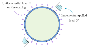
As illustrated in Fig. 1, the coating is modelled as a circular rod, which is subjected in its undeformed configuration to a uniform load ΠΠ\Pi, acting radially and so producing only a uniform axial prestress, N0subscript𝑁0N_{0}, without shear force T0subscript𝑇0T_{0} and bending moment M0subscript𝑀0M_{0},

N0=ΠR,T0=M0=0,formulae-sequencesubscript𝑁0Π𝑅subscript𝑇0subscript𝑀00N_{0}=-\Pi\,R,\quad T_{0}=M_{0}=0, (4)

where ΠΠ\Pi is positive when directed towards the centre of the rod, in which case N0subscript𝑁0N_{0} is negative, i.e. compressive. From the circular reference configuration, superimposed incremental deformations are analysed as induced by the application of an external incremental load 𝐪˙βsuperscript˙𝐪𝛽\dot{\mathbf{q}}^{\beta}, to be detailed below. Assuming the inextensibility of the rod, the incremental kinematics is governed by

5u˙rθ5+(2+ΠR3B)3u˙rθ3+(1+2ΠR3B)u˙rθΠR3Bu˙θ+𝔖=0,u˙r+u˙θθ=0,formulae-sequencesuperscript5subscript˙𝑢𝑟superscript𝜃52Πsuperscript𝑅3𝐵superscript3subscript˙𝑢𝑟superscript𝜃312Πsuperscript𝑅3𝐵subscript˙𝑢𝑟𝜃Πsuperscript𝑅3𝐵subscript˙𝑢𝜃𝔖0subscript˙𝑢𝑟subscript˙𝑢𝜃𝜃0\frac{\partial^{5}{\dot{u}_{r}}}{\partial{\theta^{5}}}+\left(2+\frac{{\Pi}R^{3}}{B}\right)\frac{\partial^{3}{\dot{u}_{r}}}{\partial{\theta^{3}}}+\left(1+2\frac{{\Pi}R^{3}}{B}\right)\frac{\partial{\dot{u}_{r}}}{\partial{\theta}}-\frac{\Pi R^{3}}{B}\dot{u}_{\theta}+\mathfrak{S}=0,\quad\dot{u}_{r}+\frac{\partial\dot{u}_{\theta}}{\partial{\theta}}=0, (5)

where a superimposed dot denotes an incremental quantity and the external load is specified through

𝔖=R4B(𝐪˙θ𝐦0+2𝐪˙𝐭0),𝔖superscript𝑅4𝐵˙𝐪𝜃subscript𝐦02˙𝐪subscript𝐭0\mathfrak{S}=-\frac{R^{4}}{B}\left(\frac{\partial\dot{\mathbf{q}}}{\partial\theta}\cdot{\mathbf{m}}_{0}+2\dot{\mathbf{q}}\cdot\mathbf{t}_{0}\right), (6)

function of the incremental load 𝐪˙˙𝐪\dot{\mathbf{q}} applied to the rod. The latter is not only due to 𝐪˙βsuperscript˙𝐪𝛽\dot{\mathbf{q}}^{\beta}, but also contains components due to both the incremental interaction with the disk (which produces incremental traction when perturbed) and how the specific type of radial load ΠΠ\Pi ‘reacts’ to incremental deformation. In particular, the annular rod enclosing the elastic disk is subject to a uniform radial load ΠΠ\Pi, selected between different types, which may be generated by the environment external to the disk/coating system or may be internally generated as a traction exchange between coating and disk, consequent to a shrink-fit or thermal operation. In particular, the radial force distribution ΠΠ\Pi may be as follows.

  • Applied by the external environment on the outer surface of the coating. This ΠΠ\Pi can be of three different natures: (i.) hydrostatic pressure, (ii.) centrally directed (towards the initial centre of the disk), and (iii.) dead.

  • Internally generated through traction exchange between coating and disk as induced by a preliminary shrink-fit process or differential variation of temperature between disk and coating. The account of this process enables the determination of the specific value of ΠΠ\Pi to be used for incremental analysis where it is treated as a dead load, type (iii.) above.

The above loads define the reference configuration for the coated disk system, so that the rod is uniformly prestressed by an axial force, which can be either tensile or compressive, while the inner disk is either unloaded or slightly loaded through a uniform mean stress. This reference configuration is perturbed through the application of an additional incremental external load (preserving the overall equilibrium of the coating/disk system) 𝐪˙βsuperscript˙𝐪𝛽\dot{\mathbf{q}}^{\beta}, with tangential and radial components q˙βsuperscript˙𝑞𝛽\dot{q}^{\beta} and p˙βsuperscript˙𝑝𝛽\dot{p}^{\beta} (Fig. 1),

𝐪˙β=q˙β𝐭0p˙β𝐦0.superscript˙𝐪𝛽superscript˙𝑞𝛽subscript𝐭0superscript˙𝑝𝛽subscript𝐦0\dot{\mathbf{q}}^{\beta}=\dot{q}^{\beta}\mathbf{t}_{0}-\dot{p}^{\beta}\mathbf{m}_{0}. (7)

The perturbation induces an incremental change in the reference configuration, so that the external load ΠΠ\Pi and the internal tractions at the disk/coating contact also produce increments of loads for the rod. Summing up all these contributions, the incremental load for the rod, 𝐪˙˙𝐪\dot{\mathbf{q}}, results as the sum

𝐪˙=𝐪˙Π+𝐪˙β+𝐪˙σ,˙𝐪superscript˙𝐪Πsuperscript˙𝐪𝛽superscript˙𝐪𝜎\dot{\mathbf{q}}=\dot{\mathbf{q}}^{\Pi}+\dot{\mathbf{q}}^{\beta}+\dot{\mathbf{q}}^{\sigma}, (8)

where, introducing \mathscr{M} to rule the shear transmission properties at the interface (=11\mathscr{M}=1 for perfect bonding between disk and coating or =00\mathscr{M}=0 for slip contact),

𝐪˙σ=b(σ˙rr𝐦0+σ˙rθ𝐭0)r=R,superscript˙𝐪𝜎𝑏subscriptsubscript˙𝜎𝑟𝑟subscript𝐦0subscript˙𝜎𝑟𝜃subscript𝐭0𝑟𝑅\dot{\mathbf{q}}^{\sigma}=-b\left(\dot{\sigma}_{rr}\mathbf{m}_{0}+\mathscr{M}\dot{\sigma}_{r\theta}\mathbf{t}_{0}\right)_{r=R}, (9)

is the incremental traction exchanged between disk and coating, where b𝑏b is the out-of-plane thickness of the coating and σ˙rrsubscript˙𝜎𝑟𝑟\dot{\sigma}_{rr} and σ˙rθsubscript˙𝜎𝑟𝜃\dot{\sigma}_{r\theta} are the incremental stress components on the boundary of the disk. The term 𝐪˙Πsuperscript˙𝐪Π\dot{\mathbf{q}}^{\Pi} in eq. (8) describes the behaviour of the radial load during the increment, which may vary according to the specific dependence postulated for the force on the deformation. The following three incremental loadings are included in the formulation, each defining the term 𝐪˙Πsuperscript˙𝐪Π\dot{\mathbf{q}}^{\Pi} as

𝐪˙Π=Π×{(u˙rsu˙θR)𝐭0when Π is a hydrostatic pressure (i.)u˙θR𝐭0when Π is a centrally directed load (ii.)𝟎when Π is a dead load (iii.)superscript˙𝐪ΠΠcasessubscript˙𝑢𝑟𝑠subscript˙𝑢𝜃𝑅subscript𝐭0when Π is a hydrostatic pressure (i.)subscript˙𝑢𝜃𝑅subscript𝐭0when Π is a centrally directed load (ii.)0when Π is a dead load (iii.)\dot{\mathbf{q}}^{\Pi}=\Pi\times\left\{\begin{array}[]{ll}\left(\dfrac{\partial{\dot{u}_{r}}}{\partial{s}}-\dfrac{\dot{u}_{\theta}}{R}\right)\mathbf{t}_{0}&\text{when $\Pi$ is a hydrostatic pressure (i.)}\\[11.38109pt] -\dfrac{\dot{u}_{\theta}}{R}\,\mathbf{t}_{0}&\text{when $\Pi$ is a centrally directed load (ii.)}\\[8.53581pt] \bf{0}&\text{when $\Pi$ is a dead load (iii.)}\end{array}\right. (10)

and hence, the term 𝔖𝔖\mathfrak{S} in equation (6) becomes

𝔖Π=ΠR3B×{u˙rθ+u˙θwhen Π is a hydrostatic pressure (i.)u˙θwhen Π is a centrally directed load (ii.)0when Π is a dead load (iii.).superscript𝔖ΠΠsuperscript𝑅3𝐵casessubscript˙𝑢𝑟𝜃subscript˙𝑢𝜃when Π is a hydrostatic pressure (i.)subscript˙𝑢𝜃when Π is a centrally directed load (ii.)0when Π is a dead load (iii.)\mathfrak{S}^{\Pi}=\frac{\Pi R^{3}}{B}\times\left\{\begin{array}[]{ll}-\dfrac{\partial\dot{u}_{r}}{\partial\theta}+\dot{u}_{\theta}&\text{when $\Pi$ is a hydrostatic pressure (i.)}\\[8.53581pt] \dot{u}_{\theta}&\text{when $\Pi$ is a centrally directed load (ii.)}\\[8.53581pt] 0&\text{when $\Pi$ is a dead load (iii.)}.\end{array}\right. (11)

The hydrostatic pressure is a well-known type of load, which often can simply be realized, while a centrally directed load, passing through a fixed point (the centre of the circular ring, in the present case), requires a rather complicated realization, for instance, through inextensible cables. The most complicated loading condition for a circular geometry is the simpler for a rectilinear rod, namely, the dead loading. This can hardly be realized in a circular geometry, except when, instead of an external load, the prestress N0subscript𝑁0N_{0} in the rod is generated through a thermal variation (in the presence of a mismatch in the thermal expansion coefficients of disk and rod) or a ‘shrink-fit’ forcing of the coating on the disk. In this case, a residual stress, rather than a prestress, is generated, producing a radial pressure ΠΠ\Pi on the coating, but the equations governing the problem become the same as the dead load, so that Π˙=0˙Π0\dot{\Pi}=0.

2.2 The disk coated with the prestressed rod

2.2.1 Incremental applied load on the disk/coating system

Concerning the problem sketched in Fig. 1, the disk is characterized by a shear modulus μdsuperscript𝜇d\mu^{\text{d}}, Lamé constant λdsuperscript𝜆d\lambda^{\text{d}}, Young’s modulus Edsuperscript𝐸dE^{\text{d}}, Poisson’s ratio νdsuperscript𝜈d\nu^{\text{d}} and it is coated along its boundary L𝐿L by the circular rod introduced in the previous section.

In a polar coordinates system (𝐞r,𝐞θ)subscript𝐞𝑟subscript𝐞𝜃(\mathbf{e}_{r},\mathbf{e}_{\theta}), the incremental displacement of a point of the disk can be represented as

𝐮˙d=u˙rd𝐞r+u˙θd𝐞θ,superscript˙𝐮dsubscriptsuperscript˙𝑢d𝑟subscript𝐞𝑟subscriptsuperscript˙𝑢d𝜃subscript𝐞𝜃\dot{\mathbf{u}}^{\text{d}}=\dot{u}^{\text{d}}_{r}\,\mathbf{e}_{r}+\dot{u}^{\text{d}}_{\theta}\,\mathbf{e}_{\theta}, (12)

where urdsubscriptsuperscript𝑢d𝑟u^{\text{d}}_{r} and uθdsubscriptsuperscript𝑢d𝜃u^{\text{d}}_{\theta} are radial and tangential components.

Two initial stress configurations will be considered for the disk/coating system, before an additional incremental load, 𝐪˙βsuperscript˙𝐪𝛽\dot{\mathbf{q}}^{\beta} in Fig. 1, is applied on its boundary. These are:

  1. 1.

    The radial load ΠΠ\Pi is acting on the external surface of the coating and, as a consequence, a state of prestress is produced (in terms of the internal force N0subscript𝑁0N_{0}) in the coating, but inside of the disk the material remains unstressed, because the coating is modelled as an axially-inextensible rod, carrying N0subscript𝑁0N_{0} without deformation.

  2. 2.

    A uniform radial load is not applied on the external, but on the internal surface of the coating, where a radial force distribution ΠΠ\Pi exists, acting on both coating and disk with an opposed sign, as a consequence of a previous ‘shrink/fit’ or a thermal mismatch operation on the disk/coating system. This operation is assumed to generate a strong axial force N0subscript𝑁0N_{0} in the coating, but to leave only a weak state of stress inside of the disk (that will be simply summed to further incremental stress).

In the two above cases (1)-(2), the stress in the elastic disk is either null or assumed small before the incremental deformation occurs. In this circumstance, the equations of finite elasticity reduce to the linear theory, so that the incremental response of the disk is governed by Hooke’s law

𝝈˙=λd(tr𝐃)𝐈+2μd𝐃,˙𝝈superscript𝜆dtr𝐃𝐈2superscript𝜇d𝐃\dot{\bm{\sigma}}=\lambda^{\text{d}}(\operatorname{tr}\mathbf{D})\,\mathbf{I}+2\mu^{\text{d}}\,\mathbf{D}, (13)

where 𝐃=(𝐮˙𝐮˙T)/2𝐃˙𝐮superscript˙𝐮𝑇2\mathbf{D}=(\nabla\dot{\mathbf{u}}-\nabla\dot{\mathbf{u}}^{T})/2 is the Eulerian strain incremental tensor, and the increments in the first Piola-Kirchhoff and Cauchy stresses coincide, 𝐒˙=𝝈˙˙𝐒˙𝝈\dot{\mathbf{S}}=\dot{\bm{\sigma}}. Note that in the above case (2) the incremental solution has to be summed to the state of prestress in the disk, while in both cases the incremental solution is superimposed on the prestress in the annular coating.

In summary, the elastic disk is subject to incremental tractions, transmitted from its interaction with the coating. An incremental load, 𝐪˙βsuperscript˙𝐪𝛽\dot{\mathbf{q}}^{\beta} in Fig. 1, is applied to the latter. This load is summed to a previously-applied and uniformly-distributed radial load, ΠΠ\Pi in Fig. 1, which may be induced by an either external or internal agent to the system. When applied from the external environment, the radial force distribution ΠΠ\Pi does not produce any deformation in the disk and in the coating, due to the assumption of inextensibility of the latter, where an axial prestress, N0subscript𝑁0N_{0} in Fig. 1 is only generated. Alternatively, the state of prestress is produced by some shrink-fit operation, generating an internal radial load ΠΠ\Pi, which induces a prestress in the coating and is assumed to leave the elastic disk only weakly prestressed. In all cases, the effects of the prestress are implemented in the rod forming the coating, which obeys the linearized equations governing prestressed circular rods, while the elastic core inside the coating reacts linearly without a direct effect of prestress. The elastic core may be either fully connected to the coating or only radially bonded, to realize therefore a ‘slip contact’.

Implementing the incremental load (8) in equation (5) leads to the equations governing the incremental kinematics of the coating in contact with the disk

5u˙rcθ5+(2+ΠR3B)3u˙rcθ3+(1+2ΠR3B)u˙rcθΠR3Bu˙θc+𝔖Π+𝔖σ+𝔖β=0,superscript5subscriptsuperscript˙𝑢c𝑟superscript𝜃52Πsuperscript𝑅3𝐵superscript3subscriptsuperscript˙𝑢c𝑟superscript𝜃312Πsuperscript𝑅3𝐵subscriptsuperscript˙𝑢c𝑟𝜃Πsuperscript𝑅3𝐵subscriptsuperscript˙𝑢c𝜃superscript𝔖Πsuperscript𝔖𝜎superscript𝔖𝛽0\displaystyle\frac{\partial^{5}{\dot{u}^{\text{c}}_{r}}}{\partial{\theta^{5}}}+\left(2+\frac{{\Pi}R^{3}}{B}\right)\frac{\partial^{3}{\dot{u}^{\text{c}}_{r}}}{\partial{\theta^{3}}}+\left(1+2\frac{{\Pi}R^{3}}{B}\right)\frac{\partial{\dot{u}^{\text{c}}_{r}}}{\partial{\theta}}-\frac{\Pi R^{3}}{B}\dot{u}^{\text{c}}_{\theta}+\mathfrak{S}^{\Pi}+\mathfrak{S}^{\sigma}+\mathfrak{S}^{\beta}=0, (14)
u˙rcR+u˙θcs=0,subscriptsuperscript˙𝑢c𝑟𝑅subscriptsuperscript˙𝑢c𝜃𝑠0\displaystyle\frac{\dot{u}^{\text{c}}_{r}}{R}+\frac{\partial\dot{u}^{\text{c}}_{\theta}}{\partial{s}}=0,

where the superscript ‘c’ stands for ‘coating’ and

𝔖j=R4B(𝐪˙jθ𝐦0+2𝐪˙j𝐭0),j=Π,σ,β.formulae-sequencesuperscript𝔖jsuperscript𝑅4𝐵superscript˙𝐪j𝜃subscript𝐦02superscript˙𝐪jsubscript𝐭0jΠ𝜎𝛽\mathfrak{S}^{\text{j}}=-\frac{R^{4}}{B}\left(\frac{\partial\dot{\mathbf{q}}^{\text{j}}}{\partial\theta}\cdot{\mathbf{m}}_{0}+2\dot{\mathbf{q}}^{\text{j}}\cdot\mathbf{t}_{0}\right),\quad\text{j}=\Pi,\,\sigma,\,\beta. (15)

The derivatives involved in equation (15) assume the forms

𝐪˙σs=(σ˙rθs+1Rσ˙rr)r=R𝐭0+(Rσ˙rθσ˙rrs)r=R𝐦0,superscript˙𝐪𝜎𝑠subscriptsubscript˙𝜎𝑟𝜃𝑠1𝑅subscript˙𝜎𝑟𝑟𝑟𝑅subscript𝐭0subscript𝑅subscript˙𝜎𝑟𝜃subscript˙𝜎𝑟𝑟𝑠𝑟𝑅subscript𝐦0\displaystyle\frac{\partial\dot{\mathbf{q}}^{\sigma}}{\partial{s}}=-\left(\mathscr{M}\frac{\partial{\dot{\sigma}_{r\theta}}}{\partial{s}}+\frac{1}{R}\dot{\sigma}_{rr}\right)_{r=R}\mathbf{t}_{0}+\left(\frac{\mathscr{M}}{R}\dot{\sigma}_{r\theta}-\frac{\partial{\dot{\sigma}_{rr}}}{\partial{s}}\right)_{r=R}\mathbf{m}_{0}, (16)
𝐪˙βs=(q˙βsp˙βR)𝐭0(p˙βs+q˙βR)𝐦0,superscript˙𝐪𝛽𝑠superscript˙𝑞𝛽𝑠superscript˙𝑝𝛽𝑅subscript𝐭0superscript˙𝑝𝛽𝑠superscript˙𝑞𝛽𝑅subscript𝐦0\displaystyle\frac{\partial\dot{\mathbf{q}}^{\beta}}{\partial{s}}=\left(\frac{\partial\dot{q}^{\beta}}{\partial s}-\frac{\dot{p}^{\beta}}{R}\right)\mathbf{t}_{0}-\left(\frac{\partial\dot{p}^{\beta}}{\partial s}+\frac{\dot{q}^{\beta}}{R}\right)\mathbf{m}_{0},

while the terms 𝔖σsuperscript𝔖𝜎\mathfrak{S}^{\sigma} and 𝔖βsuperscript𝔖𝛽\mathfrak{S}^{\beta} in equation (15) become

𝔖σ=R4bB(Rσ˙rrs+σ˙rθ)r=R,𝔖β=R4B(p˙βs+q˙β).formulae-sequencesuperscript𝔖𝜎superscript𝑅4𝑏𝐵subscript𝑅subscript˙𝜎𝑟𝑟𝑠subscript˙𝜎𝑟𝜃𝑟𝑅superscript𝔖𝛽superscript𝑅4𝐵superscript˙𝑝𝛽𝑠superscript˙𝑞𝛽\mathfrak{S}^{\sigma}=\frac{R^{4}b}{B}\left(R\frac{\partial{\dot{\sigma}_{rr}}}{\partial{s}}+\mathscr{M}\dot{\sigma}_{r\theta}\right)_{r=R},\quad\mathfrak{S}^{\beta}=-\frac{R^{4}}{B}\left(-\frac{\partial\dot{p}^{\beta}}{\partial s}+\dot{q}^{\beta}\right). (17)

When the coating is either perfectly bonded to the disk or radially connected but tangentially disconnected, the following boundary conditions (displacement continuity in the former case, partial continuity and vanishing of shear stress in the latter) have to be imposed, respectively,

u˙rc=u˙rd|r=R,andu˙θc=u˙θd|r=Rperfect bondingorσ˙rθ|r=R=0slip contact.subscriptsuperscript˙𝑢c𝑟evaluated-atsubscriptsuperscript˙𝑢d𝑟𝑟𝑅andsubscriptsubscriptsuperscript˙𝑢c𝜃evaluated-atsubscriptsuperscript˙𝑢d𝜃𝑟𝑅perfect bondingorsubscriptevaluated-atsubscript˙𝜎𝑟𝜃𝑟𝑅0slip contact\dot{u}^{\text{c}}_{r}=\dot{u}^{\text{d}}_{r}\big{|}_{r=R},\quad\text{and}\quad\underbrace{\dot{u}^{\text{c}}_{\theta}=\dot{u}^{\text{d}}_{\theta}\big{|}_{r=R}}_{\text{perfect bonding}}\quad\text{or}\quad\underbrace{\dot{\sigma}_{r\theta}\big{|}_{r=R}=0}_{\text{slip contact}}. (18)

Moreover,the governing equation (14)1 can be rewritten as

5u˙rcθ5+23u˙rcθ3+u˙rcθ+ΠR3B(3u˙rcθ3+2u˙rcθu˙θc)+𝔖Π+𝔖σ+𝔖β=0,superscript5subscriptsuperscript˙𝑢c𝑟superscript𝜃52superscript3subscriptsuperscript˙𝑢c𝑟superscript𝜃3subscriptsuperscript˙𝑢c𝑟𝜃Πsuperscript𝑅3𝐵superscript3subscriptsuperscript˙𝑢c𝑟superscript𝜃32subscriptsuperscript˙𝑢c𝑟𝜃subscriptsuperscript˙𝑢c𝜃superscript𝔖Πsuperscript𝔖𝜎superscript𝔖𝛽0\frac{\partial^{5}{\dot{u}^{\text{c}}_{r}}}{\partial{\theta^{5}}}+2\frac{\partial^{3}{\dot{u}^{\text{c}}_{r}}}{\partial{\theta^{3}}}+\frac{\partial{\dot{u}^{\text{c}}_{r}}}{\partial{\theta}}+\frac{\Pi R^{3}}{B}\left(\frac{\partial^{3}{\dot{u}^{\text{c}}_{r}}}{\partial{\theta^{3}}}+2\frac{\partial{\dot{u}^{\text{c}}_{r}}}{\partial{\theta}}-\dot{u}^{\text{c}}_{\theta}\right)+\mathfrak{S}^{\Pi}+\mathfrak{S}^{\sigma}+\mathfrak{S}^{\beta}=0, (19)

which is valid for all load types listed in equation (11) and for all the interface conditions specified with eqs. (18), except for the combination of dead load and slip interface, when 𝔖Π=0superscript𝔖Π0\mathfrak{S}^{\Pi}=0 in equation (14) and =00\mathscr{M}=0 in equation (17)1. In the latter case, the following equation governs the problem

6u˙rcθ6+(2+ΠR3B)4u˙rcθ4+(1+2ΠR3B)2u˙rcθ2+ΠR3Bu˙rc+R5B(bR2σ˙rrθ2+2p˙βθ2q˙βθ)=0.superscript6subscriptsuperscript˙𝑢c𝑟superscript𝜃62Πsuperscript𝑅3𝐵superscript4subscriptsuperscript˙𝑢c𝑟superscript𝜃412Πsuperscript𝑅3𝐵superscript2subscriptsuperscript˙𝑢c𝑟superscript𝜃2Πsuperscript𝑅3𝐵subscriptsuperscript˙𝑢c𝑟superscript𝑅5𝐵𝑏𝑅superscript2subscript˙𝜎𝑟𝑟superscript𝜃2superscript2superscript˙𝑝𝛽superscript𝜃2superscript˙𝑞𝛽𝜃0\frac{\partial^{6}{\dot{u}^{\text{c}}_{r}}}{\partial{\theta^{6}}}+\left(2+\frac{\Pi R^{3}}{B}\right)\frac{\partial^{4}{\dot{u}^{\text{c}}_{r}}}{\partial{\theta^{4}}}+\left(1+2\frac{\Pi R^{3}}{B}\right)\frac{\partial^{2}{\dot{u}^{\text{c}}_{r}}}{\partial{\theta^{2}}}+\frac{\Pi R^{3}}{B}\dot{u}^{\text{c}}_{r}+\frac{R^{5}}{B}\left(\frac{b}{R}\frac{\partial^{2}\dot{\sigma}_{rr}}{\partial{\theta^{2}}}+\frac{\partial^{2}\dot{p}^{\beta}}{\partial\theta^{2}}-\frac{\partial\dot{q}^{\beta}}{\partial\theta}\right)=0. (20)

2.2.2 Complex variable formulation for the disk

In a complex variable formulation, the disk is a simple connected circular region, bounded by a non-intersecting smooth curve L𝐿L, so that every point can be represented through the complex variable z=x1+ix2𝑧subscript𝑥1𝑖subscript𝑥2z=x_{1}+ix_{2}, where x1subscript𝑥1x_{1} and x2subscript𝑥2x_{2} are the coordinates of the point and i=1𝑖1i=\sqrt{-1} is the imaginary unit. Moreover, denoting with r𝑟r the distance from the point z𝑧z to the origin zc=0subscript𝑧𝑐0z_{c}=0 and with θ𝜃\theta the angle (positive when anticlockwise) between x1subscript𝑥1x_{1} and the radius r𝑟r, in a polar coordinate system (r,θ)𝑟𝜃(r,\theta) it is z=reiθ𝑧𝑟superscript𝑒𝑖𝜃z=re^{i\theta}. Following [22], the following notation is introduced

g(z)=Rz=R(x1+ix2),g(z)=1Rg2(z),g′′(z)=2R2g3(z),formulae-sequence𝑔𝑧𝑅𝑧𝑅subscript𝑥1𝑖subscript𝑥2formulae-sequencesuperscript𝑔𝑧1𝑅superscript𝑔2𝑧superscript𝑔′′𝑧2superscript𝑅2superscript𝑔3𝑧\displaystyle g(z)=\frac{R}{z}=\frac{R}{(x_{1}+ix_{2})},\quad g^{\prime}(z)=-\frac{1}{R}g^{2}(z),\quad g^{\prime\prime}(z)=\frac{2}{R^{2}}g^{3}(z), (21)
g(z)¯=R2r2g1(z),r=x12+x22.formulae-sequence¯𝑔𝑧superscript𝑅2superscript𝑟2superscript𝑔1𝑧𝑟superscriptsubscript𝑥12superscriptsubscript𝑥22\displaystyle\overline{g(z)}=\frac{R^{2}}{r^{2}}g^{-1}(z),\quad r=\sqrt{x_{1}^{2}+x_{2}^{2}}.

where a prime denotes the derivative with respect to z𝑧z and a superimposed bar the complex conjugate. By setting r=R𝑟𝑅r=R in equations (21), the following relations for points τ=Reiθ𝜏𝑅superscript𝑒𝑖𝜃\tau=R\,e^{i\theta} on the boundary of the disk can be derived

g(τ)=Rτ,g(τ)¯=Rτ¯=g1(τ),g(τ)=1Rg2(τ).formulae-sequenceformulae-sequence𝑔𝜏𝑅𝜏¯𝑔𝜏𝑅¯𝜏superscript𝑔1𝜏superscript𝑔𝜏1𝑅superscript𝑔2𝜏g(\tau)=\frac{R}{\tau},\quad\overline{g(\tau)}=\frac{R}{\overline{\tau}}=g^{-1}(\tau),\quad g^{\prime}(\tau)=-\frac{1}{R}g^{2}(\tau). (22)

The elastic displacement and stress fields can be determined everywhere in the disk via Kolosov-Muskhelishvili complex potentials φ(z)𝜑𝑧\varphi(z) and ψ(z)𝜓𝑧\psi(z) as [23]

{2μdud(z)=κdφ(z)zφ(z)¯ψ(z)¯,σ11d+σ22d=4Re(φ(z)),σ22dσ11d+2iσ12d=2[z¯φ′′(z)+ψ(z)],\left\{\begin{aligned} &2\mu^{\text{d}}{u^{\text{d}}(z)}=\kappa^{\text{d}}\varphi(z)-z\overline{\varphi^{\prime}(z)}-\overline{\psi(z)},\\ &\sigma^{\text{d}}_{11}+\sigma^{\text{d}}_{22}=4\,\operatorname{Re}\left(\varphi^{\prime}(z)\right),\\ &\sigma^{\text{d}}_{22}-\sigma^{\text{d}}_{11}+2i\sigma^{\text{d}}_{12}=2\left[\overline{z}\varphi^{\prime\prime}(z)+\psi^{\prime}(z)\right],\end{aligned}\right. (23)

where the prime indicates derivation with respect to the variable z𝑧z while ReRe\mathrm{Re} and ImIm\mathrm{Im} denote real and the imaginary parts, respectively. The components of the incremental Eulerian strain tensor 𝐃𝐃\mathbf{D} are linked to the complex potentials through

{D11d+D22d=212νdμdRe(φ(z)),D22dD11d+2iD12d=1μd[z¯φ′′(z)+ψ(z)].casessubscriptsuperscript𝐷d11subscriptsuperscript𝐷d22212superscript𝜈dsuperscript𝜇dResuperscript𝜑𝑧missing-subexpressionmissing-subexpressionsubscriptsuperscript𝐷d22subscriptsuperscript𝐷d112𝑖subscriptsuperscript𝐷d121superscript𝜇ddelimited-[]¯𝑧superscript𝜑′′𝑧superscript𝜓𝑧missing-subexpressionmissing-subexpression\displaystyle\left\{\begin{array}[]{lll}\displaystyle D^{\text{d}}_{11}+D^{\text{d}}_{22}=2\frac{1-2\nu^{\text{d}}}{\mu^{\text{d}}}\mathrm{Re}\!\left(\varphi^{\prime}\left(z\right)\right),\\ \displaystyle D^{\text{d}}_{22}-D^{\text{d}}_{11}+2iD^{\text{d}}_{12}=\frac{1}{\mu^{\text{d}}}\left[\overline{z}\varphi^{\prime\prime}\left(z\right)+\psi^{\prime}\left(z\right)\right].\end{array}\right. (24)

At every point τ=Reiθ𝜏𝑅superscript𝑒𝑖𝜃\tau=R\,e^{i\theta} on the boundary of the disk the following complex Fourier representation for the displacement is introduced

u1d(τ)+iu2d(τ)=n=1Angn(τ)+n=0Angn(τ),subscriptsuperscript𝑢d1𝜏𝑖subscriptsuperscript𝑢d2𝜏superscriptsubscript𝑛1subscript𝐴𝑛superscript𝑔𝑛𝜏superscriptsubscript𝑛0subscript𝐴𝑛superscript𝑔𝑛𝜏u^{\text{d}}_{1}(\tau)+i\,u^{\text{d}}_{2}(\tau)=\sum_{n=1}^{\infty}{A_{-n}\,g^{n}(\tau)}+\sum_{n=0}^{\infty}{A_{n}\,g^{-n}(\tau)}, (25)

where u1d(τ)subscriptsuperscript𝑢d1𝜏u^{\text{d}}_{1}(\tau) and u2d(τ)subscriptsuperscript𝑢d2𝜏u^{\text{d}}_{2}(\tau) are displacement components and A±nsubscript𝐴plus-or-minus𝑛A_{\pm{n}} are complex coefficients for the moment unknown. The radial and tangential components of the displacement are represented as

urd(τ)=12[ud(τ)g(τ)+ud(τ)¯g1(τ)],uθd(τ)=12i[ud(τ)g(τ)ud(τ)¯g1(τ)].formulae-sequencesubscriptsuperscript𝑢d𝑟𝜏12delimited-[]superscript𝑢d𝜏𝑔𝜏¯superscript𝑢d𝜏superscript𝑔1𝜏subscriptsuperscript𝑢d𝜃𝜏12𝑖delimited-[]superscript𝑢d𝜏𝑔𝜏¯superscript𝑢d𝜏superscript𝑔1𝜏u^{\text{d}}_{r}(\tau)=\frac{1}{2}\left[u^{\text{d}}\left(\tau\right)\,g\left(\tau\right)+\overline{u^{\text{d}}(\tau)}\,g^{-1}(\tau)\right],\quad u^{\text{d}}_{\theta}(\tau)=\frac{1}{2i}\left[u^{\text{d}}(\tau)\,g(\tau)-\overline{u^{\text{d}}(\tau)}\,g^{-1}(\tau)\right]. (26)

Eqns. (25) and (26) lead to

2urd(τ)2iuθd(τ)}=n=1Angn+1(τ)+n=0Ang(n1)(τ)±n=1An¯g(n+1)(τ)±n=0An¯gn1(τ).\left.\begin{aligned} &2u^{\text{d}}_{r}(\tau)\\ &2i\,u^{\text{d}}_{\theta}(\tau)\end{aligned}\right\}=\sum_{n=1}^{\infty}{A_{-n}\,g^{n+1}(\tau)}+\sum_{n=0}^{\infty}{A_{n}\,g^{-\left(n-1\right)}(\tau)}\pm\sum_{n=1}^{\infty}{\overline{A_{-n}}\,g^{-\left(n+1\right)}(\tau)}\pm\sum_{n=0}^{\infty}{\overline{A_{n}}\,g^{n-1}(\tau)}. (27)

The complex combination of the stresses acting at a point τL𝜏𝐿\tau\in{L} of the disk can be introduced

σrrd(τ)+iσrθd(τ)=n=1Bngn(τ)+n=0Bngn(τ),subscriptsuperscript𝜎d𝑟𝑟𝜏𝑖subscriptsuperscript𝜎d𝑟𝜃𝜏superscriptsubscript𝑛1subscript𝐵𝑛superscript𝑔𝑛𝜏superscriptsubscript𝑛0subscript𝐵𝑛superscript𝑔𝑛𝜏\sigma^{\text{d}}_{rr}(\tau)+i\,\sigma^{\text{d}}_{r\theta}(\tau)=\sum_{n=1}^{\infty}{B_{-n}\,g^{n}(\tau)}+\sum_{n=0}^{\infty}{B_{n}\,g^{-n}(\tau)}, (28)

where the complex coefficients A±nsubscript𝐴plus-or-minus𝑛A_{\pm{n}} and B±nsubscript𝐵plus-or-minus𝑛B_{\pm{n}} are interrelated as [24]

B1=0,subscript𝐵10\displaystyle B_{-1}=0, B0=4μd(κd1)RRe(A1),subscript𝐵04superscript𝜇dsuperscript𝜅d1𝑅Resubscript𝐴1\displaystyle B_{0}=\frac{4\mu^{\text{d}}}{\left(\kappa^{\text{d}}-1\right)R}\,\operatorname{Re}\left(A_{1}\right), (29)
Bn=2μdR(n1)A1n, for n2,formulae-sequencesubscript𝐵𝑛2superscript𝜇d𝑅𝑛1subscript𝐴1𝑛 for 𝑛2\displaystyle B_{-n}=\frac{2\mu^{\text{d}}}{R}(n-1)\,A_{1-n},\text{ for }n\geq{2}, Bn=2μdκdR(n+1)An+1, for n1.formulae-sequencesubscript𝐵𝑛2superscript𝜇dsuperscript𝜅d𝑅𝑛1subscript𝐴𝑛1 for 𝑛1\displaystyle B_{n}=\frac{2\mu^{\text{d}}}{\kappa^{\text{d}}R}(n+1)\,A_{n+1},\text{ for }n\geq{1}.

The applied external load is represented by the following complex series

qβ(τ)+ipβ(τ)=n=1Dngn(τ)+n=0Dngn(τ),superscript𝑞𝛽𝜏𝑖superscript𝑝𝛽𝜏superscriptsubscript𝑛1subscript𝐷𝑛superscript𝑔𝑛𝜏superscriptsubscript𝑛0subscript𝐷𝑛superscript𝑔𝑛𝜏q^{\beta}(\tau)+i\,p^{\beta}(\tau)=\sum_{n=1}^{\infty}{D_{-n}\,g^{n}(\tau)}+\sum_{n=0}^{\infty}{D_{n}\,g^{-n}(\tau)}, (30)

where D±nsubscript𝐷plus-or-minus𝑛D_{\pm{n}} are complex coefficients that are known once the shape of the external load 𝐪βsuperscript𝐪𝛽\mathbf{q}^{\beta} is prescribed.

For a circular elastic disk, the expressions for the complex potentials φ(z)𝜑𝑧\varphi(z) and ψ(z)𝜓𝑧\psi(z) appearing in eqs. (23) assume the form [25]

φ(z)=2μdκd1Re(A1)g1(z)+2μdκdn=1An+1g(n+1)(z),𝜑𝑧2superscript𝜇dsuperscript𝜅d1Resubscript𝐴1superscript𝑔1𝑧2superscript𝜇dsuperscript𝜅𝑑superscriptsubscript𝑛1subscript𝐴𝑛1superscript𝑔𝑛1𝑧\displaystyle\varphi(z)=\frac{2\mu^{\text{d}}}{\kappa^{\text{d}}-1}\,\operatorname{Re}\left(A_{1}\right)\,g^{-1}(z)+\frac{2\mu^{\text{d}}}{\kappa^{d}}\sum_{n=1}^{\infty}{A_{n+1}\,g^{-\left(n+1\right)}(z)}, (31)
ψ(z)=2μdκd1Re(A1)zc¯R2μdκd[zc¯R+g(z)]n=1(n+1)An+1gn(z)𝜓𝑧2superscript𝜇dsuperscript𝜅d1Resubscript𝐴1¯subscript𝑧𝑐𝑅2superscript𝜇dsuperscript𝜅ddelimited-[]¯subscript𝑧𝑐𝑅𝑔𝑧superscriptsubscript𝑛1𝑛1subscript𝐴𝑛1superscript𝑔𝑛𝑧\displaystyle\psi(z)=-\frac{2\mu^{\text{d}}}{\kappa^{\text{d}}-1}\,\operatorname{Re}\left(A_{1}\right)\,\frac{\overline{z_{c}}}{R}-\frac{2\mu^{\text{d}}}{\kappa^{\text{d}}}\left[\frac{\overline{z_{c}}}{R}+g(z)\right]\sum_{n=1}^{\infty}{\left(n+1\right)A_{n+1}\,g^{-n}(z)}
2μdn=2A1n¯g(n1)(z),2superscript𝜇dsuperscriptsubscript𝑛2¯subscript𝐴1𝑛superscript𝑔𝑛1𝑧\displaystyle\phantom{\psi(z)=}-2\mu^{\text{d}}\sum_{n=2}^{\infty}{\overline{A_{1-n}}\,g^{-\left(n-1\right)}(z)},

and hence, the elastic fields on the boundary and within the disk are known once coefficients A±nsubscript𝐴plus-or-minus𝑛A_{\pm{n}} are found as functions of the known coefficients D±nsubscript𝐷plus-or-minus𝑛D_{\pm{n}}. For brevity, only the case of perfect bonding condition at the interface will be presented in the following, where conditions (18)1-2 are enforced. The other case of slip interface will not be reported, but its derivation follows a procedure analogous to that developed for perfect bonding.

3 Analytic solution for the disk with prestressed coating

3.1 Complex Fourier series form of the governing equations

The complex counterpart of equation (5)2, representing the inextensibility constraint, can be determined using the series representation for the displacement, eq. (27), from which, collecting the terms with the same power of g±n(τ)superscript𝑔plus-or-minus𝑛𝜏g^{\pm{n}}(\tau), it follows [21]

Re(A1)=0,A2=0,An+1=n1n+1A1n¯for n0 and n1.formulae-sequenceResubscript𝐴10formulae-sequencesubscript𝐴20subscript𝐴𝑛1𝑛1𝑛1¯subscript𝐴1𝑛for n0 and n1\operatorname{Re}\left(A_{1}\right)=0,\quad A_{2}=0,\quad A_{n+1}=\frac{n-1}{n+1}\,\overline{A_{1-n}}\quad\text{for $n\neq{0}$ and $n\neq{-1}$}. (32)

From equations (11) and (17)1 for r=R𝑟𝑅r=R, adopting the Fourier series representation introduced before, the terms 𝔖Πsuperscript𝔖Π\mathfrak{S}^{\Pi} and 𝔖σsuperscript𝔖𝜎\mathfrak{S}^{\sigma} in equation (14)1 become [16]

𝔖Π(τ)superscript𝔖Π𝜏\displaystyle\mathfrak{S}^{\Pi}(\tau) =ξΠR32iB{n=1(n)α[Angn+1(τ)An¯g(n+1)(τ)]\displaystyle=\xi\frac{\Pi R^{3}}{2i\,B}\left\{\sum_{n=1}^{\infty}(-n)^{\alpha}\left[A_{-n}\,g^{n+1}(\tau)-\overline{A_{-n}}\,g^{-\left(n+1\right)}(\tau)\right]\right. (33)
+n=0nα[Ang(n1)(τ)An¯gn1(τ)](αξ)[A0g(τ)A0¯g1(τ)]},\displaystyle\left.+\sum_{n=0}^{\infty}n^{\alpha}\left[A_{n}\,g^{-\left(n-1\right)}(\tau)-\overline{A_{n}}\,g^{n-1}(\tau)\right]-\left(\alpha-\xi\right)\left[A_{0}\,g(\tau)-\overline{A_{0}}\,g^{-1}(\tau)\right]\right\},
𝔖σ(τ)superscript𝔖𝜎𝜏\displaystyle\mathfrak{S}^{\sigma}(\tau) =R4b2iB{n=1(n+)[Bngn(τ)Bn¯gn(τ)]n=0(n)[Bngn(τ)Bn¯gn(τ)]},absentsuperscript𝑅4𝑏2𝑖𝐵superscriptsubscript𝑛1𝑛delimited-[]subscript𝐵𝑛superscript𝑔𝑛𝜏¯subscript𝐵𝑛superscript𝑔𝑛𝜏superscriptsubscript𝑛0𝑛delimited-[]subscript𝐵𝑛superscript𝑔𝑛𝜏¯subscript𝐵𝑛superscript𝑔𝑛𝜏\displaystyle=\frac{R^{4}b}{2i\,B}\left\{\sum_{n=1}^{\infty}{\left(n+\mathscr{M}\right)}\left[B_{-n}\,g^{n}(\tau)-\overline{B_{-n}}\,g^{-n}(\tau)\right]-\sum_{n=0}^{\infty}{\left(n-\mathscr{M}\right)}\left[B_{n}\,g^{-n}(\tau)-\overline{B_{n}}\,g^{n}(\tau)\right]\right\},

where (i.) ξ=α=1𝜉𝛼1\xi=\alpha=1 for hydrostatic pressure, (ii.) ξ=1𝜉1\xi=1, α=0𝛼0\alpha=0 for centrally directed load, and (iii.) ξ=0𝜉0\xi=0 for dead load. Isolating the real and the imaginary parts in equation (30) yields

2p˙β(τ)2iq˙β(τ)}=n=1Dngn(τ)+n=0Dngn(τ)±n=1Dn¯gn(τ)±n=0Dn¯gn(τ),\left.\begin{aligned} &2\,\dot{p}^{\beta}(\tau)\\ &2i\,\dot{q}^{\beta}(\tau)\end{aligned}\right\}=\sum_{n=1}^{\infty}D_{-n}\,g^{n}(\tau)+\sum_{n=0}^{\infty}D_{n}\,g^{-n}(\tau)\pm\sum_{n=1}^{\infty}\overline{D_{-n}}\,g^{-n}(\tau)\pm\sum_{n=0}^{\infty}\,\overline{D_{n}}\,g^{n}(\tau), (34)

so that expression (96)2, dτ/ds=ig1(τ)𝑑𝜏𝑑𝑠𝑖superscript𝑔1𝜏d\tau/ds=i\,g^{-1}(\tau) in [24], provides for the term 𝔖βsuperscript𝔖𝛽\mathfrak{S}^{\beta} in eq. (14)1

𝔖β(τ)superscript𝔖𝛽𝜏\displaystyle\mathfrak{S}^{\beta}(\tau) =R4B(n=1(n1)Dngn(τ)n=0(n+1)Dngn(τ)\displaystyle=\frac{R^{4}}{B}\left(\sum_{n=1}^{\infty}{(n-1)D_{-n}\,g^{n}(\tau)}-\sum_{n=0}^{\infty}(n+1)D_{n}\,g^{-n}(\tau)\right. (35)
n=1(n1)Dn¯gn(τ)+n=0(n+1)Dn¯gn(τ)).\displaystyle\phantom{=}\left.-\sum_{n=1}^{\infty}(n-1)\overline{D_{-n}}\,g^{-n}(\tau)+\sum_{n=0}^{\infty}{(n+1)\overline{D_{n}}\,g^{n}(\tau)}\right).

From [16] the following terms appearing in eq. (19) are identified as

5u˙rθ5+23u˙rθ3+u˙rθsuperscript5subscript˙𝑢𝑟superscript𝜃52superscript3subscript˙𝑢𝑟superscript𝜃3subscript˙𝑢𝑟𝜃\displaystyle\frac{\partial^{5}\dot{u}_{r}}{\partial\theta^{5}}+2\frac{\partial^{3}\dot{u}_{r}}{\partial\theta^{3}}+\frac{\partial\dot{u}_{r}}{\partial\theta} =12i{n=1n2(n+1)(n+2)2[Angn+1An¯g(n+1)]\displaystyle=\frac{1}{2i}\left\{\sum_{n=1}^{\infty}n^{2}\left(n+1\right)\left(n+2\right)^{2}\left[A_{-n}\,g^{n+1}-\overline{A_{-n}}\,g^{-\left(n+1\right)}\right]\right. (36)
n=3n2(n1)(n2)2[Ang(n1)An¯gn1]},\displaystyle\phantom{=}\left.-\sum_{n=3}^{\infty}{n^{2}\left(n-1\right)\left(n-2\right)^{2}\left[A_{n}\,g^{-\left(n-1\right)}-\overline{A_{n}}\,g^{n-1}\right]}\right\},
3u˙rθ3+2u˙rθu˙θsuperscript3subscript˙𝑢𝑟superscript𝜃32subscript˙𝑢𝑟𝜃subscript˙𝑢𝜃\displaystyle\frac{\partial^{3}{\dot{u}_{r}}}{\partial{\theta^{3}}}+2\frac{\partial{\dot{u}_{r}}}{\partial{\theta}}-\dot{u}_{\theta} =12i{n=1n(n23n+1)[Ang(n1)(τ)An¯gn1]\displaystyle=\frac{1}{2i}\left\{\sum_{n=1}^{\infty}n\left(n^{2}-3n+1\right)\left[A_{n}\,g^{-\left(n-1\right)}(\tau)-\overline{A_{n}}\,g^{n-1}\right]\right.
n=1n(n2+3n+1)[Angn+1An¯g(n+1)]},\displaystyle\phantom{=}\left.-\sum_{n=1}^{\infty}n\left(n^{2}+3n+1\right)\left[A_{-n}\,g^{n+1}-\overline{A_{-n}}\,g^{-\left(n+1\right)}\right]\right\},

so that a substitution of expressions (36), (33) and (35) leads to the following form of equation (19)

n=1n2(n+1)(n+2)2[Angn+1(τ)An¯g(n+1)(τ)]n=3n2(n1)(n2)2[Ang(n1)(τ)An¯gn1(τ)]+ΠR3B{n=1n(n23n+1)[Ang(n1)(τ)An¯gn1(τ)]n=1n(n2+3n+1)[Angn+1(τ)An¯g(n+1)(τ)]}+bR4B{n=1(n+)[Bngn(τ)Bn¯gn(τ)]n=0(n)[Bngn(τ)Bn¯gn(τ)]}+R4B[n=1(n1)Dngn(τ)n=0(n+1)Dngn(τ)n=1(n1)Dn¯gn(τ)+n=0(n+1)Dn¯gn(τ)]+𝔖Π=0.superscriptsubscript𝑛1superscript𝑛2𝑛1superscript𝑛22delimited-[]subscript𝐴𝑛superscript𝑔𝑛1𝜏¯subscript𝐴𝑛superscript𝑔𝑛1𝜏superscriptsubscript𝑛3superscript𝑛2𝑛1superscript𝑛22delimited-[]subscript𝐴𝑛superscript𝑔𝑛1𝜏¯subscript𝐴𝑛superscript𝑔𝑛1𝜏Πsuperscript𝑅3𝐵superscriptsubscript𝑛1𝑛superscript𝑛23𝑛1delimited-[]subscript𝐴𝑛superscript𝑔𝑛1𝜏¯subscript𝐴𝑛superscript𝑔𝑛1𝜏superscriptsubscript𝑛1𝑛superscript𝑛23𝑛1delimited-[]subscript𝐴𝑛superscript𝑔𝑛1𝜏¯subscript𝐴𝑛superscript𝑔𝑛1𝜏𝑏superscript𝑅4𝐵superscriptsubscript𝑛1𝑛delimited-[]subscript𝐵𝑛superscript𝑔𝑛𝜏¯subscript𝐵𝑛superscript𝑔𝑛𝜏superscriptsubscript𝑛0𝑛delimited-[]subscript𝐵𝑛superscript𝑔𝑛𝜏¯subscript𝐵𝑛superscript𝑔𝑛𝜏superscript𝑅4𝐵delimited-[]superscriptsubscript𝑛1𝑛1subscript𝐷𝑛superscript𝑔𝑛𝜏superscriptsubscript𝑛0𝑛1subscript𝐷𝑛superscript𝑔𝑛𝜏superscriptsubscript𝑛1𝑛1¯subscript𝐷𝑛superscript𝑔𝑛𝜏superscriptsubscript𝑛0𝑛1¯subscript𝐷𝑛superscript𝑔𝑛𝜏superscript𝔖Π0\sum_{n=1}^{\infty}n^{2}\left(n+1\right)\left(n+2\right)^{2}\left[A_{-n}\,g^{n+1}(\tau)-\overline{A_{-n}}\,g^{-\left(n+1\right)}(\tau)\right]\\ -\sum_{n=3}^{\infty}{n^{2}\left(n-1\right)\left(n-2\right)^{2}\left[A_{n}\,g^{-\left(n-1\right)}(\tau)-\overline{A_{n}}\,g^{n-1}(\tau)\right]}+\frac{\Pi{R^{3}}}{B}\left\{\sum_{n=1}^{\infty}n\left(n^{2}-3n+1\right)\right.\\ \left.\left[A_{n}\,g^{-\left(n-1\right)}(\tau)-\overline{A_{n}}\,g^{n-1}(\tau)\right]-\sum_{n=1}^{\infty}{n\left(n^{2}+3n+1\right)\left[A_{-n}\,g^{n+1}(\tau)-\overline{A_{-n}}\,g^{-\left(n+1\right)}(\tau)\right]}\right\}\\ +\frac{bR^{4}}{B}\left\{\sum_{n=1}^{\infty}{\left(n+\mathscr{M}\right)}\left[B_{-n}\,g^{n}(\tau)-\overline{B_{-n}}\,g^{-n}(\tau)\right]-\sum_{n=0}^{\infty}{\left(n-\mathscr{M}\right)}\left[B_{n}\,g^{-n}(\tau)-\overline{B_{n}}\,g^{n}(\tau)\right]\right\}\\ +\frac{R^{4}}{B}\left[\sum_{n=1}^{\infty}(n-1)D_{-n}\,g^{n}(\tau)-\sum_{n=0}^{\infty}{(n+1)D_{n}\,g^{-n}(\tau)}-\sum_{n=1}^{\infty}{(n-1)\overline{D_{-n}}\,g^{-n}(\tau)}\right.\\ \left.+\sum_{n=0}^{\infty}{(n+1)\overline{D_{n}}}\,g^{n}(\tau)\right]+\mathfrak{S}^{\Pi}=0. (37)

Using eqs. (29) and collecting terms with the same power in g±n(τ)superscript𝑔plus-or-minus𝑛𝜏g^{\pm{n}}(\tau) in equation (37), the following cases can be distinguished:

  • For n=0𝑛0n=0 and n=1𝑛1n=1

    (ξ1)ΠIm(A1)RIm(D0)=0,Πξ(αξ)A0+2RD1¯=0,formulae-sequence𝜉1ΠImsubscript𝐴1𝑅Imsubscript𝐷00Π𝜉𝛼𝜉subscript𝐴02𝑅¯subscript𝐷10(\xi-1)\Pi\,\operatorname{Im}(A_{1})-R\,\operatorname{Im}(D_{0})=0,\quad\Pi\,\xi(\alpha-\xi)A_{0}+2R\,\overline{D_{1}}=0, (38)
  • For n2𝑛2n\geq{2}

    A1n=R4κd[(n1)Dn+(n+1)Dn¯]2(n1)[Bκdn2(n21)ΠR3κd(n21Υ(n,α,ξ))+bμdR3Ψ(n,)],subscript𝐴1𝑛superscript𝑅4superscript𝜅ddelimited-[]𝑛1subscript𝐷𝑛𝑛1¯subscript𝐷𝑛2𝑛1delimited-[]𝐵superscript𝜅dsuperscript𝑛2superscript𝑛21Πsuperscript𝑅3superscript𝜅dsuperscript𝑛21Υ𝑛𝛼𝜉𝑏superscript𝜇dsuperscript𝑅3Ψ𝑛A_{1-n}=-\frac{R^{4}\kappa^{\text{d}}\left[(n-1)\,D_{-n}+(n+1)\,\overline{D_{n}}\right]}{2(n-1)\left[B\kappa^{\text{d}}n^{2}(n^{2}-1)-\Pi R^{3}\kappa^{\text{d}}\left(n^{2}-1-\Upsilon(n,\alpha,\xi)\right)+b\mu^{\text{d}}R^{3}\Psi(n,\mathscr{M})\right]}, (39)

    where

    Υ(n,α,ξ)=ξ2[(1)α(n1)α1(n+1)α1],Ψ(n,)=(n+)κd+n.formulae-sequenceΥ𝑛𝛼𝜉𝜉2delimited-[]superscript1𝛼superscript𝑛1𝛼1superscript𝑛1𝛼1Ψ𝑛𝑛superscript𝜅d𝑛\Upsilon(n,\alpha,\xi)=\frac{\xi}{2}\left[(-1)^{\alpha}(n-1)^{\alpha-1}-(n+1)^{\alpha-1}\right],\quad\Psi(n,\mathscr{M})=(n+\mathscr{M})\kappa^{\text{d}}+n-\mathscr{M}. (40)

The denominator in eq. (39), for a radial compressive load, Π>0Π0\Pi>0, may vanish and the corresponding elastic fields become singular. In particular, for a given set of material and geometric parameters (Ec,Ed,κd,R,b,J)superscript𝐸csuperscript𝐸dsuperscript𝜅d𝑅𝑏𝐽(E^{\text{c}},E^{\text{d}},\kappa^{\text{d}},R,b,J) a limit value ΠcrsubscriptΠcr\Pi_{\text{cr}} exists for which the incremental solution for the disk/coating system bifurcates. After this limit value is exceeded, any solution for the coated disk is unstable and thus not anymore valid. The value of the dimensionless bifurcation radial load, as a function of the wave number n𝑛n, was found in [16] as

Π(n)R3B=n2(n21)+μdbR3κdBΨ(n,)(n21)Υ(n,α,ξ),n2,formulae-sequenceΠ𝑛superscript𝑅3𝐵superscript𝑛2superscript𝑛21superscript𝜇d𝑏superscript𝑅3superscript𝜅d𝐵Ψ𝑛superscript𝑛21Υ𝑛𝛼𝜉𝑛2\frac{\Pi(n)R^{3}}{B}=\frac{n^{2}\left(n^{2}-1\right)+\displaystyle\frac{\mu^{\text{d}}bR^{3}}{\kappa^{\text{d}}B}\Psi(n,\mathscr{M})}{\left(n^{2}-1\right)-\displaystyle\Upsilon(n,\alpha,\xi)},\quad n\geq 2, (41)

from which the critical value for the radial load ΠcrsubscriptΠcr\Pi_{\text{cr}} corresponds to the integer number n𝑛n minimizing Π(n)Π𝑛\Pi(n).

3.2 Elastic fields within the prestressed coated disk and internal forces in the coating

Using eqs. (32) and (39) for the coefficients A±nsubscript𝐴plus-or-minus𝑛A_{\pm{n}}, the complex potentials and their derivatives involved in equations (31) assume the form

φ(z)=μdR4n=21Γ(n+1)[(n1)Dn¯+(n+1)Dn]g(n+1)(z),𝜑𝑧superscript𝜇dsuperscript𝑅4superscriptsubscript𝑛21Γ𝑛1delimited-[]𝑛1¯subscript𝐷𝑛𝑛1subscript𝐷𝑛superscript𝑔𝑛1𝑧\displaystyle\varphi(z)=\mu^{\text{d}}R^{4}\sum_{n=2}^{\infty}\frac{1}{\Gamma(n+1)}\left[(n-1)\overline{D_{-n}}+(n+1)D_{n}\right]\,g^{-(n+1)}(z), (42)
φ(z)=μdR3n=21Γ[(n1)Dn¯+(n+1)Dn]gn(z),superscript𝜑𝑧superscript𝜇dsuperscript𝑅3superscriptsubscript𝑛21Γdelimited-[]𝑛1¯subscript𝐷𝑛𝑛1subscript𝐷𝑛superscript𝑔𝑛𝑧\displaystyle\varphi^{\prime}(z)=\mu^{\text{d}}R^{3}\sum_{n=2}^{\infty}\frac{1}{\Gamma}\left[(n-1)\overline{D_{-n}}+(n+1)D_{n}\right]\,g^{-n}(z),
φ′′(z)=μdR2n=21Γn[(n1)Dn¯+(n+1)Dn]g(n1)(z),superscript𝜑′′𝑧superscript𝜇dsuperscript𝑅2superscriptsubscript𝑛21Γ𝑛delimited-[]𝑛1¯subscript𝐷𝑛𝑛1subscript𝐷𝑛superscript𝑔𝑛1𝑧\displaystyle\varphi^{\prime\prime}(z)=\mu^{\text{d}}R^{2}\sum_{n=2}^{\infty}\frac{1}{\Gamma}\,n\left[(n-1)\overline{D_{-n}}+(n+1)D_{n}\right]\,g^{-(n-1)}(z),
ψ(z)=μdR4n=21Γ(n1)[(n1)Dn¯+(n+1)Dn](n1+κd)g(n1)(z),𝜓𝑧superscript𝜇dsuperscript𝑅4superscriptsubscript𝑛21Γ𝑛1delimited-[]𝑛1¯subscript𝐷𝑛𝑛1subscript𝐷𝑛𝑛1superscript𝜅dsuperscript𝑔𝑛1𝑧\displaystyle\psi(z)=-\mu^{\text{d}}R^{4}\sum_{n=2}^{\infty}\frac{1}{\Gamma(n-1)}\left[(n-1)\overline{D_{-n}}+(n+1)D_{n}\right](n-1+\kappa^{\text{d}})\,g^{-(n-1)}(z),
ψ(z)=μdR3n=21Γ[(n1)Dn¯+(n+1)Dn](n1+κd)g(n2)(z),superscript𝜓𝑧superscript𝜇dsuperscript𝑅3superscriptsubscript𝑛21Γdelimited-[]𝑛1¯subscript𝐷𝑛𝑛1subscript𝐷𝑛𝑛1superscript𝜅dsuperscript𝑔𝑛2𝑧\displaystyle\psi^{\prime}(z)=-\mu^{\text{d}}R^{3}\sum_{n=2}^{\infty}\frac{1}{\Gamma}\left[(n-1)\overline{D_{-n}}+(n+1)D_{n}\right](n-1+\kappa^{\text{d}})\,g^{-(n-2)}(z),

where

Γ=Bκdn2(n21)ΠR3κd(n21Υ(n,α,ξ))+bμdR3Ψ(n,).Γ𝐵superscript𝜅dsuperscript𝑛2superscript𝑛21Πsuperscript𝑅3superscript𝜅dsuperscript𝑛21Υ𝑛𝛼𝜉𝑏superscript𝜇dsuperscript𝑅3Ψ𝑛\Gamma=B\kappa^{\text{d}}n^{2}(n^{2}-1)-\Pi R^{3}\kappa^{\text{d}}(n^{2}-1-\Upsilon(n,\alpha,\xi))+b\mu^{\text{d}}R^{3}\Psi(n,\mathscr{M}). (43)

The elastic fields at every point z𝑧z within the disk can be evaluated by substituting eqs. (42) into the Kolosov-Muskhelishvili formulae (23). This leads to

ud(z)=R42n=21Γ{κd[(n1)Dn¯+(n+1)Dn]g(n+1)(z)(n+1)\displaystyle u^{\text{d}}(z)=\frac{R^{4}}{2}\sum_{n=2}^{\infty}\frac{1}{\Gamma}\left\{-\frac{\kappa^{\text{d}}\left[(n-1)\overline{D_{-n}}+(n+1)D_{n}\right]\,g^{-(n+1)}(z)}{(n+1)}\right. (44)
+[(n1)Dn+(n+1)Dn¯][r2(n1)R2(n1+κd)]R2ngn1(z)(n1)r(2n2)},\displaystyle\qquad\left.+\frac{\left[(n-1)D_{-n}+(n+1)\overline{D_{n}}\right]\left[r^{2}(n-1)-R^{2}(n-1+\kappa^{\text{d}})\right]R^{-2n}\,g^{n-1}(z)}{(n-1)r^{-(2n-2)}}\right\},
σ11d(z)+σ22d(z)4μR3=Re[1Γ[(n1)Dn¯+(n+1)Dn]gn(z)],subscriptsuperscript𝜎d11𝑧subscriptsuperscript𝜎d22𝑧4𝜇superscript𝑅3Re1Γdelimited-[]𝑛1¯subscript𝐷𝑛𝑛1subscript𝐷𝑛superscript𝑔𝑛𝑧\displaystyle\frac{\sigma^{\text{d}}_{11}(z)+\sigma^{\text{d}}_{22}(z)}{4\mu R^{3}}=\operatorname{Re}\left[\frac{1}{\Gamma}\left[(n-1)\overline{D_{-n}}+(n+1)D_{n}\right]\,g^{-n}(z)\right],
σ11d(z)σ22d(z)+iσ12d(z)2μR3=n=21Γ[(n1)Dn¯+(n+1)Dn][r2nR2(n1+κd)]g(n2)(z).subscriptsuperscript𝜎d11𝑧subscriptsuperscript𝜎d22𝑧𝑖subscriptsuperscript𝜎d12𝑧2𝜇superscript𝑅3superscriptsubscript𝑛21Γdelimited-[]𝑛1¯subscript𝐷𝑛𝑛1subscript𝐷𝑛delimited-[]superscript𝑟2𝑛superscript𝑅2𝑛1superscript𝜅dsuperscript𝑔𝑛2𝑧\displaystyle\frac{\sigma^{\text{d}}_{11}(z)-\sigma^{\text{d}}_{22}(z)+i\sigma^{\text{d}}_{12}(z)}{2\mu R^{3}}=-\sum_{n=2}^{\infty}\frac{1}{\Gamma}\left[(n-1)\overline{D_{-n}}+(n+1)D_{n}\right]\left[r^{2}n-R^{2}(n-1+\kappa^{\text{d}})\right]\,g^{-(n-2)}(z).

Internal forces in the prestressed coating loaded by the incremental applied load can be evaluated using equations (3.14) derived and reported in reference [16], which are

M˙=B(2u˙rs2+u˙rR2),˙𝑀𝐵superscript2subscript˙𝑢𝑟superscript𝑠2subscript˙𝑢𝑟superscript𝑅2\displaystyle\dot{M}=-B\left(\frac{\partial^{2}\dot{u}_{r}}{\partial s^{2}}+\frac{\dot{u}_{r}}{R^{2}}\right), (45)
T˙=B(1R2u˙rs+3u˙rs3)ΠR(u˙rsu˙θR),˙𝑇𝐵1superscript𝑅2subscript˙𝑢𝑟𝑠superscript3subscript˙𝑢𝑟superscript𝑠3Π𝑅subscript˙𝑢𝑟𝑠subscript˙𝑢𝜃𝑅\displaystyle\dot{T}=-B\left(\frac{1}{R^{2}}\frac{\partial\dot{u}_{r}}{\partial s}+\frac{\partial^{3}\dot{u}_{r}}{\partial s^{3}}\right)-\Pi R\left(\frac{\partial\dot{u}_{r}}{\partial s}-\frac{\dot{u}_{\theta}}{R}\right),
N˙=R[B(4u˙rs4+1R22u˙rs2)+ΠR(2u˙rs2+u˙rR2)+p˙β+bσ˙rr].˙𝑁𝑅delimited-[]𝐵superscript4subscript˙𝑢𝑟superscript𝑠41superscript𝑅2superscript2subscript˙𝑢𝑟superscript𝑠2Π𝑅superscript2subscript˙𝑢𝑟superscript𝑠2subscript˙𝑢𝑟superscript𝑅2superscript˙𝑝𝛽𝑏subscript˙𝜎𝑟𝑟\displaystyle\dot{N}=-R\left[B\left(\frac{\partial^{4}\dot{u}_{r}}{\partial s^{4}}+\frac{1}{R^{2}}\frac{\partial^{2}\dot{u}_{r}}{\partial s^{2}}\right)+\Pi R\left(\frac{\partial^{2}\dot{u}_{r}}{\partial s^{2}}+\frac{\dot{u}_{r}}{R^{2}}\right)+\dot{p}^{\beta}+b\dot{\sigma}_{rr}\right].

4 A case study: the coated disk subject to two opposite force distributions

4.1 Model for the applied external load

Following [21], the theoretical framework developed in the preview sections is now particularized to the case of a coated disk loaded by two opposite self-equilibrated force distributions p˙βsuperscript˙𝑝𝛽\dot{p}^{\beta}, of incremental nature, applied along an arc length s=γR𝑠𝛾𝑅s=\gamma R, where γ𝛾\gamma is the angle centred along the upper and lower part of the vertical diameter of the disk (see the inset in Fig. 4). From expression (8)1, assuming q˙β=0superscript˙𝑞𝛽0\dot{q}^{\beta}=0, the value of the complex coefficients D±nsubscript𝐷plus-or-minus𝑛D_{\pm{n}} involved in the complex Fourier representation of the applied incremental load, equation (30), can be generated using the equation (68) derived and reported in [21], which now becomes

πγ2π+γ2p˙βemiθ𝑑θ+3πγ23π+γ2p˙βemiθ𝑑θ=02π[n=1Dne(n+m)iθ+n=0Dne(nm)iθ]𝑑θ.superscriptsubscript𝜋𝛾2𝜋𝛾2superscript˙𝑝𝛽superscript𝑒𝑚𝑖𝜃differential-d𝜃superscriptsubscript3𝜋𝛾23𝜋𝛾2superscript˙𝑝𝛽superscript𝑒𝑚𝑖𝜃differential-d𝜃superscriptsubscript02𝜋delimited-[]superscriptsubscript𝑛1subscript𝐷𝑛superscript𝑒𝑛𝑚𝑖𝜃superscriptsubscript𝑛0subscript𝐷𝑛superscript𝑒𝑛𝑚𝑖𝜃differential-d𝜃\int_{\frac{\pi-\gamma}{2}}^{\frac{\pi+\gamma}{2}}\dot{p}^{\beta}e^{-mi\theta}\,d\theta+\int_{\frac{3\pi-\gamma}{2}}^{\frac{3\pi+\gamma}{2}}\dot{p}^{\beta}e^{-mi\theta}\,d\theta=\int_{0}^{2\pi}\left[\sum_{n=1}^{\infty}D_{-n}\,e^{-(n+m)\,i\theta}+\sum_{n=0}^{\infty}D_{n}\,e^{-(n-m)\,i\theta}\right]\,d\theta. (46)

For a fixed integer m𝑚m in equation (46) one non-vanishing coefficient is generated and its value can be computed by inverting the same equation, which gives

Dm=12π{πγ2π+γ2p˙βemiθ𝑑θ+3πγ23π+γ2p˙βemiθ𝑑θ}.subscript𝐷𝑚12𝜋superscriptsubscript𝜋𝛾2𝜋𝛾2superscript˙𝑝𝛽superscript𝑒𝑚𝑖𝜃differential-d𝜃superscriptsubscript3𝜋𝛾23𝜋𝛾2superscript˙𝑝𝛽superscript𝑒𝑚𝑖𝜃differential-d𝜃D_{m}=\frac{1}{2\pi}\left\{\int_{\frac{\pi-\gamma}{2}}^{\frac{\pi+\gamma}{2}}\dot{p}^{\beta}e^{-mi\theta}\,d\theta+\int_{\frac{3\pi-\gamma}{2}}^{\frac{3\pi+\gamma}{2}}\dot{p}^{\beta}e^{-mi\theta}\,d\theta\right\}. (47)

In the case that the applied incremental loading p˙βsuperscript˙𝑝𝛽\dot{p}^{\beta} is constant, the above equation reduces to the explicit form

Dm=ip˙β2mπ(1+eimπ)(1eimγ)eim2(3π+γ),subscript𝐷𝑚𝑖superscript˙𝑝𝛽2𝑚𝜋1superscript𝑒𝑖𝑚𝜋1superscript𝑒𝑖𝑚𝛾superscript𝑒𝑖𝑚23𝜋𝛾\displaystyle D_{m}=i\frac{\dot{p}^{\beta}}{2m\pi}\left(1+e^{im\pi}\right)\left(1-e^{im\gamma}\right)e^{-i\frac{m}{2}(3\pi+\gamma)}, m0,𝑚0\displaystyle m\neq 0, (48)
D0=p˙βγπ.subscript𝐷0superscript˙𝑝𝛽𝛾𝜋\displaystyle D_{0}=\dot{p}^{\beta}\frac{\gamma}{\pi}.

4.2 Fixing the rigid body roto-translations

Once the coefficients D±nsubscript𝐷plus-or-minus𝑛D_{\pm{n}} are generated, the value of the complex coefficients A±nsubscript𝐴plus-or-minus𝑛A_{\pm{n}} can be derived from eq. (39). However, the coefficient A0subscript𝐴0A_{0} and the imaginary part of A1subscript𝐴1A_{1} remain unknown as they rule rigid body roto-translations, so that their expressions can be computed, following the same procedure adopted and described in [25].

When the prestress in the coating is generated by a radial loading of the ‘central direction’ type (ξ=1𝜉1\xi=1, α=0𝛼0\alpha=0), a rigid rotation is a solution, while rigid translations are not. For dead radial load (ξ=0𝜉0\xi=0), rigid translations are solutions, but not rigid rotations, [26]. Finally, for hydrostatic pressure (ξ=α=1𝜉𝛼1\xi=\alpha=1) rigid rotations and translations are always solutions. In these three cases of different applied radial loads, from equations (38), requirements about the values of A0subscript𝐴0A_{0} and Im(A1)Imsubscript𝐴1\mathrm{Im}(A_{1}) are found and reported in Table 1.

Hydrostatic pressure Centrally directed Dead
ξ=α=1𝜉𝛼1\xi=\alpha=1 ξ=1,α=0formulae-sequence𝜉1𝛼0\xi=1,\ \alpha=0 ξ=0𝜉0\xi=0
A0subscript𝐴0A_{0} unrestricted 2RΠD1¯2𝑅Π¯subscript𝐷1-\frac{2R}{\Pi}\overline{D_{1}} unrestricted
Im(A1)Imsubscript𝐴1\operatorname{Im}(A_{1}) unrestricted unrestricted RIm(D0)𝑅Imsubscript𝐷0-R\,\mathrm{Im}(D_{0})
Table 1: Coefficients A0subscript𝐴0A_{0} and Im(A1)Imsubscript𝐴1\operatorname{Im}(A_{1}) determined to exclude rigid body roto-translations of the coated disk under applied load.

When coefficients A0subscript𝐴0A_{0} and/or Im(A1)Imsubscript𝐴1\operatorname{Im}(A_{1}) are unrestricted, their expressions are obtained by imposing displacements as derived and reported in [21], so obtaining A0=0subscript𝐴00A_{0}=0 and the following expression for the imaginary part of A1subscript𝐴1A_{1}

Im(A1)=2Im(1n+1A1n).Imsubscript𝐴12Im1𝑛1subscript𝐴1𝑛\operatorname{Im}(A_{1})=-2\operatorname{Im}\left(\frac{1}{n+1}A_{1-n}\right). (49)

4.3 Results for the coated disk at different levels of prestress, subject to opposite force distributions

All the three different types of radial loads considered in the present article, equation (10), are investigated, to generate in the coating the same level of prestress (in the figures these are labelled as ‘Hydrostatic’, ‘Centrally-directed’, and ‘Dead’). The prestress is assumed to be a fraction of the critical load for bifurcation ΠcrsubscriptΠcr\Pi_{\text{cr}}, equation (41).

In particular, four values of prestress are analysed:

  • (i.)

    null, Π=0Π0\Pi=0;

  • (ii.)

    low, Π/Πcr=0.1ΠsubscriptΠcr0.1\Pi/\Pi_{\text{cr}}=0.1;

  • (iii.)

    medium, Π/Πcr=0.5ΠsubscriptΠcr0.5\Pi/\Pi_{\text{cr}}=0.5;

  • (iv.)

    close to the critical load of the disk/coating system, Π/Πcr=0.8ΠsubscriptΠcr0.8\Pi/\Pi_{\text{cr}}=0.8.

Upon the application of any of the radial loads, the inner disk remains unloaded, so that the response of the coating/disk system is perturbed by applying an additional incremental load p˙βsuperscript˙𝑝𝛽\dot{p}^{\beta} uniformly distributed on a small arc, assumed of 4 and approximated using the first 100 terms in the series representation, eq. (48).

The incremental solution can be expressed in a dimensionless form as

𝐮Rand𝝈μd,𝐮𝑅and𝝈superscript𝜇d\frac{\mathbf{u}}{R}\quad\text{and}\quad\frac{\bm{\sigma}}{\mu^{\text{d}}},

so that these quantities depend upon 3 nondimensional parameters

BμdbR3,Πμdb,andκd.𝐵superscript𝜇d𝑏superscript𝑅3Πsuperscript𝜇d𝑏andsuperscript𝜅d\frac{B}{\mu^{\text{d}}bR^{3}},\quad\frac{\Pi}{\mu^{\text{d}}b},\quad\text{and}\quad\kappa^{\text{d}}.

The examples below are limited for brevity to the case of perfect bonding between coating and disk and the Kolosov constant is fixed as κd=2superscript𝜅d2\kappa^{\text{d}}=2. Moreover, rather than express the results as functions of the remaining two of the above parameters, it was decided to introduce the more intuitive ratio between Young’s moduli of the disk and coating, Ed/Ecsuperscript𝐸dsuperscript𝐸cE^{\text{d}}/E^{\text{c}}, and to assume 2(1+νd)J/(bR3)=0.00121superscript𝜈d𝐽𝑏superscript𝑅30.0012(1+\nu^{\text{d}})J/(bR^{3})=0.001. The results are reported in Figs. 23.

Refer to caption
Figure 2: Incrementally deformed shape of the coating for two values of the ratio Ed/Ec={0.15,0.25}superscript𝐸dsuperscript𝐸c0.150.25E^{\text{d}}/E^{\text{c}}=\{0.15,0.25\}, upon application of the incremental load p˙β={μdb/(150γ),μdb/(250γ)}superscript˙𝑝𝛽superscript𝜇d𝑏150𝛾superscript𝜇d𝑏250𝛾\dot{p}^{\beta}=\{\mu^{\text{d}}b/(150\gamma),\mu^{\text{d}}b/(250\gamma)\}, respectively, in the presence of a prestress of different intensity, Π/ΠcrΠsubscriptΠcr\Pi/\Pi_{\text{cr}} (0.1 green, 0.5 blue and 0.8 red line). Different types of radial loads are considered to produce the same prestress: hydrostatic pressure, centrally directed and dead load. The brown line refers to the case of the coated disk without prestress.
Refer to caption
Figure 3: Incrementally deformed shape of the coating for two values of the ratio Ed/Ec={0.15,0.25}superscript𝐸dsuperscript𝐸c0.150.25E^{\text{d}}/E^{\text{c}}=\{0.15,0.25\}, upon application of the incremental load p˙β={μdb/(150γ),μdb/(250γ)}superscript˙𝑝𝛽superscript𝜇d𝑏150𝛾superscript𝜇d𝑏250𝛾\dot{p}^{\beta}=\{\mu^{\text{d}}b/(150\gamma),\mu^{\text{d}}b/(250\gamma)\}, respectively, in the presence of a prestress Π/Πcr=0.8ΠsubscriptΠcr0.8\Pi/\Pi_{\text{cr}}=0.8. Different types of radial loads are considered to produce the same prestress: hydrostatic pressure, centrally directed and dead load. Level sets of the displacements are reported internally to the disk.

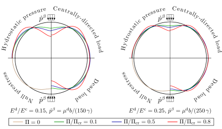
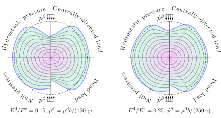
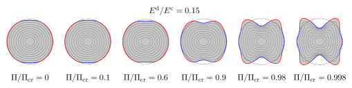
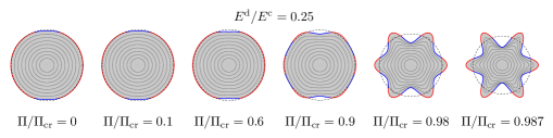
The external deformed shape of the coated disk is reported in Figs. 2 and 3, for different values of prestress in the former case, at fixed prestress Π/Πcr=0.8ΠsubscriptΠcr0.8\Pi/\Pi_{\text{cr}}=0.8 in the latter, where the deformed inner circles are also reported (the colour is proportional to the intensity of the field). In both cases two values of the ratio Ed/Ecsuperscript𝐸dsuperscript𝐸cE^{\text{d}}/E^{\text{c}} are considered, namely Ed/Ecsuperscript𝐸dsuperscript𝐸cE^{\text{d}}/E^{\text{c}} equal 0.15 and 0.25.

Both figures show that the compressive prestress decreases the stiffness of the system, which tends to vanish when the prestress in the coating approaches the bifurcation Π/Πcr=1ΠsubscriptΠcr1\Pi/\Pi_{\text{cr}}=1. The reported examples are all compared for the same fraction of prestress compared to the critical value, so that the differences are due to the particular type of radial load. The latter strongly affects the incremental deformation and the shape of the incrementally deformed solid.

The incremental displacement at the centre of the coating (under the resultant F𝐹F of the applied incremental load) is reported in Fig. 4 as a function of the prestress Π/ΠcrΠsubscriptΠcr\Pi/\Pi_{\text{cr}}, including also the tensile case (negative values of ΠΠ\Pi). Results are given for Ed/Ec={0.15,0.25}superscript𝐸dsuperscript𝐸c0.150.25E^{\text{d}}/E^{\text{c}}=\{0.15,0.25\}.

Refer to caption
Figure 4: Incremental displacement (divided by R𝑅R and positive when towards the centre of the disk) of the point on the coating located under the resultant F𝐹F of the incremental load p˙βsuperscript˙𝑝𝛽\dot{p}^{\beta} (distributed on an arch γ=4𝛾superscript4\gamma=4^{\circ}) as a function of the prestress Π/ΠcrΠsubscriptΠcr\Pi/\Pi_{\text{cr}}, ranging from tensile (negative values) to compressive (positive values). The differently coloured curves refer to different types of radial loads, all providing the same prestress ratio Π/ΠcrΠsubscriptΠcr\Pi/\Pi_{\text{cr}} in the coating. The asymptote of the curves denotes the critical load for bifurcation.

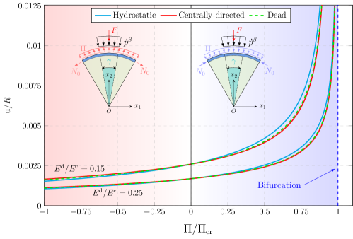
The figure shows that the first bifurcation load is obtained in a perturbative way, so that the critical load corresponds to the asymptote of the graphs. In particular, the critical bifurcation occurs at n=5𝑛5n=5 for Ed/Ec=0.15superscript𝐸dsuperscript𝐸c0.15E^{\text{d}}/E^{\text{c}}=0.15 and n=6𝑛6n=6 for Ed/Ec=0.25superscript𝐸dsuperscript𝐸c0.25E^{\text{d}}/E^{\text{c}}=0.25. The situation is detailed in Fig. 5, referred only to the case of hydrostatic pressure load. Here, at the increase of the prestress, the first bifurcation load is approached for both values of Ed/Ecsuperscript𝐸dsuperscript𝐸cE^{\text{d}}/E^{\text{c}}, but for Ed/Ec=0.25superscript𝐸dsuperscript𝐸c0.25E^{\text{d}}/E^{\text{c}}=0.25 the deformed mode approaches the bifurcation mode n=6𝑛6n=6, while in the other case the bifurcation mode is not correctly approached and the deformation remains symmetric, although n=5𝑛5n=5. However, in the latter case, when the bifurcation prestress is surpassed, the stiffness of the system becomes negative, thus showing that the critical load has been exceeded.

Refer to caption
Refer to caption
Figure 5: Incrementally deformed configurations of the coated disk for different ratios of Π/ΠcrΠsubscriptΠcr\Pi/\Pi_{\text{cr}} (from null prestress on the left to near-buckling pre-stress on the right) and for Ed/Ec=0.15superscript𝐸dsuperscript𝐸c0.15E^{\text{d}}/E^{\text{c}}=0.15 (upper part) and Ed/Ec=0.25superscript𝐸dsuperscript𝐸c0.25E^{\text{d}}/E^{\text{c}}=0.25 (lower part). The cases reported correspond to a pre-stress in the coating generated by hydrostatic pressure and the blue (red) colour highlights compressive (tensile) incremental tractions in the coating. Note that in the lower part, the bifurcation mode n=6𝑛6n=6 is approached, while in the upper part, the deformation remains symmetric even if the bifurcation mode is odd, n=5𝑛5n=5.

The level sets of the dimensionless von Mises stress inside the disk generated by the application of the incremental load are depicted in Fig. 6, for Ed/Ec=0.25superscript𝐸dsuperscript𝐸c0.25E^{\text{d}}/E^{\text{c}}=0.25 and two values of prestress (compressive Π/Πcr=0.5ΠsubscriptΠcr0.5\Pi/\Pi_{\text{cr}}=0.5 and tensile Π/Πcr=0.5ΠsubscriptΠcr0.5\Pi/\Pi_{\text{cr}}=-0.5).

Refer to caption
Refer to caption
Figure 6: Level sets for dimensionless von Mises stress inside a coated disk, induced by the application of the incremental load p˙βsuperscript˙𝑝𝛽\dot{p}^{\beta}, superimposed to a radial load producing the prestress in the coating. The prestress (compressive on the left and tensile on the right) in the coating is induced by different radial loadings. Results are compared to the case of the coated disk without prestressed for Ed/Ec=0.25superscript𝐸dsuperscript𝐸c0.25E^{\text{d}}/E^{\text{c}}=0.25. Note that the coating shields the stress inside the disk particularly when the prestress is tensile.

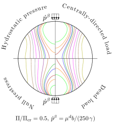
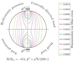
In the figure identical colours correspond to the same level of von Mises stress in all quadrants and for both figures on the right and the left. Results highlight the fact that a coating subject to tensile prestress produces a shield to the inner core, which is less stressed than in the case in which the prestress is absent.

5 Conclusions

States of prestress or residual stress in solids can originate from different sources, such as thermal mismatch, shrink-fit operations, but also external pre-loads, namely, loads already acting before any further increment of load is superimposed. The mentioned sources play an important role in the incremental behaviour of a solid, as shown in the present article through the investigation of the response of an elastic disk with prestressed coating, the latter modelled through an elastic circular (unshearable and inextensible) rod. Based on the main assumptions that the prestress state is negligible in the disk but affects the coating and that the latter is axially inextensible, an incremental solution, found analytically via complex potentials, has been proposed when the prestressed coated disk is subjected to an arbitrary incremental load distribution. The presented results show the importance of several effects related to: (i.) the type of radial load acting to generate the prestress before the incremental load is applied; (ii.) the interfacial conditions between coating and bulk solid; (iii.) the stiffening or weakening induced by prestress; (iv.) the possibility of approaching bifurcation loads and modes through a perturbative technique.

The use of stiff coatings is common in several man-made and natural systems, where interfacial conditions, type of loading, and state of prestress play an important role. The presented results may find applications in biomechanics and in the field of deformable solids used for mechanical actuation or load bearing.

Acknowledgements

The work has been developed in the framework of a NSF-ERC visit of S.M. (based in the United States) to the ERC project 101052956-Beyond, managed by D.B.. D.B. and M.G. gratefully acknowledge funding from the European Research Council (ERC) under the European Union’s Horizon 2020 research and innovation programme, Grant Agreement No. ERC-ADG-2021-101052956-BEYOND. A.P. gratefully acknowledges funding from the European Union (ERC CoG 2022, SFOAM, 101086644). S.M. gratefully acknowledges the support from the National Science Foundation, United States, award number NSF CMMI-2112894.

References

  • [1] Henrik M Jensen, John W Hutchinson and Kim Kyung-Suk “Decohesion of a cut prestressed film on a substrate” In International Journal of Solids and Structures 26.9-10 Elsevier, 1990, pp. 1099–1114
  • [2] IC Noyan and JB Cohen “Residual stresses in materials” In American Scientist 79.2 JSTOR, 1991, pp. 142–153
  • [3] JL Beuth Jr “Cracking of thin bonded films in residual tension” In International Journal of Solids and Structures 29.13 Elsevier, 1992, pp. 1657–1675
  • [4] O Jørgensen, A Horsewell, Bent F Sørensen and Peter Leisner “The cracking and spalling of multilayered chromium coatings” In Acta metallurgica et materialia 43.11 Elsevier, 1995, pp. 3991–4000
  • [5] Shu-guang Chen, Han-jun Gao, Qiong Wu, Zi-han Gao and Xin Zhou “Review on residual stresses in metal additive manufacturing: formation mechanisms, parameter dependencies, prediction and control approaches” In Journal of Materials Research and Technology 17 Elsevier, 2022, pp. 2950–2974
  • [6] Jay D Humphrey “Continuum biomechanics of soft biological tissues” In Proceedings of the Royal Society of London. Series A: Mathematical, Physical and Engineering Sciences 459.2029 The Royal Society, 2003, pp. 3–46
  • [7] Gerhard A Holzapfel and Ray W Ogden “Constitutive modelling of arteries” In Proceedings of the Royal Society A: Mathematical, Physical and Engineering Sciences 466.2118 The Royal Society Publishing, 2010, pp. 1551–1597
  • [8] Anne Hoger “On the residual stress possible in an elastic body with material symmetry” In Archive for Rational Mechanics and Analysis 88 Springer, 1985, pp. 271–289
  • [9] Anne Hoger “On the determination of residual stress in an elastic body” In Journal of Elasticity 16.3 Springer, 1986, pp. 303–324
  • [10] Anthony E Armenakas and G Herrmann “Vibrations of infinitely long cylindrical shells under initial stress” In AIAA journal 1.1, 1963, pp. 100–106
  • [11] Ray W Ogden and David J Steigmann “Plane strain dynamics of elastic solids with intrinsic boundary elasticity, with application to surface wave propagation” In Journal of the Mechanics and Physics of Solids 50 Elsevier, 2002, pp. 1869–1896
  • [12] Chi-Sing Man and WY Lu “Towards an acoustoelastic theory for measurement of residual stress” In Journal of elasticity 17.2 Springer, 1987, pp. 159–182
  • [13] Massimiliano Gei “Elastic waves guided by a material interface” In European Journal of Mechanics 27 Elsevier, 2008, pp. 328–345
  • [14] Moniba Shams, Michel Destrade and Ray W Ogden “Initial stresses in elastic solids: constitutive laws and acoustoelasticity” In Wave Motion 48.7 Elsevier, 2011, pp. 552–567
  • [15] José Merodio, Ray W Ogden and Javier Rodríguez “The influence of residual stress on finite deformation elastic response” In International Journal of Non-Linear Mechanics 56 Elsevier, 2013, pp. 43–49
  • [16] M Gaibotti, SG Mogilevskaya, A Piccolroaz and D Bigoni “Bifurcations of an elastic disc coated with an elastic inextensible rod” In Proceedings of the Royal Society A 480.2281 The Royal Society, 2024, pp. 20230491
  • [17] Davide Bigoni, Massimiliano Gei and AB Movchan “Dynamics of a prestressed stiff layer on an elastic half space: filtering and band gap characteristics of periodic structural models derived from long-wave asymptotics” In Journal of the Mechanics and Physics of Solids 56.7 Elsevier, 2008, pp. 2494–2520
  • [18] Zongxi Cai and Yibin Fu “Exact and asymptotic stability analyses of a coated elastic half-space” In International journal of solids and structures 37.22 Elsevier, 2000, pp. 3101–3119
  • [19] Massimiliano Gei and RW Ogden “Vibration of a surface-coated elastic block subject to bending” In Mathematics and Mechanics of Solids 7.6 Sage Publications Sage CA: Thousand Oaks, CA, 2002, pp. 607–628
  • [20] R.W. Ogden, D. Steigmann and D. Haughton “The effect of elastic surface coating on the finite deformation and bifurcation of a pressurized circular annulus” In Journal of elasticity 47 Elsevier, 1997, pp. 121–145
  • [21] Matteo Gaibotti, Davide Bigoni and Sofia G. Mogilevskaya “Elastic disk with isoperimetric Cosserat coating” In European Journal of Mechanics - A/Solids, 2022, pp. 104568 DOI: https://doi.org/10.1016/j.euromechsol.2022.104568
  • [22] Sofia G Mogilevskaya, Anna Y Zemlyanova and Mattia Zammarchi “On the elastic far-field response of a two-dimensional coated circular inhomogeneity: Analysis and applications” In International Journal of Solids and Structures 130 Elsevier, 2018, pp. 199–210
  • [23] N.I. Muskhelishvili “Some basic problems of the mathematical theory of elasticity” Springer Science & Business Media, 1959
  • [24] A.Y. Zemlyanova and S.G Mogilevskaya “Circular inhomogeneity with Steigmann–Ogden interface: Local fields, neutrality, and Maxwell’s type approximation formula” In International Journal of Solids and Structures 135 Elsevier, 2018, pp. 85–98
  • [25] Sofia G Mogilevskaya, Steven L Crouch and Henryk K Stolarski “Multiple interacting circular nano-inhomogeneities with surface/interface effects” In Journal of the Mechanics and Physics of Solids 56.6 Elsevier, 2008, pp. 2298–2327
  • [26] J Singer and CD Babcock “On the buckling of rings under constant directional and centrally directed pressure” In Journal of Applied Mechanics, 1970