Passive Non-line-of-sight imaging of moving targets using Physical embedding and Event-based vision
Abstract
Passive Non-line-of-sight (NLOS) imaging has shown promising applications in imaging occluded objects around corners. However, this inverse problem is highly ill-posed and results in poor reconstruction with traditional physical retrieval methods, particularly in moving target imaging. With the development of neural networks, data-driven methods have greatly improved accuracy, however, heavy reliance on data volume has put great pressure on data collection and dataset fabrication. We propose a physical embedded passive NLOS imaging prototype with event-based vision (PNPE), which induces an event camera for feature extraction of dynamic diffusion spot and leverages simulation dataset to pre-train the physical embedded model before fine-tuning with limited real-shot data. The proposed PNPE is verified by simulation and real-world experiments, and the comparisons of data paradigms also validate the superiority of event-based vision in passive NLOS imaging for moving targets.
1 Introduction
Non-line-of-sight (NLOS) imaging, as a reconstruction and detection technique for hidden objects outside the direct line-of-sight, has shown promising potential for applications in medical imaging, autonomous driving, reconnaissance and rescues [1, 2, 3, 4].
In some review articles [3, 5], NLOS imaging can be classified into active and passive NLOS imaging, depending on whether a controllable light source is used. Active NLOS imaging [5] primarily adopts a pulsed laser as active probing source and acquires three-bounce photon information to reconstruct hidden targets. In passive NLOS imaging [5], diffuse reflection on the relay wall is captured and analyzed by data mining with physical priors. Therefore, the forward models of these two types of NLOS imaging are completely different.
Thanks to the prosperous evolutions of novel sensors and imaging devices, we have witnessed rapid development in active NLOS imaging over the past decade. Leveraging the high sensitivity of single photon avalanche diodes (SPAD) in single-photon detection and counting [6], high time resolution is achieved for ultra-fast photography and probing [7]. According to whether the time parameter of light transport is sampled at sub-picosecond scales by the camera, imaging can be classified as transient imaging [8, 9, 10] and steady imaging [11]. Most active NLOS imaging employs transient information and realizes depth reconstructions for occluded targets by decoding the time-of-flight (TOF) information adopted by the “three-bounce” photon-counting histogram [12, 13]. Different algorithms have been proposed to interpret the NLOS light field [14], such as back projection (BP) [15], light-cone transform (LCT) [16], compressed sensing (CS) [17], and fk-migration [18] for photon-counting data processing, which show satisfactory reconstruction results. However, active NLOS system requires precise calibration [19, 20] and performs repeated scanning, which is time consuming and suffers from perturbation. Moreover, light field interpretation requires sophisticated algorithms and significant computational resources, making real-time applications [21] challenging and potentially limiting the practicality in certain scenarios especially dynamic scenes.
In contrast, passive NLOS imaging mainly falls in the field of steady imaging [11], which has shown promising application potential owing to its simple system and efficient data acquisition in ordinary imaging circumstances [22]. In this paper, we mainly focus on this type of simplified and environmentally flexible imaging method. In steady-state imaging, a commonly used pipeline is to employ a flat-panel detector to capture the diffuse reflection information on the relay surface [23], and reconstruct the hidden object with frame-based intensity information [24]. With the development of computational imaging [25] and passive NLOS imaging, different dimensions of diffuse reflection observations are proposed to handle certain scenarios, such as phase retrieval [22, 26] based on traditional intensity structures [23, 24, 26, 27], polarized ques [28], optical TOF techniques [29], thermal methods [30] and spectral content approaches [31]. However, limited by the camera shutter speed, these types of frame-based information of different light field dimensions cannot be temporally resolved, which implies that different depths and textures of object information are interleaved within the integrated time of each snapshot. In particular, for NLOS moving target imaging [20, 32, 33, 34], the frame-based passive NLOS detection mode suffers more from serious degradation on the relay surface and superposition disturbance from isotropic diffuse reflection in close pixels. Towards this end, we introduce event camera [35] for passive NLOS sensing, which captures spatio-temporal information with its asynchronous sampling paradigm. Consequently, we can establish an inverse problem based on the single reflection forward model, where optimization algorithms are prompted [36] for a better solution.
For the reconstruction of passive NLOS imaging, we trace back to the original intention of computational imaging. The essence of computational imaging is to retrieve information or features with limited projections of the physical light field captured by the sensor [37]. Since original frame-based intensity data act as low dimensional acquisitions, the condition number of the ill-posed problem is enlarged. Therefore, current research on passive NLOS mainly focuses on reconstructing the object shape or positioning by mining the diffuse information on the relay surface and optimizing the blind deconvolution using data-driven approaches [38, 39, 40]. Moreover, without guidance from physical mechanisms, the generalization ability of the deep learning model depends heavily on data diversity and volume. Consequently, some physical embedded data-driven methods [41, 42] have emerged to alleviate this dilemma, but the demand for data volume imposes significant pressure on data collection and dataset fabrication. Nevertheless, these end-to-end deep learning approaches [11, 17] only perform well in static NLOS imaging [18], but show shortcomings in moving target reconstructions due to the superposition of dynamic diffuse reflection. Leveraging the sensitivity of event cameras in dynamic vision and feature extraction [43], we establish an event-based and physics-informed passive NLOS imaging framework for moving targets to put forward its applications in practical scenarios.
In this work, we propose a passive NLOS computational imaging framework, termed “Passive Non-line-of-sight imaging of moving targets using Physical embedding and Event-based vision” (PNPE), which improves the NLOS imaging performance of moving targets with the physical priories supported by simulation datasets. In PNPE prototype, we train the end-to-end(E2E) network on large simulation datasets and fine-tune the model with small real-shot datasets. With the instruction of the pre-trained model, more dynamic light field propagation parameters are included, which embeds physical transportation mechanics and priors to enhance the reconstruction ability. The main contributions of this study can be summarized as follows.
-
•
The introduction of event-based vision to NLOS imaging enables in-sensor computing for feature extraction in dynamic light field, opening up new possibilities for moving object reconstruction in NLOS.
-
•
The physical embedded data-driven method under PNPE framework provides a new gateway for passive NLOS imaging using limited real-world dataset.
-
•
The fusion of event stream with intensity information further improves the reconstruction performance in dynamic NLOS scenes.
2 Principles and Methodology
In this section, we introduce the data acquisition principle of event-based cameras and review the event-paradigm forward model in passive NLOS for further simulation prototype establishment.
2.1 Event-based Vision
Event cameras, also known as bio-inspired neuromorphic vision sensors, are a type of image sensing devices that respons significantly different from traditional frame-based cameras [35]. Instead of capturing the absolute brightness of the full frame at fixed intervals, event cameras detect and report per-pixel brightness changes asynchronously and in real-time. The novel sampling paradigm brings extraordinary sensitivity to dynamics for event cameras, which results in high temporal resolution, high dynamic range, and low latency. Therefore, event-based vision has significantly broadened various applications in challenging scenarios for traditional cameras, encompassing diverse applications in high dynamic range high speed imaging [44], robotics, autonomous vehicles [45] and object detection [46] in sophisticated optical field.
The sampling principle of an event camera is illustrated in Figure 1. When the pixel-wise logarithmic intensity of brightness changes exceeds the pre-set threshold, the specific pixel is triggered and an event is recorded binomially, either positive or negative. Each pixel continuously monitors the logarithmic form of the intensity, awaiting sufficient amplitude changes to fire another event.
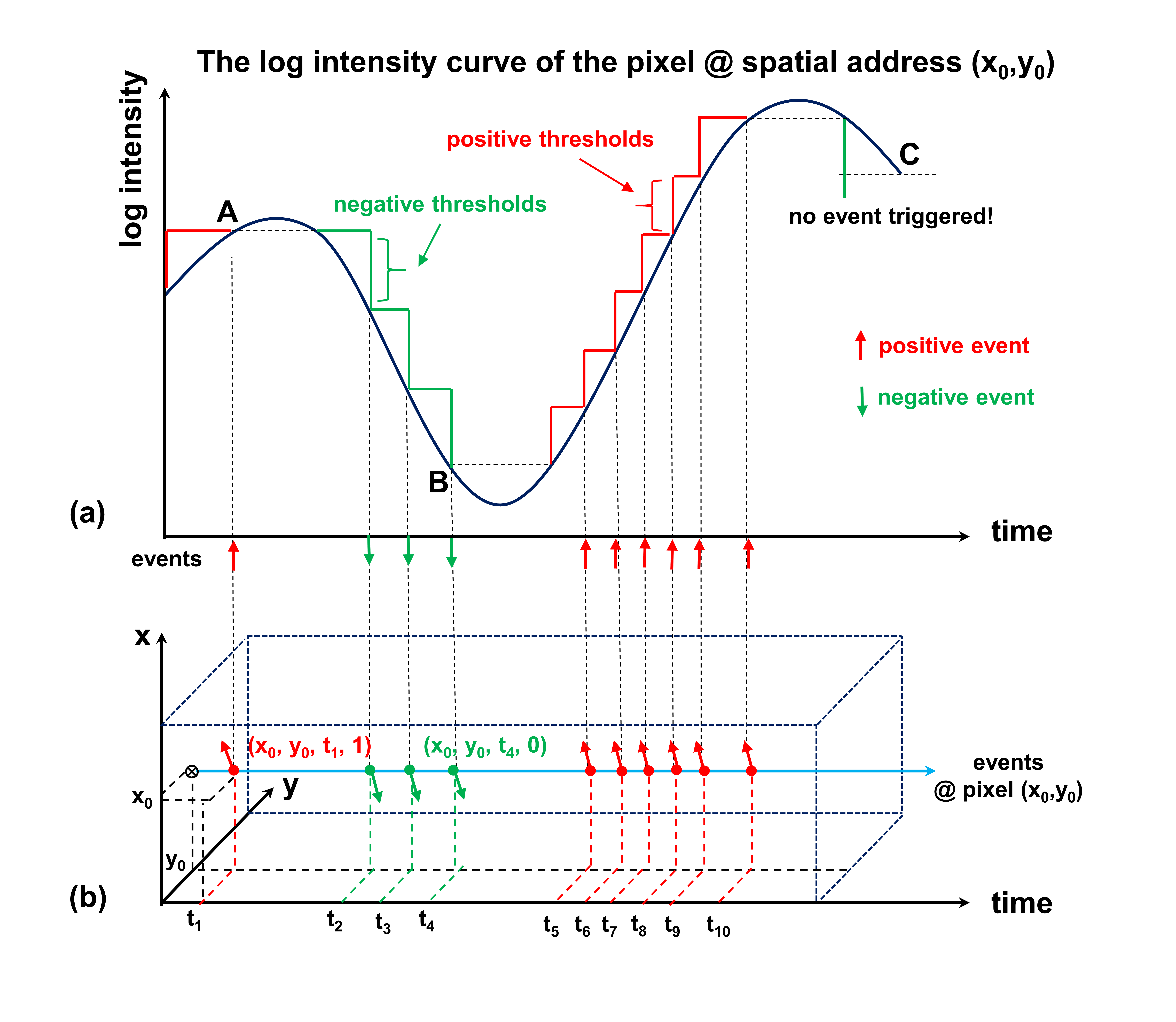
As shown in Figure 1(a), a positive event is triggered at point A and a negative event at point B, whereas no event is triggered at point C since the change in intensity does not reach the pre-set threshold controlled by the bias voltage. Additionally, the 4-dimensional event data can be represented by a set of sparse scatter points in the spatio-temporal cube in Figure 1(b), which intuitively expresses the property of event excitation.
An event is characterized by four distinct parameters: spatial address x, y, time stamp t, and polarity p, which is noted as for the event,
| (1) |
where x and y denote the spatial address of the fired pixel, t records the time stamp of the triggered time, p represents the binary polarity flag indicating an increase or decrease in brightness, respectively.
2.2 Forward Model of Passive NLOS imaging
The forward model of passive NLOS imaging [27, 47] plays a crucial role in explaining how light is transported in hidden scenes and how it is captured and interpreted by the sensor for reconstruction. It forms the physical foundation for developing algorithms and techniques to improve the reconstruction quality of passive NLOS imaging.
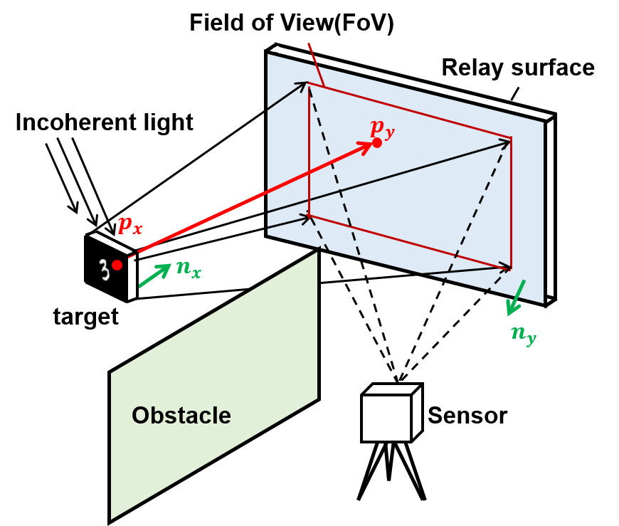
In particular passive NLOS setups, we express the forward model by describing the light field mapping relation between the hidden object and the diffusely reflecting surface, which is known as relay surface. Specifically, as shown in Figure 2, the irradiance of a patch at on the relay surface [27] can be expressed as
| (2) |
where demotes the source irradiance emitted from the hidden target, demotes the irradiance distribution on the relay surface, stands for the whole source pixels corresponding to the detecting field of view (FoV) and represents the background noise term including ambient light noise and detection noise. Taking the geometric relationships of light field propagation into consideration, explicates the point-to-point transmission weighting for different position relationships [27], which is specified as
| (3) |
where and depict the angle between the transmission vector formed by mapped pixel pair and hidden object with the normal vector on each of their surface plane, respectively, as shown in Figure 2 (a). The coefficient represents the bidirectional reflectance distribution function (BRDF), parameterizing the reflective properties of different areas on the relay surface, which is regarded as a constant in this study when the relay surface can be approximately modeled as an isotropic diffusely reflecting surface. The cosine form of these two angles endures weights for optical transmission, reflecting the relative brightness and visual angle of different points in the scene and at different positions on the relay surface. In addition, the Euclidean norm in the denominator is utilized to characterize attenuation with range.
When substituting Eq. 3 into Eq. 2, we summarize the forward model of passive NLOS imaging, and establish a simplified discrete version of the detection function on the relay surface which outlines the physical mechanism and suitable for further simulation at the same time.
| (4) |
where h denotes the point spread function (PSF) of the entire transmission system. However, h is difficult to express analytically by linear functions directly because the propagation process and the diffuse reflection on the relay surface make the system a spatially variant system. Furthermore, when imaging and sensing moving objects, the light field information will also superpose in time domain, increasing the ill-posedness and creating more difficulties for the simulation.
Fortunately, the pixel-wise convolution form is similar to the diffraction of light field, where each pixel on the detection plane interacts with each equivalent light source pixel on the object plane. Inspired by the wave-based method proposed by X. Liu et al. [14], we assume the illuminated target as several secondary point sources and the detecting FoV on the relay surface as vitual sensor array so that the pixel to pixel transmission process can be split into Rayleigh-Sommefeld Diffraction (RSD) propagation and interaction with the relay surface.
We utilize the angular spectrum form of RSD to model and calculate the propagation process, which supplies the linear portion. Then, we adopt random scattering theory to demonstrate the diffusely reflection, conducting the non linearity and interactional effects. These two sequential processes are expressed by PSF and transmission function (TF), as shown in Eq. 5.
| (5) |
where represents the PSF of RSD and represents the interaction function with the relay surface. Specifically, a simplified discrete version of Eq. 5 can be written in matrix form as:
| (6) |
where D and S act as the transmission matrix of RSD and diffuse reflection, respectively, , y denotes the measurement and x stands for hidden scene.
Usually, based on the forward model, the corresponding inverse problem can be transformed into an optimization problem for better restoration,
| (7) |
where is the regularizer.
2.3 Event paradigm representations and reconstructions in passive NLOS
With the superiority in dynamic information sensing, event cameras are widely used in robotics, computational photography, and vision tasks especially in challenging environments. In this study, we introduce an event representation method to excavate event-based data and extract spatio-temporal features from dynamic diffusion spots, which contain efficient information of the target movement.
Compared with traditional direct-view imaging, when processing NLOS dynamic scenes, the movement of hidden targets raises additional spatio-temporal aliasing for passive NLOS imaging, increasing the blindness and difficulty of inverse restoration. The challenge of passive NLOS imaging for moving targets is the acquisition of dynamic information of diffusion spots without distortion, and how to extract dynamic features from the captures for better reconstruction. In this work, event-based vision is proposed to mitigate aliasing and extract more efficient movement information as well as the spatio-temporal texture feature of the diffusion spot on the relay surface. However, the sparse asynchronous paradigm of event data is not applicable for direct substitution in the forward model of passive NLOS. Therefore, event-based representations must be implemented for information dimension conversion and a more efficient dynamic feature expression.
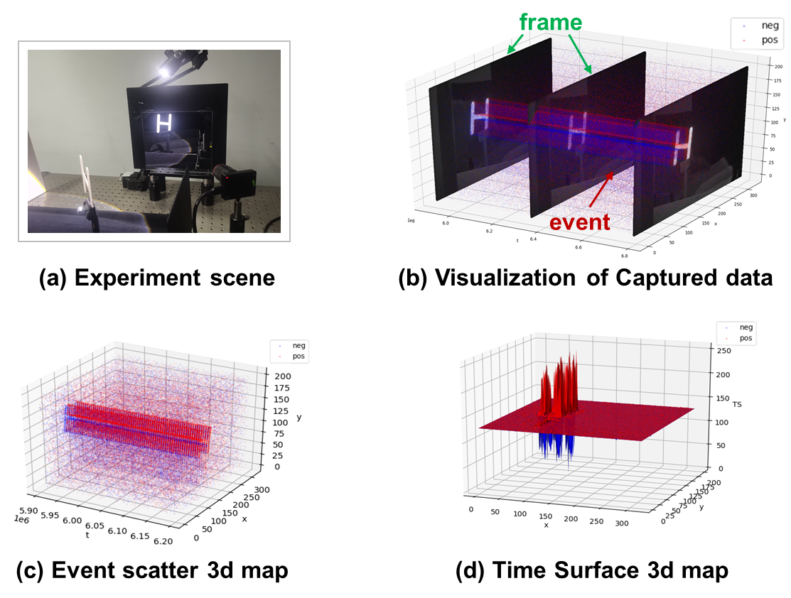
We demonstrate event-based representation [48, 49] by visualizing a set of real-shot event data. For an intuitive illustration, we temporarily use a mirror as the relay surface, and the hidden target “H” moves from left to right in the camera FoV. The difference in data format between event-based and frame-based data is visualized in Figure 3 (b), where the event-based paradigm can record inter-frame dynamic information. As shown in Figure 3 (c), the asynchronous captured events are represented by scatter points in 3-dimensional cuboid, representing distinct parameters x, y, and t, whereas the color represents polarity. To extract spatial and temporal feature from event data and convert into a suitable format for the forward model, we perform Time-surface (TS) calculation on the selected voxel grid [49] and obtain the TS value according to the polarity, as shown in Figure 3 (d). The TS value expresses both temporal and spatial correlations of events in the time interval of the selected voxel grid, which can be specified as:
| (8) |
where denotes the TS value of event , in which the exponential kernel supplies the decay of spatial and temporal relevance with other event points within the spatial neighborhood . The normalized context time stamp , represents the time-context standard for all events whose spatial address falls in the neighborhood within radius from the incoming , defined as Eq. 9.
| (9) |
where and demotes the spatial address vectors of event and . plays an important role in determining the temporal center of the event points involved in calculation, and , are the polarity and time constant, respectively.
Based on the representation of event data, we summarize the event form forward model of passive NLOS in our previous study [43]. In addition, to provide a matrix-like mathematical expression, we divide the event data into several time voxel grids [49], and calculate the TS map on each voxel grid to substitute the measurement matrix in Eq. 6. By defining the element-wise intensity of pixel i at the center timestamps and in two adjacent voxel grids as and , the event form detection function can be written by the pixel-wise intensity difference as:
| (10) |
where demotes the time interval of a voxel grid, and the limitation form explicits the accumulation of target intensity changes at each pixel, annotated as , which contains the movement information of the target during interval . In addition, the sampling paradigm of event cameras can effectively eliminate ambient noise so that only sensor noise remains, .
We can then rewrite the forward model by analytically substituting TS calculation into the detection function as Eq. 6. Before performing TS calculation to obtain the featured map, we define a discrimination function to indicate whether an event is triggered.
| (11) |
where and are the preset triggered threshold for positive event and negative event respectively.
Then, TS calculation is performed in a set of voxel grids, the context information of movements is accumulated, and the spatio-temporal features of the moving target are concised into a matrix ,
| (12) |
where denotes TS calculation, and all triggered events in the FoV on the relay surface contribute to the . The 2d matrix form is the projection of TS 3d map on plane, in which the passive and negative maps are normalized in one matrix.
Therefore, the event form forward model is written as,
| (13) |
According to the reconstruction methods from event data to images [44], the relationship between the absolute intensity and target movement conveyed by the TS map can be bridged as an implicit function, i.e. . Thus, Eq. 13 is converted to a function with respect to the hidden scene x,
| (14) |
where is the adapted transmission matrix, with a relatively large condition number, i.e. . Typically, the reconstruction problem of event-based NLOS is transformed into solving the inverse problem described by Eq. 14, which retrievals the hidden target by solving the optimization problem,
| (15) |
where J denotes the priori induced by the physical transmission process and event-based feature representation.
3 Passive Non-line-of-sight imaging of moving targets using Physical embedding and Event-based vision
In this section, we propose a novel framework for enhancing passive NLOS imaging of moving targets, which compensates for the shortcomings of end-to-end (E2E) reconstructions. The event-based detecting paradigm enhances the perception capabilities of the dynamic light field, whereas the simulated pre-training method is used to better illustrate and embed the physical forward transmission characteristics.
3.1 PNPE Prototype
Recall that the spatio-temporal feature of the hidden target movements can be expressed by the TS map of diffusion spot movements on the relay surface, and the event paradigm NLOS forward model is consistent with the traditional frame-based one, we performed an E2E deep learning method to optimize the retrieval process in our previous work [43]. To further improve the reconstruction quality, we need to overcome the over-fitting and strong reliance on data distribution introduced by data-driven approaches. However, the data acquisition process for illuminated objects makes it difficult to fabricate data sets with large data volumes and rich diversity.
To the best of our knowledge, we firstly propose the "Passive Non-line-of-sight imaging of moving targets using Physical embedding and Event-based vision" (PNPE) prototype to establish large simulation datasets for pre-training the physical embedded model, and fine-tune with limited real-shot data. The PNPE prototype acts as a Plug and Play (PnP) structure, which combines the shared physical mechanism of forward transmission in passive NLOS, and allows the adjustment in real-world captures for both frame-based and event-based vision.
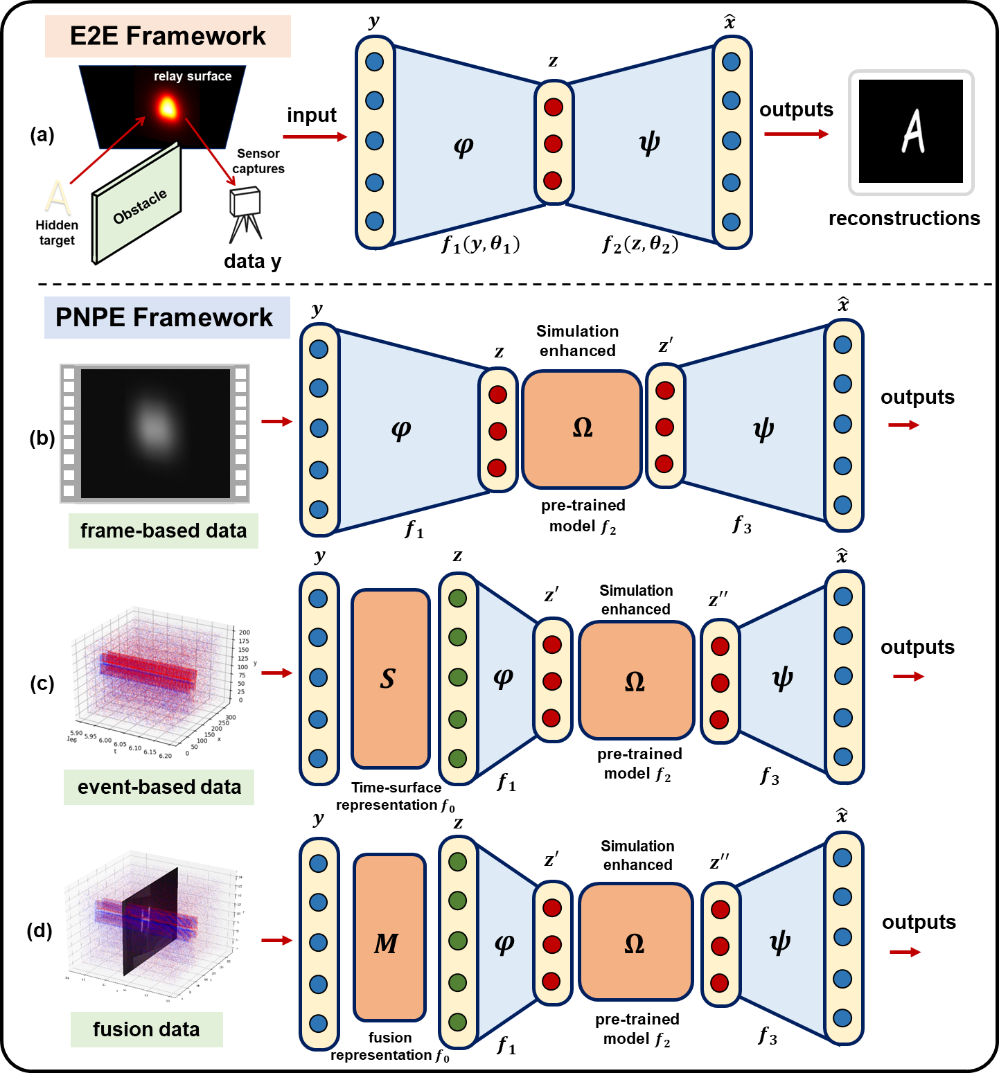
As shown in Figure 4, based on the forward model, traditional E2E reconstruction with data-driven method is illustrated in Figure 4 (a), where the sensor captures pass through the encoder and decoder successively for feature extraction in the latent space and reconstructions. The loss function is crafted to optimize the parameters in mapping relations and . In this case, the physical fundamentals are implicitly modeled and concealed in data-driven network models. To maximize the effect of physical embedding in guiding the convergence of data-driven network, we propose the PNPE prototype as shown in Figure 4 (b)(c)(d), which adapts different paradigms of the input data: event, frame and fusion forms. The frame-based PNPE framework embeds the pre-trained simulation-enhanced module in the latent space to instruct the training when fine-tuned using real-shot data. Similarly, the event-based counterpart adopts an additional TS representation module to convert the data format. In addition, the fusion form is the combination of a frame-based snapshot with event-based data in voxel grids within a certain time interval, which requires a fusion representation module before the simulation-enhanced module .
Specifically, we curate the data by simulating large-scale data sets for passive NLOS of moving targets, i.e. captures of the dynamic diffusion spot intensity information on the relay surface. Then, we train the E2E model with simulation datasets to learn the physical light field transmission mechanism as a pre-trained model. Thus, when limited real-shot datasets are input to the corresponding framework, simulation-enhanced module supplies physical constraints and priors to alleviate the over-fitting caused by insufficient data diversity and further enhance the reconstruction performance.
3.2 Simulation Pipeline
The simulation pipeline for passive NLOS imaging of moving targets in our PNPE prototype can be divided into three main steps as shown in Figure 5.
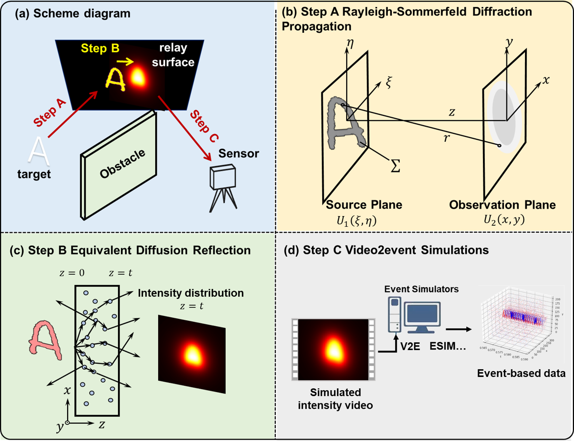
3.2.1 Step A: Rayleigh-Sommerfeld Diffraction Propagation
Recall that the propagation of light field is expressed by discrete convolution in Eq.6, diffraction integral is an accurate way to describe this process in numerical simulations.
Assuming that the illuminated hidden object can be modeled as a set of secondary point sources, we utilize Rayleigh-Sommerfeld diffraction (RSD) [50] to simulate the forward propagation of the light field emitted from the target before it arrives at the relay surface.
Since the temporal phase information is lost with passive NLOS detection, we slightly modify the RSD-based Virtual Wave Optics [14] to fit the forward model, as shown in Figure 5 (b). Suppose the intensity distribution of the hidden object is written as , the light field before hitting the relay surface is calculated by Eq. 16.
| (16) |
To expedite the calculation, we adopt the angular spectrum form of RSD to calculate the propagation process. Specifically, we approximate the propagation as plane to plane diffraction, rewrite the integral with planar primitives, and get the expression of complex amplitude as Eq. 17.
| (17) |
where is the angular spectrum, and is the spatial frequency, and and are the angles formed by wave vector and the corresponding axis. The first exponential factor serves as the transmission function .
Finally, we take the norm of matrix and obtain the intensity distribution of light field before interacting with the relay surface.
3.2.2 Step B: Equivalent Diffusion Reflection
For a long time, the modeling of random scattering on relay surface has been a bottleneck in NLOS simulations. In this work, we do not pursue exactly accurate modeling of the diffusely reflection properties of the relay surface, but statistically construct the distribution of the light field after the interaction with relay surface.
Since imaging through scattering layers and imaging around corners shares similar diffraction-limited optical imaging system, the imaging technique can be interchanged to some extent, for example via speckle correlations [26]. The physical mechanism of imaging through scattering medium can also be applied to imaging occluded targets in NLOS area using the light back-scattered from a diffusive surface. Therefore, with assuming the reflection from the relay surface to be Lambertian, we can use scattering theory to equivalently simulate diffusely reflection in “around the corner” circumstance [26].
As shown in Figure 5 (c), we leverage the random walk and diffusion-like model of photons [51] to statistically simulate the photon’s behavior and pattern when interacting with the diffuse surface. Therefore, the possibility distribution of photons on the relay surface after interaction can be approximately expressed by the transmission point spread function (tPSF) of turbid media [52, 53] as Eq. 18.
| (18) |
where denotes the lateral distance from the start point of random walk, is the ratio of slab thickness to scattering mean free path . We simulate the tPSF curve when the equivalent thickness is set to unit 1, and normalize the calculation result for demonstration, as shown in Figure 6 (a).
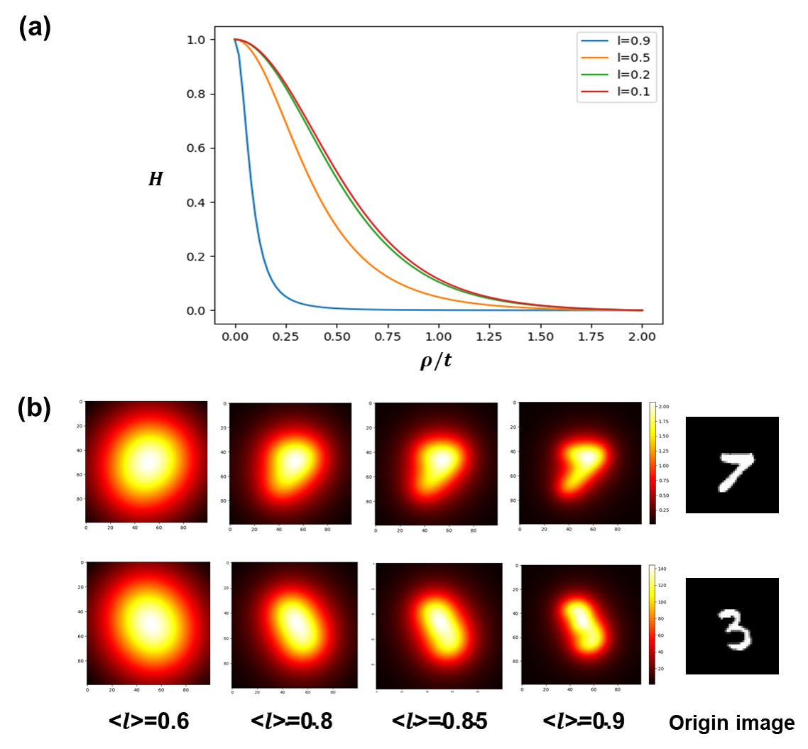
The trend of the curve is very similar to that obtained from Lambert’s Cosine Law, which indicates the feasibility of simulated diffusion approximation with multiple-path random walk model through turbid media.
After performing convolution to the incidence image with kernel formed by , the simulation results under different scattering mean free path are shown in Figure 6 (b). It is obvious that the larger indicates less step in random walk, which results in sharper trend of the curve. The broadening of the curve on the describes the effect of diffuse dispersion. We select , ,and sampling from 0 to 2 with 100 discrete points uniformly for simulation.
3.2.3 Step C: Video2event Simulations
After simulating of RSD propagation and diffuse reflection, frame-based datasets are ready to be generated when random noise is added. However, to simulate the event-based captures for movement feature extraction, we need to transfer the intensity distribution into event paradigm. As for this paradigm conversion, we generate a video with simulated intensity distribution at different moment through the object movement, and use the start-of-the-art event flow simulation pipeline video2event (v2e) [54] to simulate the event-based acquisitions, as shown in Figure 5 (d). The v2e simulation is conducted with parameters listed in Table 1.
| parameter | value | symbolic unit |
|---|---|---|
| timestamp resolution | s | |
| dvs exposure duration | s | |
| positive threshold | - | |
| negative threshold | - | |
| sigma threshold | - | |
| wight,hight | pixel | |
| cutoff hz | Hz | |
| shot noise rate hz | Hz | |
| model | SuperSloMo39.ckpt | - |
where the timestamp resolution sets the up sampling factor for the input video. It can be combined with the “Slow motion” model that can interpolate frames to ensure DVS events reach at most resolution. The dvs exposure time supplies the fixed accumulation time for event camera to finish the frame event integration. The positive and negative thresholds show the logarithmic form of the intensity change to trigger a corresponding event, and the sigma threshold controls the deviation threshold variation of the logarithmic intensity change. The cutoff frequency and shot noise rate are control parameters of the sensor circuit, where the cutoff frequency is responsible for photoreceptor infinite impulse response low-pass filter, and the shot noise rate determines the temporal noise rate of ON and OFF events.
3.3 Reconstructions with PNPE
In the last step of solving the inverse problem in NLOS reconstruction, we adopt a UNet as the backbone structure, using skip connection to perform multi-scale feature fusion, and add a residual block to avoid gradient explosion during training.
We design adaptive data loaders for three different paradigms of data, as shown in Figure 4. Screenshots of the diffusion spot and event TS maps are loaded directly as 2d image form to the network, serving as the frame-based intensity data and event-based feature map. It’s worth noting that the fusion form is the combination of frame-based image and even-based TS map, which is loaded as a concatenated tensor.
For the pre-training session, we trained our model on the simulation training set of each data paradigm with an adaptive moment (Adam) estimation optimizer for 200 epochs. For the enhanced reconstruction session, we load the pre-trained model with the test set of each data format, and fine-tune the model for approximately 100 epochs before sending it through the decoder for reconstructions.
To conclude, The event-based sampling paradigm together with the PNPE framework provides a fast and effective gateway for passive NLOS imaging of moving objects.
4 Experiments and Results
As proof of concept, we demonstrate the performance of PNPE prototype through simulation and real-shot experiments.
4.1 Experimental settings
The experimental settings are shown in Figure 7, an illuminated target ‘A’ is moving from left to right under indoor ambient light, controlled by a motorized translation platform and blocked by the obstacle.
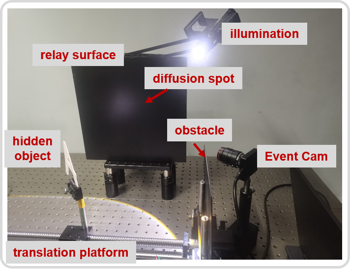
The targets used in the real-world experiment are fabricated by laser printing acrylic material in the shape of alphabet ‘A-Z’ and number ‘0-9’ in Comic font, with a size of , which translates at a speed of 2cm per second. A frosted aluminum fender is used as the relay surface, which provides homogeneous scattering, and the moving target is placed about 40 cm from the fender. We use a torch to illuminate the hidden target and use an event camera (CeleX V-MIPI) to record the moving diffusion spot on the relay surface. Event-based data and frame-based data are acquired with different modes of the CeleX camera. Specifically, we obtain the event stream data in event-intensity (EI) mode and get frame series at a frame rate of 100 frames per second in full-picture (F) mode, which recorded the dynamic diffusion spot corresponding to the movement of the hidden object.
4.2 Simulation experiments and results
To evaluate the performance and effectiveness of our proposed PNPE framework, simulation experiments are conducted to pre-train the physical embedded model and verify the enhancement with event-based vision.
First, we perform simulations according to the forward model and corresponding experimental settings.The simulation pipeline of generating the light field on the relay surface is illustrated in Figure 8.
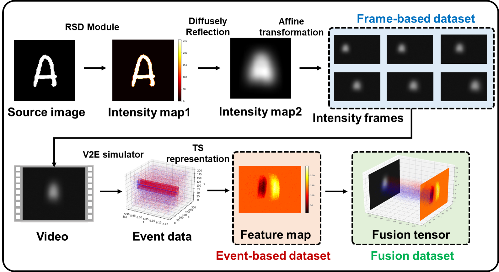
Based on the source image including alphabet characters selected from the NIST dataset [55] and hand-crafted comic digits, we generate the intensity distribution of diffusion spots on the relay surface at different positions with the target movement. The simulation process for the fundamental frame-based dataset is conducted through RSD module, diffusely reflection simulation, and affine transformation.
Specifically, in RSD module, we set the diffraction propagation distance as 500 mm, the center wavelength as 500 nm and perform RSD simulation by convoluting with the transfer function in the form of angular spectrum. Similarly, in simulation of diffusely reflection, we adopt the equivalent tPSF calculated with parameter value , and generate the intensity distribution after interacting with the relay surface by convolution. Affine transformation operations are performed to consider the geometric relationships between sensor and its FoV. Moreover, random noise and gain factors are also included in the simulation.
After obtaining the frame-based dataset, the event-based and fusion datasets are established consecutively. We use the V2E simulator to generate event data from the videos synthesized from simulated intensity frames, perform TS calculation for dynamic feature extraction, and obtain the TS feature map as event-based dataset. For fusion dataset, we concatenate the TS map with intensity frame corresponding to the concerned event data, and save it as a tensor. The generated simulation datasets are presented in Table 2,
| train & validation | test |
|---|---|
| NIST letters | NIST letters |
| Comic letters | |
| Comic nums |
where the training set contains 1014 different types of alphabet character in the NIST dataset [55], and the testing set include 26 letters each from the NIST and Comic dataset. The number ‘40’ in brackets indicates that we generate data at 40 equidistant positions through target movement.
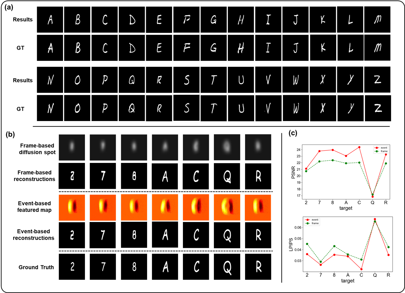
Finally, with the prepared simulation data sets, we conduct simulation experiments by comparing the event-based and frame-based reconstructions, as shown in Figure 9.
We train the simulated training set with a UNet structure utilizing an adaptive moment (Adam) estimation optimizer implemented on PyTorch 1.7.0 with an Nvidia RTX 3090 GPU for 200 epochs. A learning rate of is used for the first 100 epochs, whereas it varies to for the remaining epochs, with batch size of 16. The loss function is crafted as a combination of Mean Absolute Error (MAE) and Structure Similarity Index Measure (SSIM):
| (19) |
where , denotes the reconstruction and ground truth, represents L1 loss. The weight factor of the SSIM loss is selected as 2 to balance these two components better.
Both the event-based and frame-based datasets are pre-trained, and the test results on the event-based simulated testing set (NIST) are shown in Figure 9 (a), which verifies the generalization of the pre-trained network.
The simulated testing set (Comic) is considered as another data distribution and is used to examine the transfer ability of physical embedding enhancement induced by the pre-trained model on a sufficient simulation dataset. We load the pre-trained model and the testing set (Comic) of frame-based and event-based formats into the framework, respectively, and fine-tune the model for 100 epochs with learning rate of and batch size of 16, implemented on same configurations. The test results are shown in Figure 9 (b), and the evaluation metrics of event-based and frame-based methods are compared in Figure 9 (c). We use peak signal to noise ratio (PSNR) and learned perceptual image patch similarity (LPIPS) [56] with a VGG core to assess the reconstruction quality. PSNR quantifies pixel-wise distortion, and LPIPS extracts features through neural networks and calculates feature differences for effective evaluation, which is more in line with human perception. It’s worth noting that a lower LPIPS indicates better reconstructions, which is different from traditional evaluation indices such as PSNR.
It can be seen from the test results that event-based vision performs better than its frame-based counterpart when using the PNPE prototype to fine-tune and transfer between different data distributions, especially the reconstructions of Comic numbers.
4.3 Real-shot experiments and results
For the experimental proof of the ENPE prototype, we construct the experimental setup, as shown in Figure 7. Real world experiments are conducted to validate the superiority of the PNPE prototype compared with E2E data-driven method.
We use an event camera to record the moving diffusion spot on the relay surface in event-based mode (EI) and frame-based mode (F) respectively. The collected data under the EI and F modes are converted into real-shot datasets after calibration to the ground truth by the initial time stamp. The targets we used are flat acrylic characters of alphabet letters and numbers in Comic font. The distance between the target and relay surface are set as 30 cm (near) and 50 cm (far) for two sets of experiments, to validate the robustness.
To the best of our knowledge, we firstly establish the Comic-NLOS dataset, which contains 2880 images in each of the three data paradigms, i.e. frame, event and fusion. The fabrication process of the real-shot datasets of three data formats is the same as that of their simulation counterparts. The naming and composition of the datasets are listed in Table 3,
| Name | frame | event | fusion |
|---|---|---|---|
| Comic letters near | |||
| Comic nums near | |||
| Comic letters far | |||
| Comic nums far |
where the ’Comic letters’ dataset contains 26 alphabet characters, the ’Comic nums’ dataset contains 10 number digits, and the suffix of ‘near’ and ‘far’ supplies the distance from the target to relay surface. The captured data of each target are produced into 40 featured images, which represent the movement of the diffusion spot at different positions.
After adopting the pre-trained model on simulation dataset for physical embedding, we load the real-shot dataset for fine-tuning through the PNPE framework. The pre-trained model is trained on the simulated NIST dataset only, and we fine-tune the network with both Comic letters and Comic nums datasets of the three data paradigms. The test results of real-shot experiment using E2E data-driven method and PNPE framework are shown in Figure 10(a)(b), respectively, and the reconstructions of target movement at different positions with fusion format data through PNPE are demostrated in Figure. 10(c).
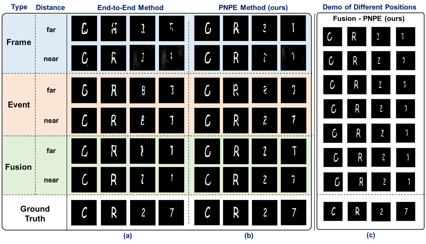
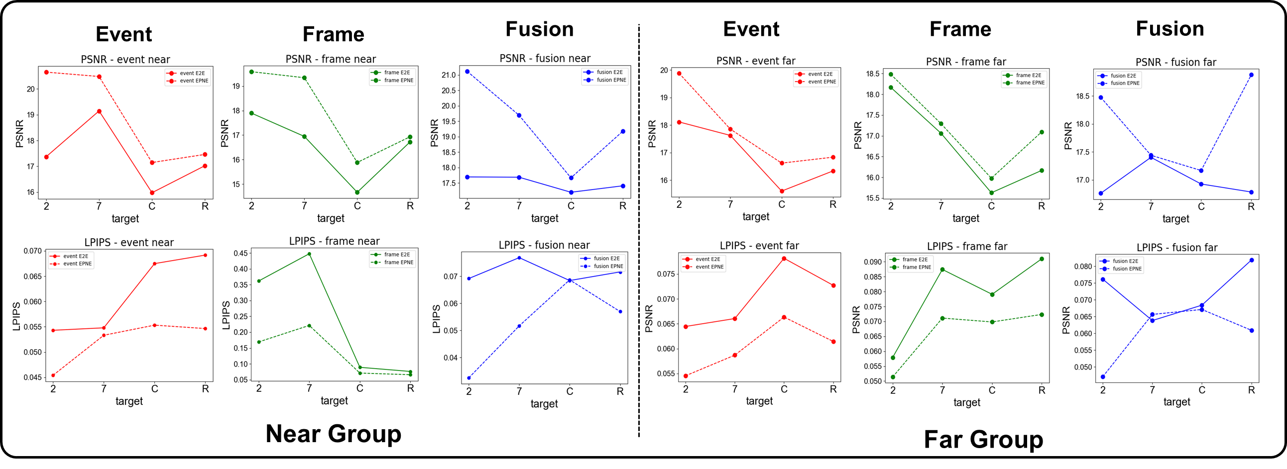
We also use PSNR and LPIPS as the evaluation metrics, and the average scores of each target reconstruction are listed in Table 4. The best and second-best indicators are marked in red and blue respectively. It is obvious that the event-based paradigm and fusion paradigm perform better than the frame-based counterpart, which verifies the superiority of event-based applications in passive NLOS imaging for moving targets.
| Target | Near group | Far group | ||||||||||
|---|---|---|---|---|---|---|---|---|---|---|---|---|
| PSNR/dB | LPIPS | PSNR/dB | LPIPS | |||||||||
| frame | event | fusion | frame | event | fusion | frame | event | fusion | frame | event | fusion | |
| C | 15.88 | 17.14 | 17.66 | 0.071 | 0.055 | 0.070 | 15.97 | 16.62 | 17.16 | 0.069 | 0.066 | 0.067 |
| R | 16.93 | 17.46 | 19.18 | 0.066 | 0.054 | 0.056 | 17.09 | 16.93 | 18.88 | 0.072 | 0.061 | 0.060 |
| 2 | 19.58 | 20.64 | 21.12 | 0.169 | 0.045 | 0.032 | 18.46 | 19.88 | 18.49 | 0.051 | 0.051 | 0.047 |
| 7 | 19.34 | 20.47 | 19.69 | 0.221 | 0.053 | 0.051 | 17.29 | 17.85 | 17.44 | 0.071 | 0.058 | 0.065 |
In addition, comparisons of reconstructions through E2E and PNPE method are shown in Figure 11, with three data formats respectively. The reconstruction of the PNPE method perform better than that of the E2E method in most cases, which demonstrates the importance of embedding physical restrains into the data-driven approach in passive NLOS imaging.
5 Discussions
5.1 Results analysis
From the comparison of objective evaluation indicators between the three data paradigms listed in Table 4, the event and fusion paradigm outperforms the frame paradigm on both of the alphabet and the number targets in each distance group. A better performance on PSNR indicates more accurate restoration of textures, and the superiority of LPIPS expresses more conformity with human eye perception, which validate the enhancement brought by event-based sensing for NLOS moving target reconstruction.
Deeply exploring the relationship between information representation and reconstruction results, we find the unique advantage of each data paradigm. It can be seen from the real-shot experiment results that through the PNPE framework, event-based information performs well in reconstructing the texture details, whereas frame-based information is more effective in reconstructing the morphological basis of NLOS moving targets. As a result, fusion of event-based feature with traditional frame-based intensity information is an effective approach to expand and enhance the applicability in practical scenarios.
The curves of PSNR and LPIPS with three dataset paradigms using E2E and PNPE method are compared in Figure. 11. The proposed PNPE method represented by the dotted line achieves better indices on both metrics than the E2E method represented by full lines. The margin of evaluation scores between alphabet targets and number targets is mainly caused by the difference in data distribution and font size, since the targets of ’Comic nums’ are smaller than that of ’Comic letters’.
In addition, the correctness of reconstructions on Comic nums ‘2’ and ‘7’ through PNPE compared with the over-fitting results through the E2E method demonstrate the generalization ability of PNPE when the real-shot dataset is relatively small. Taking the PNPE prototype, more physical constraints from the simulation datasets are embedded and the reconstruction is enhanced in real-world experiments.
5.2 Contributions
In this study, we constructed a passive NLOS system with illuminated moving targets, where event-based and frame-based data are captured for real-shot dataset fabrication. A plug and play prototype PNPE is proposed, leveraging the enhancement provided by physical embedded simulation based on forward model.
Since the main challenge of passive NLOS imaging for moving targets is optimizing the inverse problem under the strong spatio-temporal aliasing interference on the relay surface, the proposed framework can mitigate blindness with the support from physical basis. In addition, the involvement and fusion of event-based vision provides more powerful dynamic feature extraction and representation capabilities, which enhances the reconstruction performance for moving scenes.
5.3 Limitations and Prospects in application
Event paradigm detection shows superior dynamic feature extraction and in-sensor computing capabilities, however, the absolute intensity information is lost during the data acquisition process.
Although TS representation can use spatio-temporal correlation features to reconstruct targets, offloading the importance of absolute intensity information to some extent, without the support of frame-based information, many morphological features are neglected. This leads to shortcomings when reconstructing solid targets or full scenery, in which only contours and textures are reconstructed. Therefore, the application of event-based vision through the physical embedded passive NLOS prototype PNPE still has limitations in static and blocky object imaging, and we could not rely solely on event paradigm information. To solve this, fusion of these two information dimensions are required to ensure better performance and more flexibility in generalization.
We believe that event-based vision opens the door for device-dominated in-sensor computing [57] and sensing methods in NLOS imaging of moving targets. The proposed PNPE prototype will guide the optimization of solving the inverse problem by simulated physical embedding for enhancement in restorations. In future work, more complicated targets of various data distributions can be added to the simulation part with a more accurate forward model expression to further enhance the performance and generalization. In addition, the structure of the embedding module and feature representation format of different information dimension can be studied to ensure high quality pre-training. The application of event-based vision together with the PNPE prototype will not limited to passive NLOS imaging for moving targets. It can be used in more applications where dynamic feature extraction is required or under complex and harsh ambient light field environments. Besides the event feature embedding, more dimensions of the light field could be simulated and used through the PNPE prototype with more suitable network structures.
6 Conclusions
Traditional frame-based data acquisition paradigm exhibits shortcomings in passive NLOS moving target imaging, and the E2E data-driven reconstruction method limits the generalization and applicability with a limited dataset. The movement of hidden targets further increase the blindness of ill-posed inverse problem in temporal dimension. This paper puts forward a step towards overcoming these limitations. Leveraging the sampling paradigm of dynamic vision sensors, an event-based enhanced passive NLOS imaging method with simulated physical embedding is proposed. The PNPE prototype promises to enable high-quality reconstruction of moving targets occluded by obstacles and ensure certain generalization among data distributions.
Specifically, the principles and procedures of the simulation dataset fabrication and target reconstruction with the PNPE framework are illustrated in detail, and the effectiveness is visualized and quantitatively evaluated for comparison with the E2E data-driven framework. The superiority of the proposed method in terms of performance is validated through simulation and real-world experiments. We also discuss the limitations and possible application prospects for future work, which provides a new gateway for physical embedded NLOS reconstruction with extra enhancement with in-sensor computing and feature extraction of different information paradigms.
When artificial intelligence (AI) meets photonics, the effectiveness of information acquisition using novel photonic sensors, coupled with the rationality of information utilization through AI is essential for enhancing the solving process of ill-posed problems. The proposed plug and play structure PNPE has great potential for facilitating further research on physically enhanced and dynamic scene computational imaging applications beyond passive NLOS imaging.
Funding National Natural Science Foundation of China (62031018).
Acknowledgments The authors thank Dr. Yutong He for insightful discussions.
Disclosures The authors declare no conflicts of interest.
Data Availability. Data underlying the results presented in this paper are not publicly available at this time but will be available on github upon acceptance.
References
- [1] A. Kirmani, T. Hutchison, J. Davis, et al., “Looking around the corner using transient imaging,” in IEEE 12th International Conference on Computer Vision (ICCV) (2009), pp. 159.
- [2] T. Maeda, G. Satat, T. Swedish, et al., “Recent advances in imaging around corners,” arXiv:1910.05613 (2019).
- [3] D. Faccio, A. Velten, and G. Wetzstein, “Non-line-of-sight imaging,” Nat. Rev. Phys. 2, 318 (2020).
- [4] O. Gupta, T. Willwacher, A. Velten, et al., “Reconstruction of hidden 3D shapes using diffuse reflections,” Opt. Express 20, 19096-19108 (2012).
- [5] R. Geng, Y. Hu, Y. Chen, et al., “Recent advances on non-line-of-sight imaging: Conventional physical models, deep learning, and new scenes,” APSIPA Transactions on Signal and Information Processing, 11, 1 (2021).
- [6] M. Buttafava, J. Zeman, A. Tosi, et al., “Non-line-of-sight imaging using a time-gated single photon avalanche diode,” Opt. Express 23, 20997-21011 (2015).
- [7] A. Velten, D. Wu, A. Jaraboet, et al. Femto-photography: capturing and visualizing the propagation of light. ACM Trans. Graph. 32, 1-8 (2013).
- [8] S. Shen, Z. Wang, P. Liu, et al., "Non-line-of-Sight Imaging via Neural Transient Fields," in IEEE Trans. Pattern Anal. Mach. Intell. 43, 2257 (2021).
- [9] X. Feng, L. Gao, “Ultrafast light field tomography for snapshot transient and non-line-of-sight imaging,” Nat. Commun. 12, 2179 (2021).
- [10] B. Wang, M. Zheng, J. Han, et. al, “Non-Line-of-Sight Imaging with Picosecond Temporal Resolution,” Phys. Rev. Lett. 127, 053602 (2021).
- [11] W. Chen, S. Daneau, C. Brosseau, et al., "Steady-State Non-Line-Of-Sight Imaging," 2019 IEEE/CVF Conference on Computer Vision and Pattern Recognition (CVPR) (2019), pp. 6783-6792.
- [12] A. Velten, T. Willwacher, O. Gupta, et al., “Recovering three-dimensional shape around a corner using ultrafast time-of-flight imaging,” Nat. Commun. 3, 745-752 (2012).
- [13] Z. Li, J. Ye, X. Huang, et al., "Single-photon imaging over 200 km," Optica 8, 344-349 (2021).
- [14] X. Liu, I. Guillén, M. La Manna et al., Non-line-of-sight imaging using phasor-field virtual wave optics. Nature 572, 620-623 (2019).
- [15] C. Jin, J. Xie, S. Zhang et al., "Richardson-Lucy deconvolution of time histograms for high-resolution non-line-of-sight imaging based on a back-projection method," Opt. Lett. 43, 5885 (2018).
- [16] M. O’Toole, D. Lindell, G. Wetzstein, "Confocal non-line-of-sight imaging based on the light-cone transform," Nature 555, 338-341 (2018).
- [17] J. Ye, X. Huang, Z. Li, et al., "Compressed sensing for active non-line-of-sight imaging," Opt. Express 29, 1749-1763 (2021).
- [18] D. Lindell, G. Wetzstein, M. O’Toole, "Wave-based non-line-of-sight imaging using fast fk migration," ACM T. Graphic. 38, 1-13 (2019).
- [19] J. Klein, M. Laurenzis, M. B. Hullin, et al., "A calibration scheme for non-line-of-sight imaging setups," Opt. Express 28, 28324-28342 (2020)
- [20] Y. Wang, Z. Wang, B. Zhao, et al., "Propagate and Calibrate: Real-Time Passive Non-Line-of-Sight Tracking," 2023 IEEE/CVF Conference on Computer Vision and Pattern Recognition (CVPR) (2023) pp. 972-981.
- [21] J.H. Nam, E. Brandt, S. Bauer, et al., “Low-latency time-of-flight non-line-of-sight imaging at 5 frames per second,” Nat Commun 12, 6526 (2021).
- [22] C. A. Metzler, F. Heide, P. Rangarajan, et al., "Deep-inverse correlography: towards real-time high-resolution non-line-of-sight imaging," Optica 7, 63-71 (2020).
- [23] A. Beckus, A. Tamasan and G. K. Atia, "Multi-Modal Non-Line-of-Sight Passive Imaging," in IEEE Trans. Image Process. 28, 3372 (2019).
- [24] Y. Wang, Y. Zhang, M. Huang et al., “Accurate but fragile passive non-line-of-sight recognition,” Commun. Phys. 4, 88 (2021).
- [25] J. Mait, G. Euliss, R. Athale, "Computational imaging," Adv. Opt. Photon. 10, 409-483 (2018).
- [26] O. Katz, P. Heidmann, M. Fink, et al., “Non-invasive single-shot imaging through scattering layers and around corners via speckle correlations,” Nat. Photon 8, 784-790 (2014).
- [27] C. Saunders, J. Murray-Bruce, V. Goyal, “Computational periscopy with an ordinary digital camera,” Nature 565, 472–475 (2019).
- [28] K. Tanaka, Y. Mukaigawa, A. Kadambi, Proceedings of the IEEE/CVF Conference on Computer Vision and Pattern Recognition (CVPR) (2020) pp. 2136-2145.
- [29] T. Maeda, Y. Wang, R. Raskar, et al., "Thermal Non-Line-of-Sight Imaging," 2019 IEEE International Conference on Computational Photography (ICCP)(2019) pp. 1-11.
- [30] J. Boger-Lombard, O. Katz, “Passive optical time-of-flight for non line-of-sight localization,” Nat. Commun 10, 3343 (2019).
- [31] C. Hashemi, R. Avelar and J. Leger, "Isolating Signals in Passive Non-Line-of-Sight Imaging using Spectral Content," in IEEE Trans. Pattern Anal. Mach. Intell. (2023).
- [32] G. Gariepy, F. Tonolini, R. Henderson, et al., “Detection and tracking of moving objects hidden from view,” Nat. Photonics 10, 23-26 (2016).
- [33] S. Chan, R. Warburton, G. Gariepy, et al., “Non-line-of-sight tracking of people at long range,” Opt. Express 25, 10109-10117 (2017).
- [34] J. He, S. Wu, R. Wei, et al., "Non-line-of-sight imaging and tracking of moving objects based on deep learning," Opt. Express 30, 16758-16772 (2022).
- [35] G. Gallego, T. Delbruck, G. M. Orchard et al., “Event-based vision: a survey,” IEEE Trans. Pattern Anal. Mach. Intell. 44, 154 (2020).
- [36] F. Mu, S. Mo, J. Peng, et al., "Physics to the Rescue: Deep Non-Line-of-Sight Reconstruction for High-Speed Imaging," in IEEE Trans. Pattern Anal. and Mach. Intell., 1-12 (2022).
- [37] G. Barbastathis, A. Ozcan, and G. Situ, "On the use of deep learning for computational imaging," Optica 6, 921-943 (2019).
- [38] S. Zheng, M. Liao, F. Wang et al., "Non-line-of-sight imaging under white-light illumination: a two-step deep learning approach," Opt. Express 29, 40091-40105 (2021).
- [39] Y. Li, J. Peng, J. Ye et al., Proceedings of the IEEE/CVF Conference on Computer Vision and Pattern Recognition (CVPR) (2023) pp. 13313-13322.
- [40] Y. Cao, R. Liang, W. Zhu, et al., “Dynamic-excitation-based steady-state non-line-of-sight imaging via multi-branch convolutional neural network,” Opt. Laser. Eng., 161, 107369 (2023).
- [41] S. Wu, C. Huang, J. Lin et al., "Physics-constrained deep-inverse point spread function model: toward non-line-of-sight imaging reconstruction," Adv. Photon. Nexus, 3, 026010 (2024).
- [42] W. Chen, F. Wei, K. Kutulakos, et al., “Learned feature embeddings for non-line-of-sight imaging and recognition,” ACM Trans. Graph. 39, 1-18, (2020).
- [43] C. Wang, Y. He, X. Wang, et. al, “Passive non-line-of-sight imaging for moving targets with an event camera,” Chin. Opt. Lett., 21, 061103 (2023).
- [44] H. Rebecq, R. Ranftl, V. Koltun, et al., “High speed and high dynamic range video with an event camera,” IEEE Trans. Pattern Anal. Mach. Intell. 43, 1964 (2021).
- [45] L. Xu, W. Xu, V. Golyanik et al., "EventCap: Monocular 3D capture of high-speed human motions using an event camera", Proc. IEEE/CVF Conf. Comput. Vis. Pattern Recognit. (CVPR)(2020) pp.4967-4977.
- [46] S. Schaefer, D. Gehrig and D. Scaramuzza, "AEGNN: Asynchronous event-based graph neural networks", Proc. IEEE/CVF Conf. Comput. Vis. Pattern Recognit. (CVPR)(2022) pp. 12361-12371.
- [47] R. Geng, Y. Hu, Z. Lu, et al., “Passive non-line-of-sight imaging using optimal transport,” IEEE Trans. Image Process. 31, 110 (2021).
- [48] C. Wang, X. Wang, C. Yan, et al., “Feature representation and compression methods for event-based data,” IEEE Sens. J. 23, 5109 (2023).
- [49] X. Lagorce, G. Orchard, F. Galluppi, et al., “HOTS: a hierarchy of event-based time-surfaces for pattern recognition,” IEEE Trans. Pattern Anal. Mach. Intell. 39, 1346 (2017).
- [50] W. Zhang, H. Zhang, C. Sheppard, et al., "Analysis of numerical diffraction calculation methods: from the perspective of phase space optics and the sampling theorem," J. Opt. Soc. Am. A 37, 1748-1766 (2020).
- [51] A. Gandjbakhche and G. Weiss, “Random walk and diffusion-like models of photon migration in turbid media,” Prog. Opt. 34, 333-402 (1995).
- [52] G. Rogers, “Random walk analysis for reflectance and transmission of turbid media,” Color Res. Appl. 41, 580-584 (2016).
- [53] G. Rogers, "Transmission point spread function of a turbid slab," J. Opt. Soc. Am. A 36, 1617-1623 (2019)
- [54] Y. Hu, S. Liu, T. Delbruck, “v2e: From Video Frames to Realistic DVS Events,” Proceedings of the IEEE/CVF Conference on Computer Vision and Pattern Recognition (CVPR) Workshops (2021) pp. 1312-1321.
- [55] P.J. Grother, K.K. Hanaoka, NIST Special Database 19 Handprinted Forms and Characters Database, https://www.nist.gov/srd/nist-special-database-19.
- [56] R. Zhang, P. Isola, A. A. Efros et al., “The unreasonable effectiveness of deep features as a perceptual metric,” in IEEE/CVF Conference on Computer Vision and Pattern Recognition (CVPR) (2018) pp. 586-595.
- [57] F. Zhou, Y. Chai, “Near-sensor and in-sensor computing,” Nat. Electron 3, 664-671 (2020).