On the Fly Robotic-Assisted Medical Instrument Planning and Execution Using Mixed Reality
Abstract
Robotic-assisted medical systems (RAMS) have gained significant attention for their advantages in alleviating surgeons’ fatigue and improving patients’ outcomes. These systems comprise a range of human-computer interactions, including medical scene monitoring, anatomical target planning, and robot manipulation. However, despite its versatility and effectiveness, RAMS demands expertise in robotics, leading to a high learning cost for the operator. In this work, we introduce a novel framework using mixed reality technologies to ease the use of RAMS. The proposed framework achieves real-time planning and execution of medical instruments by providing 3D anatomical image overlay, human-robot collision detection, and robot programming interface. These features, integrated with an easy-to-use calibration method for head-mounted display, improve the effectiveness of human-robot interactions. To assess the feasibility of the framework, two medical applications are presented in this work: 1) coil placement during transcranial magnetic stimulation and 2) drill and injector device positioning during femoroplasty. Results from these use cases demonstrate its potential to extend to a wider range of medical scenarios.
I INTRODUCTION
Robotic-assisted medical systems (RAMS) have been rapidly developing and revolutionizing the paradigm in operating rooms in recent years. These systems are capable of enhancing dexterity, alleviating fatigue for medical staff, and minimizing errors during surgical procedures [1]. These benefits are attributed to dedicated consoles that allow dexterous surgical operations and versatile imaging modalities that ensure the representation of intricate anatomy.
One of the core functionalities of RAMS is to position and manipulate medical instruments such as drills, milling tools, or endoscopes through a console [2, 3, 4]. However, the operation of RAMS usually leads to a visual discontinuity in which the operator needs to shift focus from instruments to the screen of the navigation system, thereby detracting attention from patients [5, 6]. The absence of a line of sight to the anatomical site can increase the likelihood of medical errors such as unintended collision and sub-optimal tool placement. A constant need to switch focus would intensify the operator’s fatigue and reduce efficiency during the procedure. Thus, it is beneficial to develop an informative and uninterrupted human-robot interface for RAMS. To this end, emerging mixed reality (MR) technologies shed light on potential solutions to the challenges [7].
The integration of MR and robotic systems in medical applications has enhanced the operator’s ability in perceiving anatomical structures and surgical plans that are overlaid on real-world scenes [8, 9, 10, 11]. Motivated by mitigating the gap between inexperienced operators and the required robot programming skills, researchers proposed novel MR frameworks to enable intuitive and easy-to-learn robot programming and teaching interfaces [12, 13, 14, 15, 16]. Moreover, methodologies to convey motion intents of robots to humans have been investigated to ensure safe human-robot collaboration [17, 18, 19]. These works commonly focus on enhancing the operator’s perception and control over the robotic system, yet they overlook the importance of informing the robot about the operator’s status. The integration of anatomy visualization with robot programming interfaces, coupled with human-robot mutual perception (i.e., both the operator and the robot are aware of each other), has not been fully explored in RAMS.
In this paper, we propose a novel RAMS framework based on MR and human-robot mutual perception for medical instrument planning and execution. The framework enables the visualization of anatomical overlay and uses a hand-held device to facilitate the localization of anatomical targets. A converter is designed to transform the operator’s avatar into detectable objects, allowing the robot to be aware of the operator’s location and prevent possible collisions. In addition, a robot programming interface is developed for trajectory preview and waypoint adjustment.
Before implementing the proposed system, one of the indispensable prerequisites is to overlay rendered virtual objects with their physical counterparts. The accuracy of the overlay can affect user experience and the effectiveness of planning. Researchers have proposed various methods to calibrate the transformation from the virtual scene to the real world. These methods include registering two movement sets acquired by a head-mounted display (HMD) and an external tracking system [20], manually aligning virtual landmarks with their real counterparts [21], and registering the point clouds of virtual model and real scene [13]. Existing methods require repetitive virtual-to-real calibration after each launch of the MR application, making the procedure time-consuming. As the amount of rendered graphics increases, running online calibration algorithms becomes even more challenging due to the limited computation resources of HMDs. To simplify the calibration process and enhance its reusability, we propose a virtual-to-real calibration method by combining an external tracking system and an inside-out tracking module of MR-HMDs developed by [22].
To evaluate the feasibility of the proposed framework, we implemented the system in two medical use cases: coil placement in Transcranial Magnetic Stimulation (TMS) and drill and injector positioning in femoroplasty (detailed in section III).
In this work, we made the following contributions:
-
1.
A novel RAMS framework that combines MR and human-robot mutual perception to provide safe medical instrument planning and execution.
-
2.
An easy-to-use method for virtual-to-real calibration that facilitates the overlay of virtual scenes onto the real world.
-
3.
Evaluation of the proposed framework, including the virtual-to-real calibration method and the instrument alignment results using two medical use cases.
II Method
II-A System Description
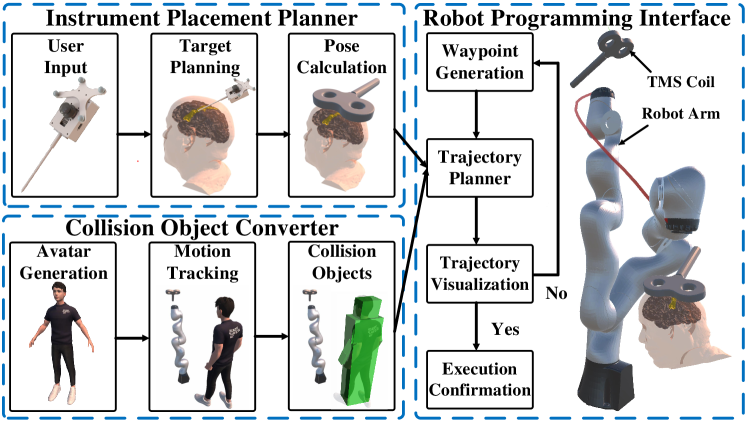
The system comprises three main modules: an interface for instrument placement planning, a collision object converter based on avatar, and a robot programming interface. Together, these components help the operator observe the patient’s anatomy in-situ, preview the planned trajectory of the robot, and enable secure execution of tool placement.
II-A1 Instrument Placement Planner
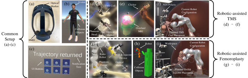
The instrument placement planner, shown in Fig.1, allows the operator to determine the anatomical target of interest and intuitively preview the placement. Before confirming the target, the operator is able to observe the overlay of the patient’s magnetic resonance imaging (MRI), which is preprocessed by medical image segmentation tools [23] and 3D computer graphics software [24, 25]. By viewing the MRI overlay, the operator can focus on the region of interest and plan the target with a customized hand-held device (clicker). The clicker, equipped with a microcontroller, an optical marker, a probe, and a joystick, can assist the operator with determining anatomical targets in-situ without shifting focus to conventional displays. A virtual ray of light is projected along the probe’s axis, which intersects with the segmented medical image. On the projected area, a colored spot designates the target position in real time. After pressing the joystick, the operator can define an initial target position and subsequently fine-tune it using the joystick. The target position is then sent to the instrument pose calculator described in [26] and [27]. The preview of the instrument uses the calculated pose, and assists the operator in understanding the intended placement pose.
II-A2 Collision Object Converter
Since previewing the planned pose of the instrument can help the operator identify potential sub-optimal placements that cause inconvenience or injury to the patient. Likewise, enabling the robot’s awareness of the operator may help to eliminate potential collision when the robot is in motion. To achieve this, an avatar representing the operator is created using Ready Player Me 111Ready Player Me, Inc., Estonia. An HMD (Microsoft HoloLens 2) is then used to capture the motion of the operator and map that motion to the avatar. Considering the HMD’s limitation in capturing full-body motion, hand-tracking and head-tracking results of the HMD are transformed, using inverse kinematics, to reconstruct the configuration of the avatar’s upper limbs and head, respectively. The avatar’s main components, including upper limbs, head, and main body, are then converted to simple geometric shapes and are considered as collision objects in the robot trajectory planner (see Collision Object Converter in Fig.1). By converting the operator’s avatar to collision objects, the framework can help the robot obtain the spatial information of the operator and avoid potential collisions.
II-A3 Robot Programming Interface
Once the instrument’s placement pose is confirmed, the operator can send it to the robot trajectory planner, which is supported by the motion planning framework MoveIt! [28]. Taking the collision objects into consideration, the planner will plan a collision-free trajectory and send it back to the HMD. This step allows the operator to preview the robot’s trajectory overlaid on the real world. If the current trajectory lacks in safety or precision, the operator has the option to modify the trajectory’s waypoints and re-plan it to achieve better outcomes. Once satisfied with the planned trajectory, the operator can then confirm the execution of instrument placement (see Fig.1, Robot Programming Interface).
II-B System Kinematics
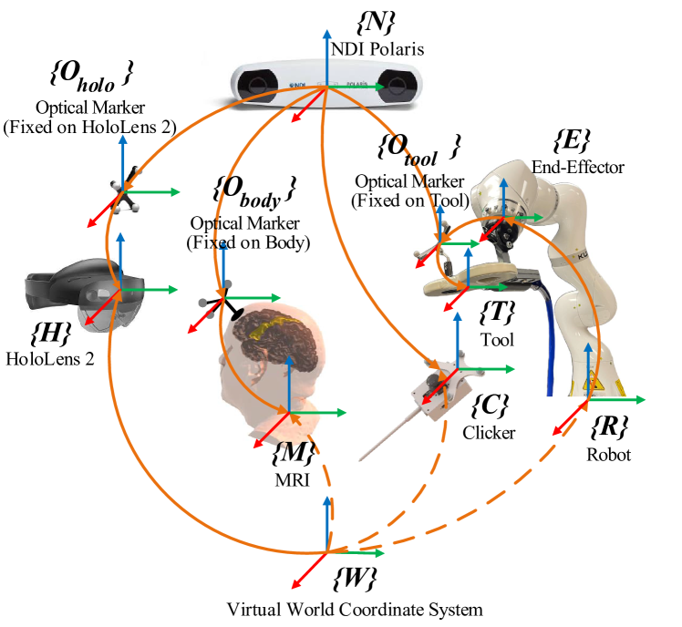
Determining the placement of the medical instrument on the targeted anatomy or understanding the operator’s relative position to the robot requires the kinematic transformations between each object. An external tracking system (NDI Polaris Vicra 222Polaris NDI, Northern Digital Incorporated. Ontario, Canada) is used to track the optical markers attached to the objects. The kinematic chain of the system in robotic-assisted TMS is shown in Fig. 2. As the figure denotes, the proposed system incorporates multiple components, including an HMD (HoloLens 2), the patient’s body with its MRI, a clicker, a TMS coil, and a robot.
The transformation from the optical marker fixed on the HMD to the HMD’s local coordinate system, depicted in Fig 2, is obtained through the virtual-to-real calibration described in Section II-D. The system requires subject-image registration to align the MRI with the subject’s body, as well as instrument calibration to find the poses of the instrument relative to the robot and the tracking system. We register the medical image to the subject by paired-point registration and Iterative Closest Point (ICP) algorithms [29, 30, 31, 26]. Additionally, instrument calibration is done by using the tool center calibration method presented in [27] and the geometry-based end-effector calibration method described in [32].
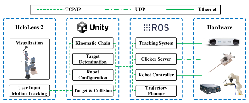
II-C System Communication
To improve the performance of the HMD (i.e., HoloLens 2), we run the application on Unity 3D using the Holographic Remoting functionality supported by Microsoft. The communication of the proposed system (Fig. 3) connects the HMD to a PC through TCP/IP and allows the PC to perform graphics rendering, significantly reducing the computation load of the HMD. Correspondingly, the HoloLens 2 streams back user input and motion tracking results to the applications on PC. The applications then map the motion to the avatar and converts the avatar to collision objects. Along with the target pose of the instrument, the collision objects are sent to the trajectory planner of MoveIt!. The Robot Operating System (ROS) and the integrated medical robotic system in [26] are responsible for connecting the hardware, including the tracking system, the clicker, and the robot.
II-D Virtual-to-Real Calibration
II-D1 Calibration Method
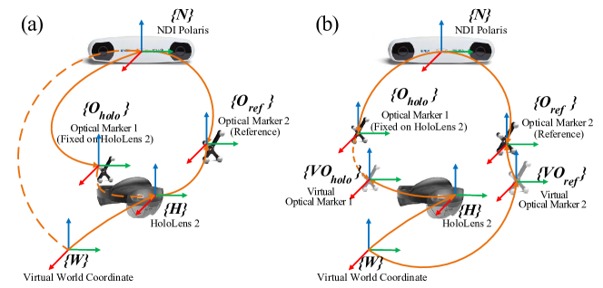
Accurate virtual-to-real calibration ensures the proper overlay of the rendered graphics onto physical objects. Before computing the transformation from the virtual world coordinate system to the external tracking system (shown in Fig. 4), the proposed method first determines the transformation between the HMD’s local coordinate system and the optical maker on the HMD . Besides the external tracking system (i.e., NDI Polaris), an inside-out tracking module (STTAR) deployed on HoloLens 2 is used [22, 33]. STTAR utilizes the built-in cameras of HoloLens 2 to localize passive retro-reflective markers and has sub-millimeter accuracy when used within 250 mm to 750 mm in depth. Considering the larger range and better accuracy provided by NDI Polaris [34, 22], the proposed system only uses STTAR in the virtual-to-real calibration as an auxiliary tool for measurement.
The calibration scheme is shown in Fig. 4a. We use both tracking systems to track a reference optical marker that is not attached to HoloLens 2 and then calculate the transformation :
| (1) |
where the transformation from HoloLens 2 to the reference optical marker is obtained by STTAR, and the transformation matrices and are obtained by NDI Polaris. Integrating into the known kinematic chain, we can derive the transformation from the virtual world coordinate system to the NDI Polaris coordinate system:
| (2) |
With the transformation between the virtual scene and the real world, we can overlay virtual content onto real-world objects correctly. The calibration does not rely on the operator’s skills. In addition, [35] has shown that the pose of the optical marker with respect to the device’s origin is unchanged. Thus, the calibration result is reusable.
II-D2 Calibration Evaluation
Though the virtual-to-real calibration can be achieved without human bias, the evaluation still depends on the operator’s perception. The kinematic chains of the evaluation method are shown in Fig. 4b. In this method, we manually place the physical reference marker in a known position and align a virtual reference marker on it. We can get the transformation between two real markers ( and ) through NDI Polaris and the transformation between two virtual markers ( and ) through HoloLens 2. Then, we can calculate the virtual-to-real calibration error which is the transformation from the real optical marker to the virtual optical marker :
| (3) |
III Medical Use Cases
In this section, we show the implementation details of the proposed framework in two medical cases: coil alignment in robot-assisted TMS, and drilling and injection device alignment in robot-assisted femoroplasty.
III-A Robotic-Assisted TMS
TMS is a non-invasive neuro-modulation technique that uses rapidly changing magnetic fields to stimulate a specific region of the brain. It is used in the study of brain function [36, 37, 38] and the treatment of psychiatric and neurological disorders [38, 39]. TMS procedure typically involves placing a TMS coil that generates focused magnetic pulses over the head to induce micro-currents in a cortical area. Robotic-assisted TMS has shown promising advantages in improving repeatability and accuracy for TMS coil placement and avoiding operator’s fatigue by eliminating the need for manual alignment [40, 41, 27, 26]. Nevertheless, novel interaction and visualization methods in the context of robotic-assisted TMS have not been explored. In this work, we assess the feasibility and the instrument placement accuracy of the proposed MR framework deployed on robotic-assisted TMS.
TMS coil placement is an alignment task that moves the robot-held coil to a planned pose by commanding the robot. The planned pose of the TMS coil represents the desired pose on the scalp corresponding to a target cortical location in the brain. Accordingly, the MR framework for robot-assisted TMS has the following workflow:
-
1.
The operator registers the MRI to the subject’s head and calibrates the TMS coil with the robot.
- 2.
-
3.
The preview of the coil placement is presented to the operator who can either start the robot trajectory planning or redefine the target location by using the clicker.
-
4.
Incorporating the spatial information of the operator, the trajectory planner of MoveIt! takes the potential collision into consideration and generates a feasible trajectory.
-
5.
By observing the trajectory overlaid onto the real world, the operator has the option to redefine waypoints to create new trajectories or proceed with the placement if it aligns with expectations.
III-B Robotic-Assisted Femoroplasty
Femoroplasty, or femoral bone augmentation, is a minimally invasive surgical procedure designed to prevent hip fractures [42, 43]. In femoroplasty, bone cement is injected into the proximal femur to increase its strength [44, 45]. Previous works have explored surgical trajectory planning and execution in femoroplasty and developed robotic methods to improve drilling and injection accuracy [46, 47, 48].
The main task of robot-assisted femoroplasty is to align a custom-designed Robotic Drilling and Injection Device (RDID) to the line connecting the greater trochanter surface of the femur and the injection point [48]. The use case of robot-assisted femoroplasty shares the same kinematics shown in Fig. 2. The workflow of the femoroplasty adheres to the same policy of the TMS case and also involves subject-image registration, anatomical target planning, instrument pose computation, robot trajectory planning, and placement execution.
IV Experiments
IV-A Experiment Setup
The proposed system operates on two host PCs. PC 1 is equipped with an Intel Core i7-12700H Processor, 16 GB DDR5 RAM, and an NVIDIA GeForce RTX 3060 Laptop GPU. It runs Unity 2021.3.8f1 with the Mixed Reality Toolkit (MRTK) 2.8.2 on Windows 10 and connects with a Microsoft HoloLens 2 via the Holographic Remoting Player 2.9.1. Meanwhile, PC 2 runs ROS Ubuntu 20.04 and interfaces with a robotic arm (LBR iiwa 7 R800 robot, Kuka, Germany) and an optical tracking system (NDI Polaris Vicra, Northern Digital Inc., Canada). A microcontroller (Nano 33 IoT, Arduino, Italy) embedded in the clicker communicates with the ROS network via UDP. The experiment setup can be viewed in Fig. 5.
IV-B Experiment Results
IV-B1 Evaluation of Virtual-to-Real Calibration
For error analysis, we conducted 50 trials of virtual-to-real calibrations in which the operator held the HMD and placed the reference optical marker in different poses each time. After obtaining the calibration results, the operator performed the evaluation by aligning a virtual reference marker, using hand gestures and a keyboard, to the real marker in a single trial. Fig. 6 shows both translation and rotation errors of the calibration error defined in section II-D2. The overall translation error (Euclidean) is mm, and the rotation error (angle-axis representation) is °.

IV-B2 Evaluation of Medical Cases
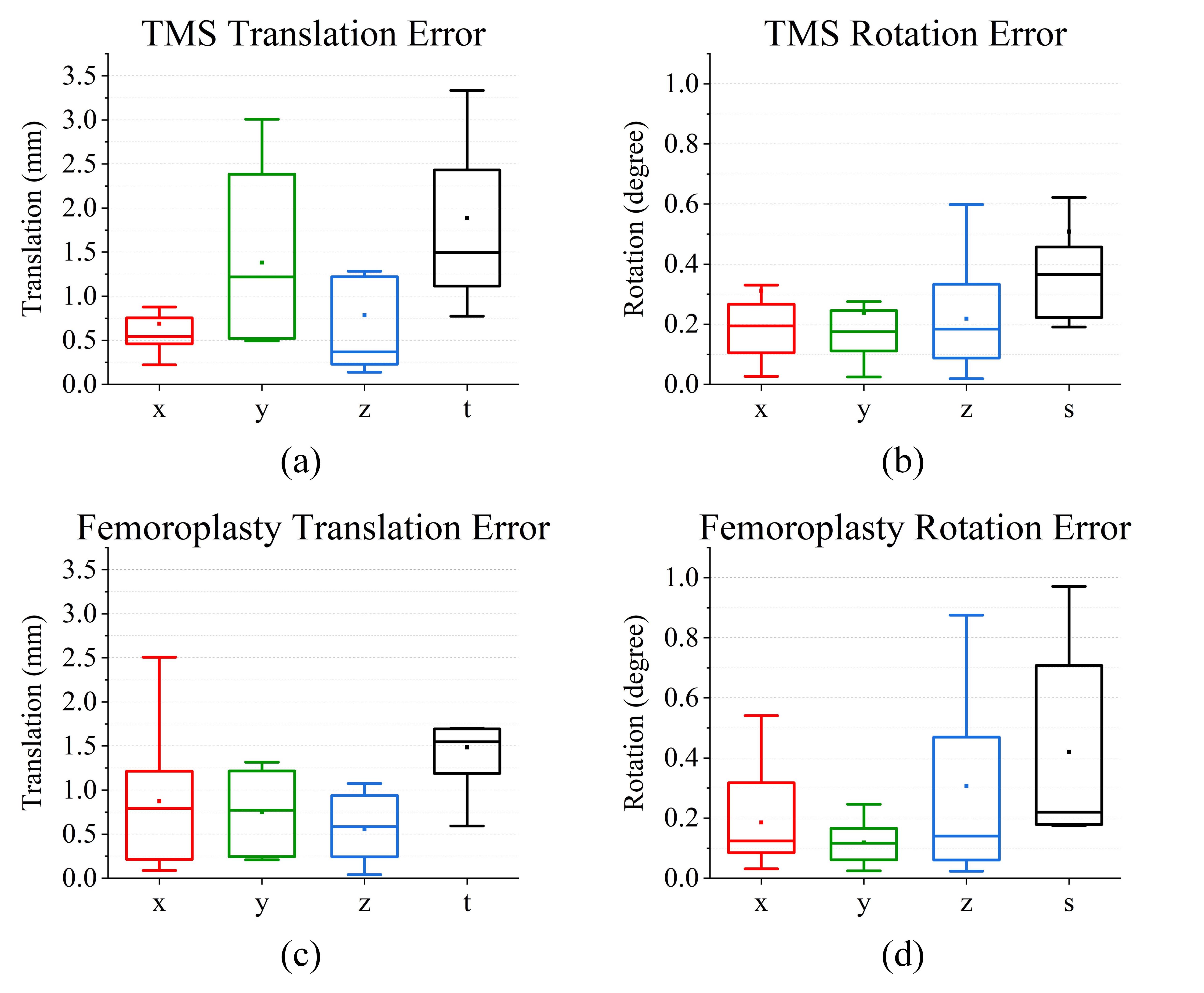
We conducted 10 trials of different alignments for each medical case. In each trial, we use the proposed framework to plan a target pose on the body (phantom head for TMS and phantom femur for femoroplasty) and command the robot to execute the alignment. Fig. 7 shows the alignment errors between the planned and executed target poses. The average translation errors of TMS and femoroplasty are below 2 mm ( mm and mm, respectively), while the average rotation errors are below ( and , respectively). The results show the viability and accuracy of the system in both medical cases.
V Discussion
Compared with the sub-millimeter accuracy of STTAR and NDI Polaris, the calibration errors in translation were relatively large. The issue may arise from the insufficient alignment skills and perception bias of the operator since a small rotation difference in the alignment could cause a large translational offset. An user study that involves multi-users and multi-trials may better reflect the quality of the calibration. The calibration process requires the operator to hold the HMD and collect the data. Thus, the other error sources may include the tremor of the operator and the data asynchrony between the HMD and the tracking system. The translation accuracy might be further improved with an auxiliary stand for stabilizing the HMD.
The calibration error affects the accuracy in determining the anatomical target. However, it does not affect the kinematic accuracy of the robot execution which depends on subject-image registration and instrument calibration instead. The decoupled relationship is supported by the low translation and rotation errors in the medical cases compared to the calibration error. The calibration result also affects collision avoidance which needs the pose of the operator. To compensate for the calibration error, the operator could set a larger volume for each geometric shape converted from the avatar.
Since the current work only presents a technical pilot study, a detailed user study is required to thoroughly validate the robustness and efficacy of the proposed framework. This study should involve recruiting participants to contrast our method with the traditional RAMS. A more comprehensive data analysis could be carried out after obtaining sufficient user samples. Additionally, further improvements are worth exploring such as developing multimodal input and feedback for the hand-held device and enhancing the robustness of the trajectory planning process that considers the dynamic nature of human motions.
VI Conclusion
In this work, we propose a novel RAMS framework using MR to facilitate the planning and execution of medical instrument placement. The framework provides informative image overlays and a handheld device for the identification of anatomical targets. Additionally, the proposed system ensures safe human-robot interaction through mutual perception. An easy-to-implement calibration technique is also presented to align virtual content and the real world accurately. The system was verified through its application in two medical scenarios: robot-assisted TMS and femoroplasty. The results demonstrate the system’s practical viability and its potential for broader application in various RAMS contexts.
References
- [1] J. Klodmann, C. Schlenk, A. Hellings-Kuß, T. Bahls, R. Unterhinninghofen, A. Albu-Schäffer, and G. Hirzinger, “An introduction to robotically assisted surgical systems: Current developments and focus areas of research,” Current Robotics Reports, vol. 2, no. 3, pp. 321–332, 2021.
- [2] H. H. Hassanalideh and S. Gholampour, “Finding the optimal drill bit material and proper drilling condition for utilization in the programming of robot-assisted drilling of bone,” CIRP Journal of Manufacturing Science and Technology, vol. 31, pp. 34–47, 2020.
- [3] N. Sugano, “Computer-assisted orthopaedic surgery and robotic surgery in total hip arthroplasty,” Clinics in orthopedic surgery, vol. 5, no. 1, pp. 1–9, 2013.
- [4] M. Zhou, Q. Yu, K. Huang, S. Mahov, A. Eslami, M. Maier, C. P. Lohmann, N. Navab, D. Zapp, A. Knoll, et al., “Towards robotic-assisted subretinal injection: A hybrid parallel–serial robot system design and preliminary evaluation,” IEEE Transactions on Industrial Electronics, vol. 67, no. 8, pp. 6617–6628, 2019.
- [5] Z. Qi, Y. Li, X. Xu, J. Zhang, F. Li, Z. Gan, R. Xiong, Q. Wang, S. Zhang, and X. Chen, “Holographic mixed-reality neuronavigation with a head-mounted device: technical feasibility and clinical application,” Neurosurgical Focus, vol. 51, no. 2, p. E22, 2021.
- [6] S. Skyrman, M. Lai, E. Edström, G. Burström, P. Förander, R. Homan, F. Kor, R. Holthuizen, B. H. Hendriks, O. Persson, et al., “Augmented reality navigation for cranial biopsy and external ventricular drain insertion,” Neurosurgical Focus, vol. 51, no. 2, p. E7, 2021.
- [7] L. Qian, J. Y. Wu, S. P. DiMaio, N. Navab, and P. Kazanzides, “A review of augmented reality in robotic-assisted surgery,” IEEE Transactions on Medical Robotics and Bionics, vol. 2, no. 1, pp. 1–16, 2019.
- [8] R. Wen, L. Yang, C.-K. Chui, K.-B. Lim, and S. Chang, “Intraoperative visual guidance and control interface for augmented reality robotic surgery,” in IEEE ICCA 2010. IEEE, 2010, pp. 947–952.
- [9] R. Wen, C.-B. Chng, C.-K. Chui, K.-B. Lim, S.-H. Ong, and S. K.-Y. Chang, “Robot-assisted rf ablation with interactive planning and mixed reality guidance,” in 2012 IEEE/SICE International Symposium on System Integration (SII), 2012, pp. 31–36.
- [10] R. Wen, W.-L. Tay, B. P. Nguyen, C.-B. Chng, and C.-K. Chui, “Hand gesture guided robot-assisted surgery based on a direct augmented reality interface,” Computer Methods and Programs in Biomedicine, vol. 116, no. 2, pp. 68–80, 2014, new methods of human-robot interaction in medical practice.
- [11] R. Wen, B. P. Nguyen, C.-B. Chng, and C.-K. Chui, “In situ spatial ar surgical planning using projector-kinect system,” in Proceedings of the 4th Symposium on Information and Communication Technology, ser. SoICT ’13. New York, NY, USA: Association for Computing Machinery, 2013, p. 164–171.
- [12] S. Y. Gadre, E. Rosen, G. Chien, E. Phillips, S. Tellex, and G. Konidaris, “End-user robot programming using mixed reality,” in 2019 International conference on robotics and automation (ICRA). IEEE, 2019, pp. 2707–2713.
- [13] M. Ostanin, S. Mikhel, A. Evlampiev, V. Skvortsova, and A. Klimchik, “Human-robot interaction for robotic manipulator programming in mixed reality,” in 2020 IEEE International Conference on Robotics and Automation (ICRA). IEEE, 2020, pp. 2805–2811.
- [14] M. Q. Tram, J. M. Cloud, and W. J. Beksi, “Intuitive robot integration via virtual reality workspaces,” in 2023 IEEE International Conference on Robotics and Automation (ICRA), 2023, pp. 11 654–11 660.
- [15] J. Krieglstein, G. Held, B. A. Bálint, F. Nägele, and W. Kraus, “Skill-based robot programming in mixed reality with ad-hoc validation using a force-enabled digital twin,” in 2023 IEEE International Conference on Robotics and Automation (ICRA). IEEE, 2023, pp. 11 612–11 618.
- [16] J. Fu, M. C. Palumbo, E. Iovene, Q. Liu, I. Burzo, A. Redaelli, G. Ferrigno, and E. De Momi, “Augmented reality-assisted robot learning framework for minimally invasive surgery task,” in 2023 IEEE International Conference on Robotics and Automation (ICRA). IEEE, 2023, pp. 11 647–11 653.
- [17] E. Rosen, D. Whitney, E. Phillips, G. Chien, J. Tompkin, G. Konidaris, and S. Tellex, “Communicating robot arm motion intent through mixed reality head-mounted displays,” in Robotics Research: The 18th International Symposium ISRR. Springer, 2020, pp. 301–316.
- [18] U. Gruenefeld, L. Prädel, J. Illing, T. Stratmann, S. Drolshagen, and M. Pfingsthorn, “Mind the arm: realtime visualization of robot motion intent in head-mounted augmented reality,” in Proceedings of Mensch und Computer 2020, 2020, pp. 259–266.
- [19] G. Bolano, Y. Fu, A. Roennau, and R. Dillmann, “Deploying multi-modal communication using augmented reality in a shared workspace,” in 2021 18th International Conference on Ubiquitous Robots (UR). IEEE, 2021, pp. 302–307.
- [20] J. Elsdon and Y. Demiris, “Augmented reality for feedback in a shared control spraying task,” in 2018 IEEE International Conference on Robotics and Automation (ICRA). IEEE, 2018, pp. 1939–1946.
- [21] E. Azimi, L. Qian, N. Navab, and P. Kazanzides, “Alignment of the virtual scene to the tracking space of a mixed reality head-mounted display,” arXiv preprint arXiv:1703.05834, 2017.
- [22] A. Martin-Gomez, H. Li, T. Song, S. Yang, G. Wang, H. Ding, N. Navab, Z. Zhao, and M. Armand, “Sttar: surgical tool tracking using off-the-shelf augmented reality head-mounted displays,” IEEE Transactions on Visualization and Computer Graphics, 2023.
- [23] A. Fedorov, R. Beichel, J. Kalpathy-Cramer, J. Finet, J.-C. Fillion-Robin, S. Pujol, C. Bauer, D. Jennings, F. Fennessy, M. Sonka, et al., “3d slicer as an image computing platform for the quantitative imaging network,” Magnetic resonance imaging, vol. 30, no. 9, pp. 1323–1341, 2012.
- [24] Blender Online Community, Blender - a 3D modelling and rendering package, Blender Foundation, Blender Institute, Amsterdam,
- [25] P. Cignoni, M. Callieri, M. Corsini, M. Dellepiane, F. Ganovelli, and G. Ranzuglia, “MeshLab: an Open-Source Mesh Processing Tool,” in Eurographics Italian Chapter Conference, V. Scarano, R. D. Chiara, and U. Erra, Eds. The Eurographics Association, 2008.
- [26] Y. Liu, A. Kheradmand, and M. Armand, “Toward process controlled medical robotic system,” arXiv preprint arXiv:2308.05809, 2023.
- [27] Y. Liu, S. J. Liu, S. Sefati, T. Jing, A. Kheradmand, and M. Armand, “Inside-out tracking and projection mapping for robot-assisted transcranial magnetic stimulation,” in Optical architectures for displays and sensing in augmented, virtual, and mixed reality (AR, VR, MR) III, vol. 11931. SPIE, 2022, pp. 57–70.
- [28] D. Coleman, I. Sucan, S. Chitta, and N. Correll, “Reducing the barrier to entry of complex robotic software: a moveit! case study,” arXiv preprint arXiv:1404.3785, 2014.
- [29] K. S. Arun, T. S. Huang, and S. D. Blostein, “Least-squares fitting of two 3-D point sets,” IEEE Transactions on Pattern Analysis and Machine Intelligence, vol. 9, no. 5, pp. 698–700, 1987.
- [30] P. J. Besl and N. D. McKay, “Method for registration of 3-d shapes,” in Sensor fusion IV: control paradigms and data structures, vol. 1611. Spie, 1992, pp. 586–606.
- [31] C. Maurer, J. Fitzpatrick, M. Wang, R. Galloway, R. Maciunas, and G. Allen, “Registration of head volume images using implantable fiducial markers,” IEEE Trans. on Medical Imaging, vol. 16, no. 4, pp. 447–462, Aug 1997.
- [32] Y. Liu, J. Zhang, Z. She, A. Kheradmand, and M. Armand, “Gbec: Geometry-based hand-eye calibration,” In press, accepted for publication in: The 2024 IEEE International Conference on Robotics and Automation (ICRA2024).
- [33] A. Keller, “Hololens 2 infrared retro-reflector tracking,” https://github.com/andreaskeller96/HoloLens2-IRTracking, 2023.
- [34] G. Fattori, A. J. Lomax, D. C. Weber, and S. Safai, “Technical assessment of the ndi polaris vega optical tracking system,” Radiation oncology, vol. 16, no. 1, pp. 1–4, 2021.
- [35] D. Ungureanu, F. Bogo, S. Galliani, P. Sama, X. Duan, C. Meekhof, J. Stühmer, T. J. Cashman, B. Tekin, J. L. Schönberger, et al., “Hololens 2 research mode as a tool for computer vision research,” arXiv preprint arXiv:2008.11239, 2020.
- [36] A. T. Barker, R. Jalinous, and I. L. Freeston, “Non-invasive magnetic stimulation of human motor cortex,” The Lancet, vol. 325, no. 8437, pp. 1106–1107, 1985.
- [37] D. E. Bohning, A. Shastri, Z. Nahas, J. P. Lorberbaum, S. W. Andersen, W. R. Dannels, E.-U. Haxthausen, D. J. Vincent, and M. S. George, “Echoplanar bold fmri of brain activation induced by concurrent transcranial magnetic stimulation,” Investigative radiology, vol. 33, no. 6, pp. 336–340, 1998.
- [38] A. Chail, R. K. Saini, P. Bhat, K. Srivastava, and V. Chauhan, “Transcranial magnetic stimulation: a review of its evolution and current applications,” Industrial psychiatry journal, vol. 27, no. 2, p. 172, 2018.
- [39] V. Di Lazzaro, R. Bella, A. Benussi, M. Bologna, B. Borroni, F. Capone, K.-H. S. Chen, R. Chen, A. V. Chistyakov, J. Classen, M. C. Kiernan, G. Koch, G. Lanza, J.-P. Lefaucheur, H. Matsumoto, J.-P. Nguyen, M. Orth, A. Pascual-Leone, I. Rektorova, P. Simko, J.-P. Taylor, S. Tremblay, Y. Ugawa, R. Dubbioso, and F. Ranieri, “Diagnostic contribution and therapeutic perspectives of transcranial magnetic stimulation in dementia,” Clinical Neurophysiology, vol. 132, no. 10, pp. 2568–2607, 2021.
- [40] S. Harquel, J. Diard, E. Raffin, B. Passera, G. Dall’Igna, C. Marendaz, O. David, and A. Chauvin, “Automatized set-up procedure for transcranial magnetic stimulation protocols,” Neuroimage, vol. 153, pp. 307–318, 2017.
- [41] A. Noccaro, A. Mioli, M. D’Alonzo, M. Pinardi, G. Di Pino, and D. Formica, “Development and validation of a novel calibration methodology and control approach for robot-aided transcranial magnetic stimulation (tms),” IEEE Transactions on Biomedical Engineering, vol. 68, no. 5, pp. 1589–1600, 2021.
- [42] J. Beckmann, S. J. Ferguson, M. Gebauer, C. Luering, B. Gasser, and P. Heini, “Femoroplasty–augmentation of the proximal femur with a composite bone cement–feasibility, biomechanical properties and osteosynthesis potential,” Medical engineering & physics, vol. 29, no. 7, pp. 755–764, 2007.
- [43] E. G. Sutter, S. C. Mears, and S. M. Belkoff, “A biomechanical evaluation of femoroplasty under simulated fall conditions,” Journal of orthopaedic trauma, vol. 24, no. 2, p. 95, 2010.
- [44] J. Beckmann, R. Springorum, E. Vettorazzi, S. Bachmeier, C. Lüring, M. Tingart, K. Püschel, O. Stark, J. Grifka, T. Gehrke, et al., “Fracture prevention by femoroplasty—cement augmentation of the proximal femur,” Journal of Orthopaedic Research, vol. 29, no. 11, pp. 1753–1758, 2011.
- [45] A. Farvardin, E. Basafa, M. Bakhtiarinejad, and M. Armand, “Significance of preoperative planning for prophylactic augmentation of osteoporotic hip: A computational modeling study,” Journal of biomechanics, vol. 94, pp. 75–81, 2019.
- [46] E. Basafa, R. J. Murphy, Y. Otake, M. D. Kutzer, S. M. Belkoff, S. C. Mears, and M. Armand, “Subject-specific planning of femoroplasty: an experimental verification study,” Journal of biomechanics, vol. 48, no. 1, pp. 59–64, 2015.
- [47] A. Farvardin, M. Bakhtiarinejad, R. J. Murphy, E. Basafa, H. Khanuja, J. K. Oni, and M. Armand, “A biomechanically-guided planning and execution paradigm for osteoporotic hip augmentation: Experimental evaluation of the biomechanics and temperature-rise,” Clinical Biomechanics, vol. 87, p. 105392, 2021.
- [48] M. Bakhtiarinejad, C. Gao, A. Farvardin, G. Zhu, Y. Wang, J. K. Oni, R. H. Taylor, and M. Armand, “A surgical robotic system for osteoporotic hip augmentation: System development and experimental evaluation,” IEEE Transactions on Medical Robotics and Bionics, vol. 5, no. 1, pp. 18–29, 2023.