Online Learning of Joint-Muscle Mapping Using Vision in Tendon-driven Musculoskeletal Humanoids
Abstract
The body structures of tendon-driven musculoskeletal humanoids are complex, and accurate modeling is difficult, because they are made by imitating the body structures of human beings. For this reason, we have not been able to move them accurately like ordinary humanoids driven by actuators in each axis, and large internal muscle tension and slack of tendon wires have emerged by the model error between its geometric model and the actual robot. Therefore, we construct a joint-muscle mapping (JMM) using a neural network (NN), which expresses a nonlinear relationship between joint angles and muscle lengths, and aim to move tendon-driven musculoskeletal humanoids accurately by updating the JMM online from data of the actual robot. In this study, the JMM is updated online by using the vision of the robot so that it moves to the correct position (Vision Updater). Also, we execute another update to modify muscle antagonisms correctly (Antagonism Updater). By using these two updaters, the error between the target and actual joint angles decrease to about 40% in 5 minutes, and we show through a manipulation experiment that the tendon-driven musculoskeletal humanoid Kengoro becomes able to move as intended. This novel system can adapt to the state change and growth of robots, because it updates the JMM online successively.
I INTRODUCTION
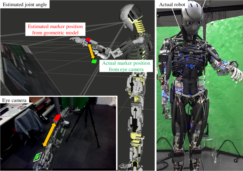
Tendon-driven musculoskeletal humanoids [1, 2, 3, 4] are expected to play an active part in human society in the future, because they have multiple degrees of freedom (multi-DOFs) like the scapula and spine of human beings, can realize variable stiffness, are soft in contact, etc. However, the accurate modeling of tendon-driven musculoskeletal humanoids is difficult, because they are made by imitating human beings and so they have complex muscle arrangements and body structures. It is difficult to move them accurately like ordinary humanoids driven by actuators in each axis, if we use only their geometric models (Fig. 1). Also, internal muscle tension and slack of tendon wires tend to emerge because of the model error between its geometric model and the actual robot. Thus, in order for tendon-driven musculoskeletal humanoids to gain popularity, we need a novel system by which an exact geometric model is not necessary, and instead the movement information of the actual robot is used in order to move the robots accurately as intended.
In previous studies, various controls were developed in order to move tendon-driven musculoskeletal humanoids as intended, and decrease the internal muscle tension and slack of tendon wires. Ookubo, et al. [5] and Jäntsch, et al. [6] obtained data of joint angles and muscle lengths from the actual robot by moving the humanoid, acquired a joint-muscle mapping (JMM) which expresses a nonlinear relationship between joint angles and muscle lengths by polynomial regression of the data, and moved it accurately by using this JMM. Also, Kawaharazuka, et al. [7] estimated the muscle antagonism and decreased the internal muscle tension and slack of tendon wires by inhibiting antagonist muscles against agonist muscles. However, these methods do not update JMM online, and cannot adapt to the state change of the actual robots according to the elongation of tendon wires. Also, in the studies of [5] and [6], we must obtain numerous data from the actual robot, and it is difficult to apply these methods to JMMs including multi-DOFs like human beings due to its computational complexity. In other studies, several controls consider muscle synergy [8]. Among them, Diamond et al. [9] implemented an algorithm using muscle synergy and reinforcement learning for a reaching task. This method realizes a simple algorithm using muscle synergy, and the reaching movement can be improved in each trial, but the experiment is done only in a simulation environment, and there are some problems regarding the number of trials, lack of versatility, etc.
To solve these problems, we propose a novel system which conducts online learning of JMM using the vision of tendon-driven musculoskeletal humanoids. In this system, JMM is expressed using neural network (NN), and muscle jacobian is obtained by differentiating the JMM. The humanoid itself looks at part of its body such as its hands and feet, and becomes able to move accurately by modifying the JMM online using data of the actual robot. At the same time, we do another online update of the JMM to correct internal muscle tension and slack of tendon wires. This study does not consider the influence of muscle compliance, and deals with only the condition in which no forces, except for gravity, are applied to the robot. Also, we assume that the geometric model regarding the joint structure of the robot is correct.
Using this proposed system, manipulation tasks, which were challenging for tendon-driven musculoskeletal humanoids to execute using only its geometric model, can be done by updating JMM accurately online using the data of the actual robot. Thus, this system can be adapted to the growth and state change of robots.
This paper is organized as follows. In Section I, we stated the motivation and the goal of this study. In Section II, as an introduction to this system, we will explain the method of training JMM, obtaining muscle jacobian, updating JMM online, and estimating joint angles. In Section III, we will explain the overview of this system and two types of online learnings of JMM. In Section IV, we will conduct some basic experiments about respective components of this system, and discuss the effectiveness of this study through a manipulation task experiment. Finally, in Section V, we will state the conclusion and the future works.
II Learning of Joint-Muscle Mapping using a Neural Network
To express JMM, methods using table-searching [10], polynomial regression [6, 5], and NN [11] have been proposed. The methods using table-searching and polynomial regression have a problem that the computational cost increases exponentially in accordance with the increase of included joints, and are not good at online updating of JMM. The positive side to using polynomial regression is that we can obtain smooth muscle jacobian by differentiating. In comparison, the expression using NN is good at online updating, but we cannot obtain smooth muscle jacobian by differentiating. Jäntsch, et al. [11] collected the data set to train NN only at first, and there is no discussion about the methods to obtain smooth muscle jacobian, to estimate joint angles, and to update JMM online.
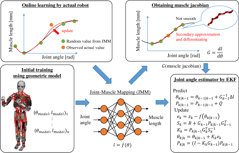
Thus, in this study, we express JMM using NN in order to make online learning of JMM possible. At first, though the difference between the geometric model and the actual robot is large, we construct JMM using the information of the geometric model. After that, we modify the JMM obtained from the geometric model using the information from the movement of the actual robot. In this section, we will explain the method of training JMM from a geometric model, obtaining smoothened muscle jacobian, updating JMM online, and estimating joint angles. The overview of the expression of JMM using NN is shown in Fig. 2, and we will explain the respective components below.
II-A Initial Training of Joint-Muscle Mapping from a Geometric Model
In this study, a function which expresses a nonlinear relationship between joint angles and muscle lengths:
| (1) |
is expressed by neural network, which has 3 layers: an input layer of joint angles, a hidden layer, and an output layer of muscle lengths. is muscle lengths and is joint angles.
First, we construct a simple geometric model of a tendon-driven musculoskeletal humanoid. In this study, we use Kengoro [4] (the details are in Section IV-A). This geometric model is a simple one composed of muscles in which the starting point, relay points, and end point are connected (the lower left figure of Fig. 2). Next, we construct JMM for each respective body part such as the shoulder, scapula, neck, and so on. For the example of the shoulder, when we construct the JMM including 3 DOFs glenohumeral joint and 1 DOF elbow joint, we pick up muscles which move these 4 DOFs (in this study, 10). If these muscles include polyarticular muscles which move other DOFs beside these 4 DOFs, we must add those other DOFs to the JMM of the shoulder. Thus, the JMM of 4 DOFs around the shoulder is the nonlinear relationship between 10 muscles which move these 4 DOFs and all joints which these 10 muscles can move (for example, the pectoralis major muscle can move scapula joints in addition to the shoulder joints). In this case, there are 8 DOFs including the 4 DOFs scapula (we limit the DOF of the scapula to 4 DOFs: roll and yaw of sternoclavicular joint, and roll and pitch of acromioclavicular joint). Through this process, the JMM of the shoulder is composed of 8 DOFs and 10 muscles. We construct the other JMMs likewise. Although it is possible to construct a JMM including all DOFs and muscles of the entire body, this is difficult due to its computational complexity, and this is one of our future works.
Finally, we train these JMMs by the geometric model of the tendon-driven musculoskeletal humanoid. We move respective joint angles of the geometric model little by little, calculate the muscle lengths, and construct a data set. Using this data set, we train NN of JMM.
The JMM obtained from the geometric model has almost the same value as the geometric model. However, as shown in Fig. 1, there is a large error between this JMM and the actual robot, so we need to modify it using the information from the movement of the actual robot.
II-B Derivation of Muscle Jacobian from Neural Network
We obtained JMM by training NN using the data set of the geometric model. An important component in controlling tendon-driven musculoskeletal humanoids is the muscle jacobian:
| (2) |
and we must differentiate NN to obtain this muscle jacobian. However, though the JMM expressed using NN is differentiable, because the JMM is the superposition of activation functions, differentiation results in the appearance of each function’s features. For example, when we use sigmoid as an activation function, the differentiated value can be wavy due to the feature of sigmoid, and when we use ReLu, the value can be jagged in the same way. To solve this problem, we obtain muscle jacobian by secondary approximation using some sample points. When joint angles of the robot is , to obtain the muscle jacobian of a certain muscle and joint , we get some sample points of muscle length when moving joint by degrees (in this study, we sampled 5 points: and 4 points which have [deg] interval each from in the positive and negative direction), solve secondary approximation from the data set, and obtain smoothened muscle jacobian by differentiating it.
| (3) | |||
| (4) | |||
| (5) | |||
| (6) |
where are coefficients of secondary approximation, and is the muscle length of .
In addition, there are several other methods to smoothen muscle jacobian, such as the weight decay and minimization of network structure.
II-C Online Learning of Joint-Muscle Mapping from Movement Data of the Actual Robot
In order to become able to move the actual robot accurately, we need to update the weights of NN obtained from the geometric model. However, if we simply update NN, a difference in update frequency emerges among joint angles, and this can cause over-fitting. To decrease the difference of update frequency among joint angles, in addition to the data which we want to update, we use the data of the initial value (meaning when all joint angles are 0, muscle lengths are also 0) and the sets of data which are collected randomly from the current JMM (in this study, 8 sets of data), and update NN by dataset as minibatch.
| (7) |
The concept is shown in the upper left figure of Fig. 2. We succeeded in updating NN online gradually without destroying the entire value of JMM.
II-D The Estimation of Joint Angles
Tendon-driven musculoskeletal humanoids do not have sensors measuring joint angles such as encoders and potentiometers because they have many ball joints imitating joints of human beings. So, we need to estimate current joint angles from expansion and contraction of muscles. In this study, to estimate joint angles, we use the method of Ookubo, et al. [5]. This method uses extended kalman filter (EKF), and we substitute the NN output of this study for the muscle jacobian and the function calculating muscle lengths from joint angles in this method. Specifically, for muscle jacobian and the function in the state equation and observation equation of EKF as shown below, we use the value obtained by NN output.
| (8) | ||||
| (9) |
III Online Learning System
III-A Overview
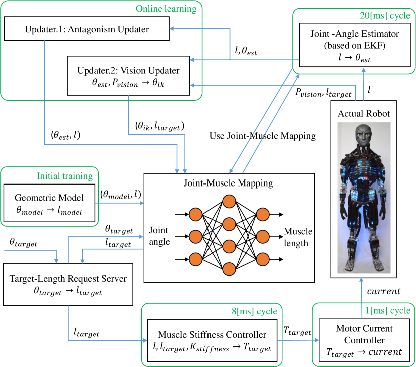
The overview of this system is shown in Fig. 3. We express JMM using NN, and we move the actual robot and estimate joint angles using this JMM. Also, we update this JMM online using two types of methods. The first method is online learning using estimated joint angles and the actual muscle lengths (Antagonism Updater). By this method, we can modify the slack of tendon wires and internal muscle tension between agonist and antagonist muscles that occur due to the model error between the geometric model and actual robot. The second method is online learning using the actual joint angles estimated by vision and target muscle lengths sent to move the actual robot (Vision Updater). By this method, we can decrease the model error between the geometric model and actual robot, and become able to move the actual robot accurately as intended.
III-B Antagonism Updater
This online learning method is very simple; we update JMM using the method explained at Section II-C in which the data set is the current estimated joint angles and actual muscle lengths as shown below.
| (10) |
We update JMM when the change of muscle lengths is smaller than a certain value and when is further from previous by more than a certain value. We will explain the reason why this online learning is able to modify muscle antagonism correctly. First, we move the tendon-driven musculoskeletal humanoid using the procedure below.
-
1.
We set the target joint angles.
-
2.
We calculate target muscle lengths by inputting the target joint angles into JMM.
-
3.
We calculate target muscle tensions using muscle stiffness control [12], and send these to the actual robot.
The equation of muscle stiffness control is shown as below.
| (11) |
This control permits muscle length errors to a certain degree, meaning that it can inhibit internal muscle tension and slack of tendons to a certain degree. This effect of inhibition becomes large when we make smaller and bigger. If there are slack of tendons, makes the slack decrease, and by using the Antagonism Updater in this situation, the antagonism relationship is modified correctly in the direction that decreases the slack of tendons. Also, if there is large internal muscle tension, becomes longer than due to muscle stiffness control, and the internal muscle tension decreases. By using the Antagonism Updater in this situation, we can modify the antagonism relationships correctly in the direction that decreases the large internal muscle tension. Thus, if the sent target muscle lengths are impossible to be executed and large internal muscle tension and slack of tendons emerge, this problem can be solved by updating NN using estimated joint angles and actual muscle lengths which in actuality have no slack of tendon wires and smaller internal muscle tension than the original due to muscle stiffness control.
III-C Vision Updater
In this section, we will explain the method to modify JMM using the RGB camera of Kengoro and AR marker attached to the hand of Kengoro. This method can be applied to not only the hand but also any other part of the body, and we can use the feature value of the body or the value of IMU instead of the AR marker. The procedure of this online learning is stated as below.
-
1.
By looking at the AR marker attached to the hand from the RGB camera in the head, we can obtain the relative position and orientation from the camera to the hand.
-
2.
We obtain the actual joint angles by solving inverse kinematics (IK), in which the initial joint angles are the current estimated joint angles, the target position and orientation are as stated above, and the links are the head, thorax, collarbone, scapula, humerus, ulna and radius.
(12) -
3.
Having omitted any mistakes of the IK (omitted if the actual joint angles are too different from the current estimated joint angles ), we execute online learning using the sent target muscle lengths and actual joint angles.
(13) where expresses L2 norm and is a threshold.
Like the Antagonism Updater, we update JMM when the change of muscle lengths is smaller than a certain value and when is further from previous by more than a certain value.
This method is different from the Antagonism Updater in that this updater can modify the JMM to become able to move the actual robot accurately as intended. We can use the actual muscle lengths instead of the target muscle lengths , in which case we are also able to modify JMM accurately to a certain degree. However, due to muscle stiffness control, there is a difference between the sent muscle lengths and actual muscle lengths. So when using , it is difficult to meet requirements needed to move the actual robot to the intended position, and using is better regarding tracking accuracy.
IV Experiments
We conducted some experiments using the proposed system. First, we will discuss the construction of JMM using NN, and next, we will verify the two types of online learnings, respectively. After that, we will integrate the two online learnings, and execute quantitative analysis on the realization of intended joint angles. Finally, through a manipulation experiment, we will verify the effectiveness of this proposed system.
IV-A Basic Experiments of Joint-Muscle Mapping
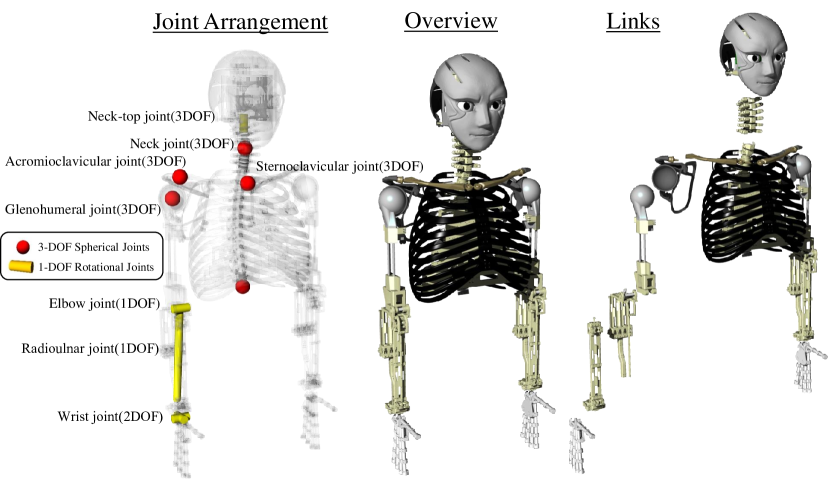
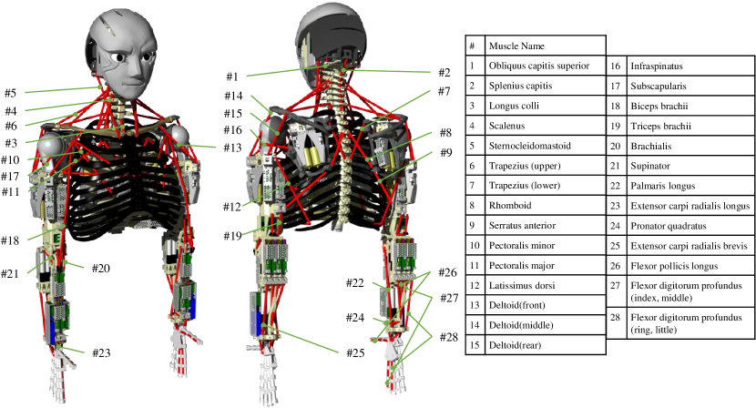
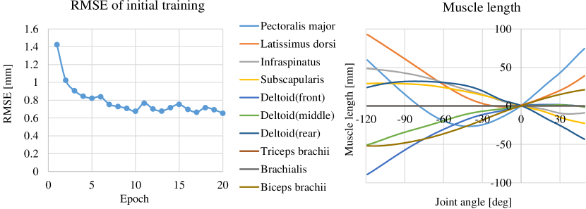
First, we will consider the initial training of JMM from a geometric model. The joint structure of Kengoro’s upper limb (Fig. 4) is the same as in human beings, and we divided it into 4 groups: the neck, scapula, shoulder, and forearm. As stated in Section II-A, we constructed 4 JMMs using NN regarding these respective groups. In this study, the number of hidden layer units is 1000, and the activation function of NN is sigmoid. In the preliminary experiment considering the structure of NN, in the case of 8 DOFs and 10 muscles included in the shoulder JMM, which is the biggest in this study, we verified that one hidden layer and 1000 units in the hidden layer are enough to express the JMM (loss of training is under 1 [mm] as shown in Fig. 6). The unit of input joint angles is [rad], and the unit of output muscle lengths is [mm]. As an example, we show the muscle arrangement of Kengoro upper limb in Fig. 5 and the JMM of the shoulder of Kengoro in Fig. 6. The data set of joint angles and muscle lengths is obtained by equally dividing the range of each joint movement into 5–9 parts and moving the joint angles of the geometric model by each value, and the number of total data was 2646000. In this initial training, the size of minibatch is 5, the number of epoch is 20, the optimization method is Adam, and we used one-fifth of the data set randomly as validation. The loss transition, or the root mean squared error (RMSE), when training is shown in the left graph of Fig. 6. As an example, we show the change of 10 muscle lengths from NN when moving the shoulder pitch axis in the right graph of Fig. 6. From these graphs, we can see that the weight of NN is trained well to a value similar to that of the geometric model.
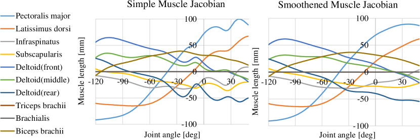
Second, regarding muscle jacobian, we show the muscle jacobian in the pitch direction during shoulder flexion in Fig. 7. In other words, it is a differentiation of the right graph of Fig. 6. When we differentiated simply using analytical differentiation of NN, the graph fluctuated as shown in the left graph of Fig. 7. In comparison, when we differentiated using the method of Section II-B, a smooth and natural graph was obtained as shown in Fig. 7.
IV-B Experiment of Antagonism Updater using Elbow Joint
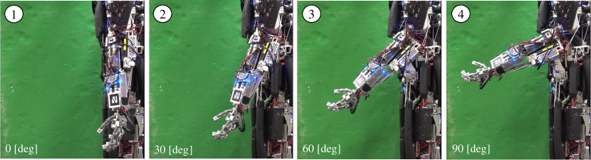
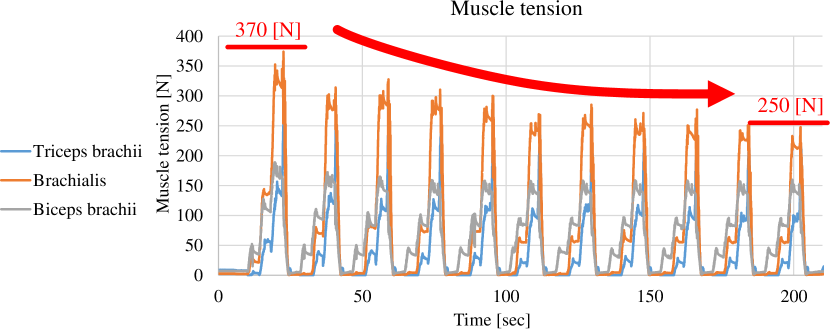
We will show the effectiveness of Antagonism Updater stated in Section III-B through an experiment using the elbow joint. In the elbow joint, there are mainly 3 muscles: the brachialis, biceps brachii, and triceps brachii. In this experiment, we moved the elbow joint of Kengoro up to 90 [deg] by 30 [deg] in 2 second intervals (Fig. 8) continuously. We show the muscle tensions during this experiment in Fig. 9. The graph shows that the two agonist muscle tensions became equal and the antagonist muscle tension decreased gradually during the movement of the elbow joint. In this experiment, maximum muscle tension decreased from 370 [N] to 250 [N] in 11 trials. Although there was a large difference in muscle tensions among agonist muscles (the brachialis and biceps brachii) at first, the difference decreased gradually during the trials. By this experiment, we could verify the effectiveness of the Antagonism Updater. However, as shown in Fig. 8, the joint angles are largely different from the intended angles. This updater only modifies the muscle antagonism. In order to move the actual robot as intended, we conducted an experiment of Vision Updater next.
IV-C Experiment of Vision Updater
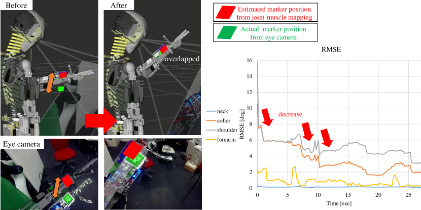
In order to verify the effectiveness of Vision Updater, we will show the correct modification of estimated joint angles during an experiment moving the upper limb of Kengoro and looking at the limb. In this experiment, we sent various joint angles to Kengoro’s upper limb, Kengoro looked at the AR marker attached to the hand from eyes in the head, and updated JMM online using the information. The correct modification of JMM by this updater is shown in Fig. 10. The left figure shows how the estimated position of the AR marker from the current JMM and the position of the AR marker from Kengoro’s RGB camera became close using this updater. Although there was a difference among the two AR marker positions at first, the positions became closer and finally overlapped. The right graph shows the transition of RMSE of the difference between the estimated joint angles from JMM and the actual joint angles estimated using vision, and the RMSE became smaller gradually. For example, the RMSE of the shoulder was about 16 [deg] at first, but it finally decreased to about 3 [deg]. By this experiment, we verified the effectiveness of Vision Updater.
IV-D Experiment of Antagonism Updater and Vision Updater
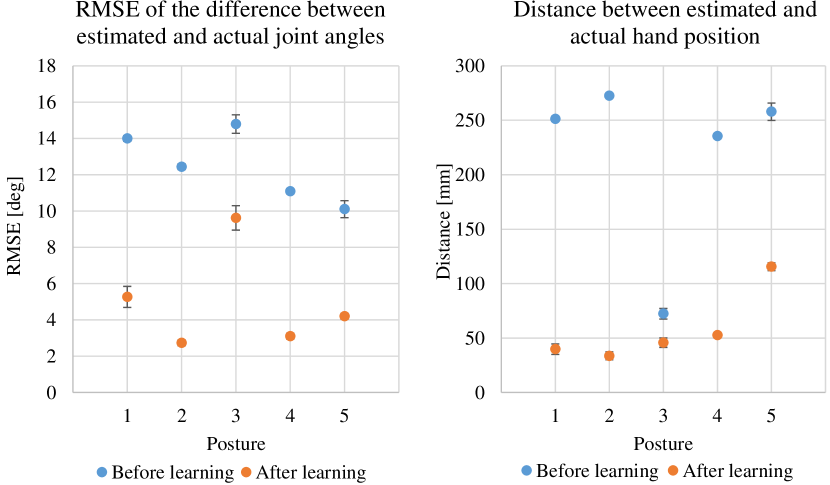
We will integrate the two updaters: Antagonism Updater and Vision Updater, apply them to the actual robot, and show quantitative analysis regarding realization of intended joint angles. We evaluated the average and standard deviation of RMSE of the difference between the estimated and actual joint angles (RMSE of (), ) by repeating the movement from randomized start postures to target postures. As a reference, is almost equal to the we sent, because is estimated using muscle lengths . First, we sent several postures to the robot successively, conducted online learning using the actual robot, and obtained modified JMM. The number of postures we sent during online learning was 27 in 300 [sec]. Next, we generated 5 target postures (named posture 1–5; we checked these postures are feasible and absolute error of joint angles between these postures and all postures we sent during the online learning are distant by at least 20 [deg]), and repeated the movement from 10 randomized start postures to postures 1–5, respectively. We moved the robot from randomized start postures in order to consider the influence of hysteresis and reproducibility. We conducted these trials before and after the online learning (total: 100 trials), and showed in Fig. 11. There are some differences among target postures 1–5, but the average of decreased from before to after the online learning regarding all postures. The standard deviation is very small. Also, we showed the distance between the estimated and actual hand xyz position in Fig. 11. We can see decreases regarding all target postures 1–5. In total, the average of among all trials decreased from 12.49 [deg] to 4.99 [deg]: about 40%, and that of decreased from 217.95 [mm] to 57.53 [mm]: about 26%, regarding before and after the online learning. Thus, the two types of online learning do not compete, have generalization ability, and work effectively.
IV-E Experiment of Can Grasping
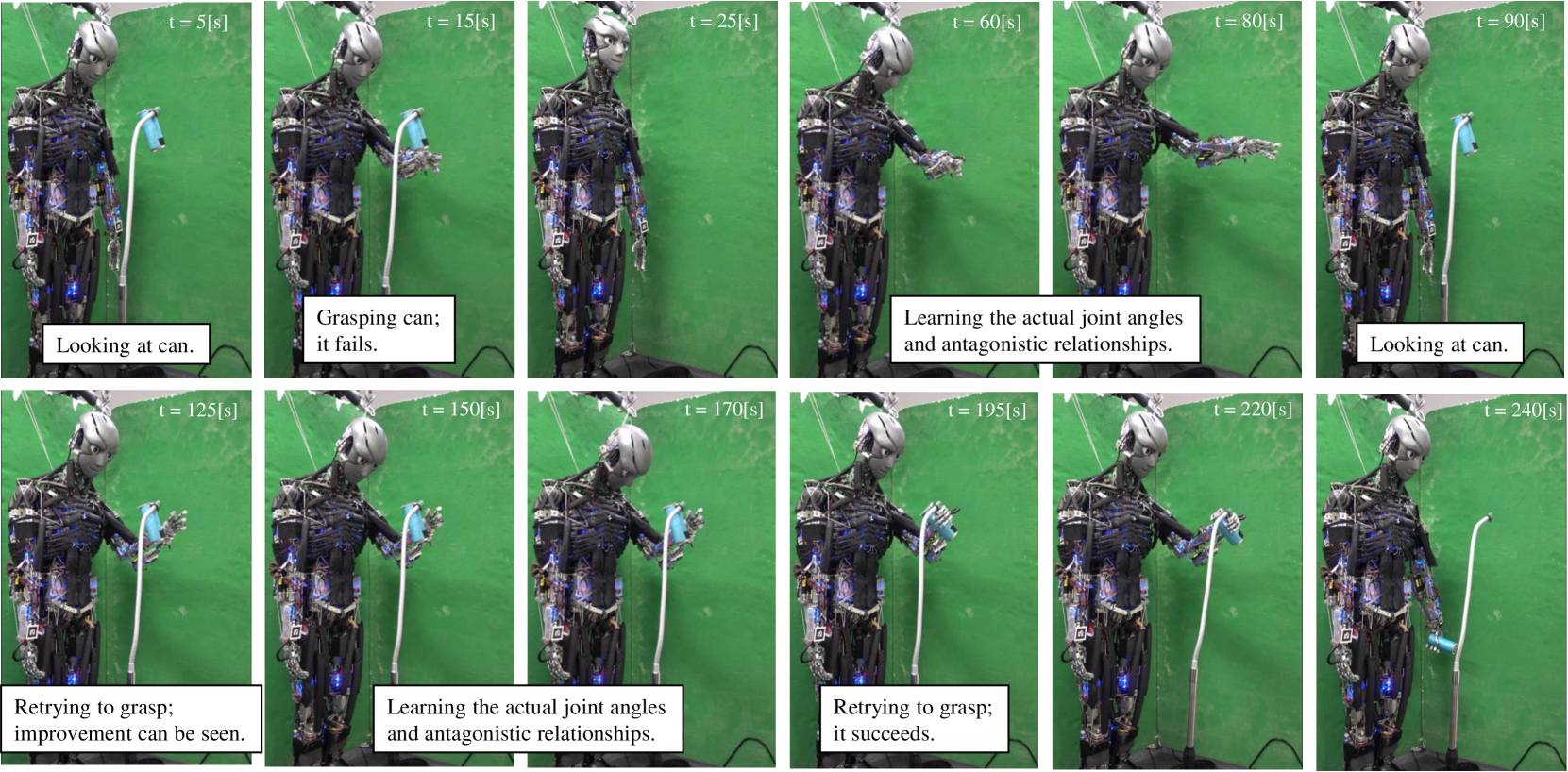
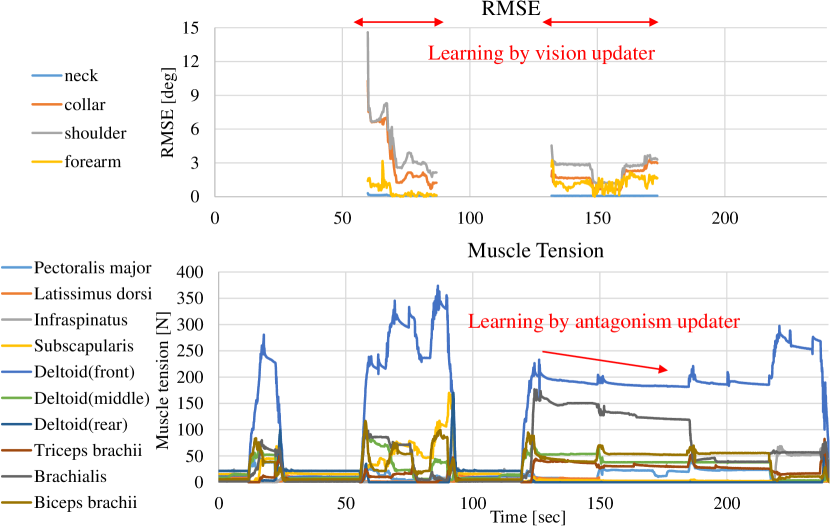
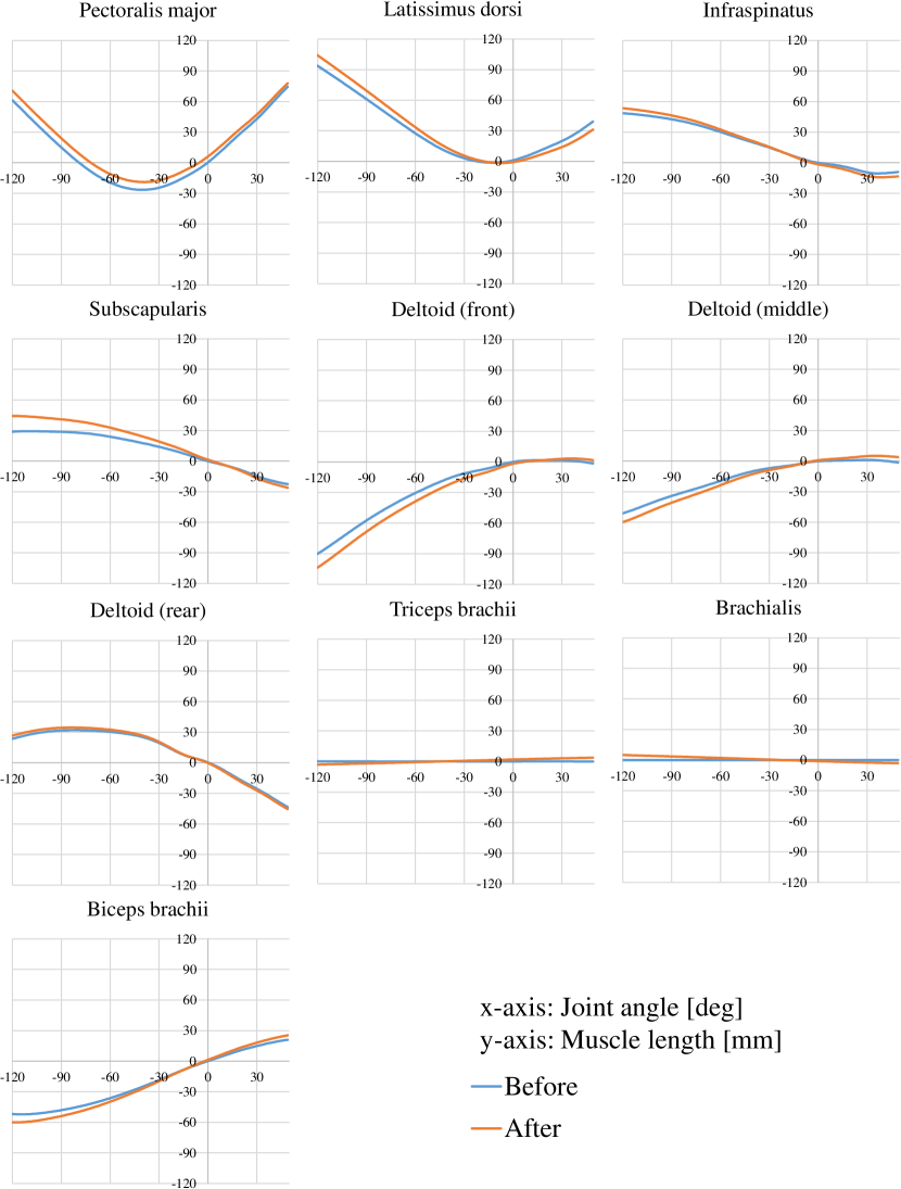
We conducted a manipulation experiment of looking at a can and grasping it, by integrating the entire system proposed in this study. In all experimental movements, the proposed two updaters are executed. How this experiment was carried out is shown in Fig. 12. Also, RMSE of the difference between the estimated joint angles and the actual joint angles using the RGB camera and muscle tensions during this experiment are shown in Fig. 13. We will explain the detailed movements of this experiment. First, Kengoro looked at a can with an AR marker, solved IK at the position of the AR marker, and moved the hand to the position in order to grasp it. However, at first, there were some errors between the geometric model and actual robot, and Kengoro could not move the hand to the intended position. Second, Kengoro moved the upper limb to various positions, and looked at the hand. During these movements, JMMs that are accurate to a certain degree were obtained using Vision Updater. Then, Kengoro approached the can again. The approach to the can became better, but Kengoro could not approach it completely, so he looked at the upper limb again and updated JMM online. Finally Kengoro was able to approach the can correctly and grasp it. In this experiment, the positions at which IK is solved are completely the same, but each actual position of the moved hand is different every time, because the JMM is modified correctly during the movement. Also, as shown in Fig. 13, the RMSE and the required muscle tensions decreased gradually. Finally, in order to visualize the difference of the JMM before and after its update, as an example, we show the transition of 10 muscle lengths in the shoulder during shoulder flexion before and after the update in Fig. 14. Although the overall shape is not destroyed, we can see a difference of 15 [mm] at -120 [deg] between before the update and after.
By this experiment, we verified that this study is effective.
V CONCLUSION
In this study, we showed the method of online learning of joint-muscle mapping (JMM) which modifies the JMM accurately using vision and the actual robot information, in tendon-driven musculoskeletal humanoids which have large model error between the geometric model and actual robot. Although JMM is usually expressed by polynomial regression, table-searching, and so on, we expressed JMM by neural network (NN), allowing for the online update of JMM. We discussed the method of initial training from a geometric model, online learning that prevents over-fitting, and obtaining smooth and natural muscle jacobian. Also, we developed two online updaters of JMM. First, online learning using the current estimated joint angles and actual muscle lengths can modify muscle antagonism correctly, preventing large internal muscle tension and slack of tendon wires (Antagonism Updater). Second, online learning using the actual joint angles estimated from vision and sent target muscle lengths can modify the JMM so that the robot can move to the intended position (Vision Updater). By these online learning methods of JMM, the error between the target and actual joint angles decrease to 40% in 5 minutes, and a manipulation task by tendon-driven musculoskeletal humanoids which have not been done until now due to the model error between the geometric model and actual robot becomes possible. This study is one step for tendon-driven musculoskeletal humanoids to approach and exceed ordinary humanoids driven by actuators in each axis.
In future works, we would like to try two tasks. First, although in this study, we used AR markers attached to the hand in order to obtain the hand position and orientation, the robot should recognize the movement of the hand itself and obtain the information about position and orientation. Second, we want to add the effect of muscle tension to JMM, and manipulate objects more accurately while changing muscle stiffness. In this study, we were unable to consider muscle elongation due to muscle compliance, so next, we should implement online learning of a new model which updates not only joint-muscle mapping, but also the influence of muscle compliance.
References
- [1] Y. Nakanishi, S. Ohta, T. Shirai, Y. Asano, T. Kozuki, Y. Kakehashi, H. Mizoguchi, T. Kurotobi, Y. Motegi, K. Sasabuchi, J. Urata, K. Okada, I. Mizuuchi, and M. Inaba, “Design approach of biologically-inspired musculoskeletal humanoids,” International Journal of Advanced Robotic Systems, vol. 10, no. 4, p. 216, 2013.
- [2] S. Wittmeier, C. Alessandro, N. Bascarevic, K. Dalamagkidis, D. Devereux, A. Diamond, M. Jäntsch, K. Jovanovic, R. Knight, H. G. Marques, P. Milosavljevic, B. Mitra, B. Svetozarevic, V. Potkonjak, R. Pfeifer, A. Knoll, and O. Holland, “Toward anthropomimetic robotics: Development, simulation, and control of a musculoskeletal torso,” Artificial Life, vol. 19, no. 1, pp. 171–193, 2013.
- [3] M. Jäntsch, S. Wittmeier, K. Dalamagkidis, A. Panos, F. Volkart, and A. Knoll, “Anthrob - A Printed Anthropomimetic Robot,” in Proceedings of the 2013 IEEE-RAS International Conference on Humanoid Robots, 2013, pp. 342–347.
- [4] Y. Asano, T. Kozuki, S. Ookubo, M. Kawamura, S. Nakashima, T. Katayama, Y. Iori, H. Toshinori, K. Kawaharazuka, S. Makino, Y. Kakiuchi, K. Okada, and M. Inaba, “Human Mimetic Musculoskeletal Humanoid Kengoro toward Real World Physically Interactive Actions,” in Proceedings of the 2016 IEEE-RAS International Conference on Humanoid Robots, 2016, pp. 876–883.
- [5] S. Ookubo, Y. Asano, T. Kozuki, T. Shirai, K. Okada, and M. Inaba, “Learning nonlinear muscle-joint state mapping toward geometric model-free tendon driven musculoskeletal robots,” in Proceedings of the 2015 IEEE-RAS International Conference on Humanoid Robots, 2015, pp. 765–770.
- [6] M. Jäntsch, S. Wittmeier, K. Dalamagkidis, and A. Knoll, “Computed muscle control for an anthropomimetic elbow joint,” in Proceedings of the 2012 IEEE/RSJ International Conference on Intelligent Robots and Systems, 2012, pp. 2192–2197.
- [7] K. Kawaharazuka, M. Kawamura, S. Makino, Y. Asano, K. Okada, and M. Inaba, “Antagonist Inhibition Control in Redundant Tendon-driven Structures Based on Human Reciprocal Innervation for Wide Range Limb Motion of Musculoskeletal Humanoids,” IEEE Robotics and Automation Letters, vol. 2, no. 4, pp. 2119–2126, 2017.
- [8] C. Alessandro, I. Delis, F. Nori, S. Panzeri, and B. Berret, “Muscle synergies in neuroscience and robotics: from input-space to task-space perspectives,” Frontiers in Computational Neuroscience, vol. 7, p. 43, 2013.
- [9] A. Diamond and O. E. Holland, “Reaching control of a full-torso, modelled musculoskeletal robot using muscle synergies emergent under reinforcement learning,” Bioinspiration & Biomimetics, vol. 9, no. 1, p. 016015, 2014.
- [10] Y. Nakanishi, K. Hongo, I. Mizuuchi, and M. Inaba, “Joint proprioception acquisition strategy based on joints-muscles topological maps for musculoskeletal humanoids,” in Proceedings of The 2010 IEEE International Conference on Robotics and Automation, 2010, pp. 1727–1732.
- [11] M. Jäntsch, C. Schmaler, S. Wittmeier, K. Dalamagkidis, and A. Knoll, “A scalable Joint-Space Controller for Musculoskeletal Robots with Spherical Joints,” in Proceedings of the 2011 IEEE International Conference on Robotics and Biomimetics, 2011, pp. 2211–2216.
- [12] T. Shirai, J. Urata, Y. Nakanishi, K. Okada, and M. Inaba, “Whole body adapting behavior with muscle level stiffness control of tendon-driven multijoint robot,” in Proceedings of the 2011 IEEE International Conference on Robotics and Biomimetics, 2011, pp. 2229–2234.