Online Self-body Image Acquisition Considering Changes in Muscle Routes Caused by Softness of Body Tissue for Tendon-driven Musculoskeletal Humanoids
Abstract
Tendon-driven musculoskeletal humanoids have many benefits in terms of the flexible spine, multiple degrees of freedom, and variable stiffness. At the same time, because of its body complexity, there are problems in controllability. First, due to the large difference between the actual robot and its geometric model, it cannot move as intended and large internal muscle tension may emerge. Second, movements which do not appear as changes in muscle lengths may emerge, because of the muscle route changes caused by softness of body tissue. To solve these problems, we construct two models: ideal joint-muscle model and muscle-route change model, using a neural network. We initialize these models by a man-made geometric model and update them online using the sensor information of the actual robot. We validate that the tendon-driven musculoskeletal humanoid Kengoro is able to obtain a correct self-body image through several experiments.
I INTRODUCTION
Tendon-driven musculoskeletal humanoids [1, 2, 3, 4], which imitate not only the proportion but also the joint and muscle structures of human beings, have many benefits in terms of the soft spine structure, multiple degrees of freedom (multi-DOF), realization of variable stiffness, and application of ball joints. Also, these humanoids are useful for the understanding of the human body system and its applications.
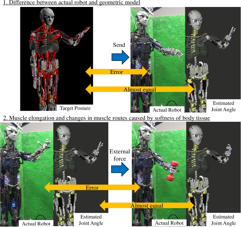
However, due to complexity of the body structure, there are several challenges in controlling tendon-driven musculoskeletal humanoids. The challenges arise from the difficulty to modelize these humanoids compared to the ordinary axis-driven humanoids [5]. There are mainly two problems (Fig. 1). First, the model error between the actual robot and its geometric model is very large, and the actual robot cannot move as intended in a simulation environment. Usually, we construct its geometric model, check its movements in a simulation environment, and then move the actual robot. However, tendon-driven musculoskeletal humanoids have many complex structures, such as multi-DOF joint structure of the spine and redundant muscles covering joints, and it is very difficult to modelize in detail. Thus, these humanoids cannot realize the intended joint angles and large internal muscle tension may emerge due to the large model error of antagonistic muscles (the upper figures of Fig. 1). Second, there are movements which the muscle length sensors cannot measure, due to changes in muscle routes caused by softness of body tissue. The muscles are deformed by emerging tension, its routes are changed by external force, and structures such as the rib can deform by muscle tension. For example, when tendon-driven musculoskeletal humanoids hold heavy objects, changes in muscle routes which the muscle length sensors cannot measure emerge, and so these humanoids cannot perceive self-body movements (the lower figures of Fig. 1).
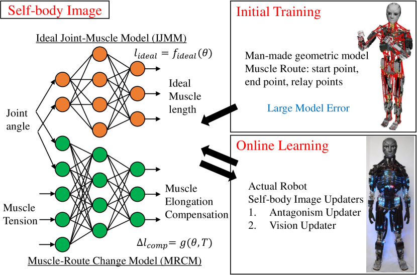
In the previous study [6], we solved the first problem by constructing joint-muscle model (JMM) which expresses the nonlinear relationship between joint angles and muscle lengths using a neural network (NN), and updating it online using the sensor information of actual robot. In this study, we expand this method and solve the two problems (Fig. 1) simultaneously. At first, we initialize the self-body image using a man-made geometric model, and then we update it using the sensor information of the actual robot. In the previous study, we expressed self-body image using only ideal joint-muscle model (IJMM). However, in this study, we express self-body image using two models: ideal joint-muscle model (IJMM) and muscle-route change model (MRCM), and update them simultaneously. By using this method, tendon-driven musculoskeletal humanoids become able to perceive self-body movements which do not appear as changes in muscle lengths, and can move as intended even when external forces are applied.
This paper is organized as follows. In Section I, we stated the motivation and goal of this study. In Section II, we will state the overview of this study: the definition of self-body image and the outline of this method. In Section III, we will state the initial training method of self-body image using a man-made geometric model. In Section IV, we will state the online learning method of self-body image using the sensor information of the actual robot. In Section V, we will conduct several experiments using this proposed system. Finally, in Section VI, we will state the conclusion and the future works.
II Overview of This Study
First, we will discuss how we define self-body image in this study and what kind of models can express the self-body image. Second, we wll state the overview of the proposed system in this study.
II-A Self-Body Image
Although there are several definitions of self-body image, in this study, we define the correct self-body image as “the state in which the robot can realize intended joint angles”. In the case of ordinary axis-driven humanoids, they have encoders in each joint and it is possible to realize the intended joint angles by using the feedback control against the error between the value of encoders and intended joint angles. However, as stated in Section I, tendon-driven musculoskeletal humanoids have many complex structures and do not have encoders in each joint, so it is difficult to modelize these humanoids in detail and realize the intended joint angles. In the previous study [6], we constructed joint-muscle mapping (JMM) which calculates muscle lengths realizing the intended joint angles using a neural network (NN), and then, updated it online using the sensor information of the actual robot in order to obtain a correct self-body image.
| (1) |
However, this method does not consider the muscle route changes caused by softness of body tissue, and so the robot cannot realize the intended joint angles in such situations as when external force is applied by holding a heavy object. Although these muscle-route changes do not appear as changes in muscle lengths, these appear as changes in muscle tensions . Thus, in this study, we express self-body image not by joint-muscle mapping but by joint-tension-length mapping (JTLM) as shown below.
| (2) |
Next, we discuss how we should modelize the function . First, in order to update the self-body image online using the sensor information of the actual robot, in this study, we express the function not by using table-search [7] and polynomial regression [8] which many previous studies use, but by using a NN. In this case, it is the simplest and easiest way to express the function as a NN in which the inputs are and , and the ouput is . However, there is a problem. When we update the NN online, we backpropagate the error between the output of the function and the sensor value of the actual robot. In doing so, we cannot decide if the backpropagated error is one between the actual robot and its geometric model, or one resulting from muscle-route changes caused by softness of body tissue. For this reason, even when the error is caused by softness of body tissue, self-body image has often been incorrectly updated in the direction to reduce the error between the actual robot and its geometric model. So, in this study, we divide self-body image into two models: ideal joint-muscle model (IJMM, ) in which no external forces are applied, and muscle-route change model (MRCM, ) which compensates for the muscle-route changes caused by softness of body-tissue.
| (3) |
By the construction of this model, we can choose which model to backpropagate the error to, and obtain self-body image stably and correctly. In this study, we each express these two models as a NN and propose the system to update them online.
II-B Overview of This System
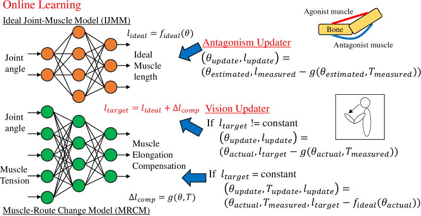
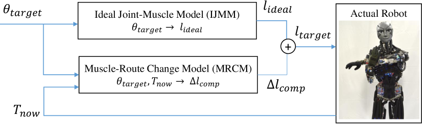
The overview of the proposed system is shown in Fig. 2. As stated in the previous Section II-A, self-body image is divided into two models: IJMM and MRCM, and each model is expressed using a NN. First, as shown in the upper right figure, we construct a data set using a man-made geometric model, train the respective models, and initialize the weight of these NNs. Second, as shown in the lower right figure, we update the two models online using the sensor information of the actual robot. There are two online updaters: Antagonism Updater and Vision Updater, and the Antagonism Updater updates the antagonism of IJMM, and the Vision Updater updates the IJMM and MRCM based on the information of the vision sensor.
In terms of high computational cost, these models are divided into body regions such as the neck, scapula, shoulder, and forearm, and to unify these models into one whole body model is a future task. As an example, we used a tendon-driven musculoskeletal humanoid Kengoro [4] in the experiments.
III Initial Training Using a Man-made Geometric Model
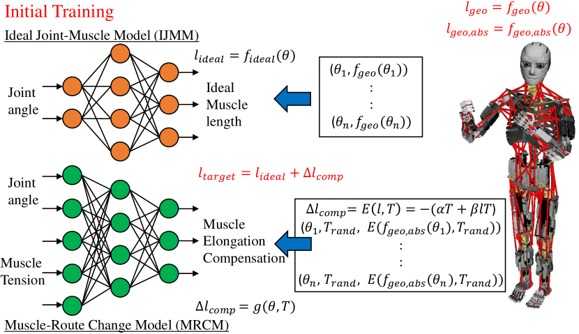
In this section, we will state the initial training method of IJMM and MRCM (Fig. 3).
III-A Ideal Joint-Muscle Model
As stated in Eq. 3, IJMM is the model which calculates the target muscle lengths from the target joint angles , in the ideal case that there are no muscle route changes caused by softness of body tissue. First, we make a geometric model of muscle routes in the tendon-driven musculoskeletal humanoid, for example, by expressing the start point, relay point, and end point of the muscle route. Also, in this study, we assume that the correct geometric model of the joint structures can be obtained by computer-aided design (CAD). Second, we move the joints of the geometric model to various angles, obtain the relative changes in muscle lengths from the initial posture (all joint angles are 0) by using the muscle routes of the geometric model, , and construct a data set of joint angles and muscle lengths (the upper right figure of Fig. 3). Finally, we train IJMM by using this data set.
III-B Muscle-Route Change Model
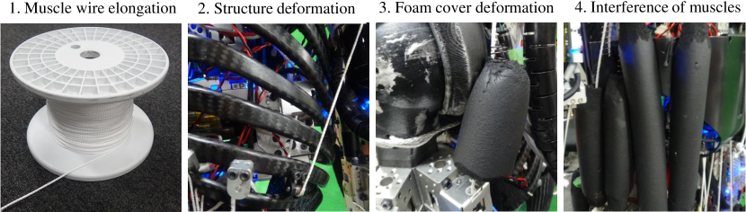
As stated in Eq. 3, MRCM is the model which compensates for muscle route changes caused by softness of body tissue, and which calculates the compensation value of muscle length from the target joint angles and muscle tensions . In order to initialize MRCM from a man-made geometric model, we must modelize the cause of muscle route changes to some extent. Then, we classify the muscle route changes caused by softness of body tissue into 4 groups (Fig. 4).
First, there is the elongation of Dyneema used as muscle wires [9]. As shown below, the elongation depends on and . is calculated from , so depends on and .
| (4) |
where is the spring constant of Dyneema per unit length, is the absolute length of the muscle. Also, we refer to variables which do not have the subscript as the relative muscle lengths from initial posture. Second, there is the deformation of structures such as the rib, and this basically depends on muscle tension . Third, because the muscles of the tendon-driven musculoskeletal humanoid Kengoro [4] have soft foam covers around the muscle wires in order to achieve softness of contact, and the muscle route changes occur when the foam covers deform due to large muscle tension. This depends on the size of the foam covers and how the muscles wind around the bone structure, and therefore, this depends on the muscle tension and the posture of the robot. Fourth, there is the interference among muscles which have soft foam covers, and this depends on the muscle tensions and the posture of the robot.
In short, MRCM depends on muscle tensions and the posture of the robot. In this study, in order to initialize MRCM, we use the elongation of muscle wires and deformation of the structure, which are easy to modelize, to calculate muscle lengths which should be compensated, , as shown below.
| (5) |
where the is a coefficient for the elongation of muscle wires ( in this study), is a coefficient for the deformation of the structure ( in this study), and is the function which calculates the absolute muscle lengths from the geometric model. is the muscle lengths which should be compensated, so it is a negative value. We change and randomly, calculate , and obtain the data set of joint angles, muscle tensions, and compensation value of muscle lengths (the lower right of Fig. 3). Finally, we train MRCM using the data set.
IV Online Self-body Image Acquisition Using The Actual Robot Data
In this section, we will explain the components of online learning: Antagonism Updater and Vision Updater, which are necessary to update IJMM and MRCM online from the sensor information of the actual robot (Fig. 5).
IV-A Online Learning
We will explain the estimation method of joint angles using muscle length, the estimation method of the actual joint angles using the vision sensor, and the learning methods of IJMM and MRCM, which are necessary to update IJMM and MRCM online.
First, we will state the method of joint angle estimation. Tendon-driven musculoskeletal humanoids have ball joints and flexible spine structures, so encoders cannot be installed and joint angles need to be estimated from the changes in muscle lengths. We use the method of Ookubo, et al. [8] using Extended Kalman Filter (EKF) for the joint angle estimation. In the method, we need JMM, , of the geometric model and the muscle jacobian, , which is the differentiated value of JMM. In this study, we substitute the self-body image, , and its differentiated value for the above JMM and muscle jacobian. Also, although Ookubo, et al. used the sensor value of muscle length, , as the observed value, we use the muscle length we send to the actual robot, , instead.
Second, we will state the joint angle estimation method of the actual robot, , from the vision sensor. The robot can obtain the relative position and posture of the hand from the eye, , by looking at the AR marker attached to the hand from the RGB camera attached to the head. Then, we obtain the joint angles of the actual robot by solving the Inverse Kinematics (IK) of the robot, where the initial joint angles are the estimated joint angles stated above, , the target position and posture is , and the links are the neck, thorax, collarbone, scapula, humerus, and forearm.
| (6) |
We have shown the effectiveness of online learning using these joint angles in a previous study [6].
Third, we will state the learning method of IJMM. When we update IJMM, we need a data set of joint angles and muscle lengths . However, if we use only this data set, over-fitting to the given the data set can occur. Taking into consideration that the joint angles and muscle lengths are 0 at the initial pose, and that the areas of the model except around the obtained data set should not be updated, and then, we update IJMM using the data set shown below as a minibatch.
| (7) |
where is randomized joint angles, and is the number of the .
Fourth, we will state the learning method of MRCM. When we update MRCM, we need a data set of joint angles, muscle tensions, and compensation values of muscle lengths, . The concept of the update is the same as in IJMM. Taking into consideration that the compensation values of muscle lengths are 0 when the muscle tensions are 0, and that the change of the compensation value is small when the posture of the robot changes, we update MRCM using the data set shown below as a minibatch.
| (8) | ||||
where is the randomized joint angles around .
IV-B Antagonism Updater
As stated in Section I, due to the model error between the actual robot and its geometric model, not only is the robot unable to realize the intended joint angles, but also the large internal muscle tension can emerge because of the wrong antagonistic relationship. The method to modify the antagonism is the Antagonism Updater, and this updates only IJMM. The rule of the update is shown as below.
| (9) |
where is the muscle lengths obtained from the encoders attached to the muscle actuators, is the current muscle tensions. The subscript stands for . Also, the update is executed only at the static state (when the change of is small) and only when has changed to some extent from the updated previously.
We will state the reason why the antagonism becomes better by this Antagonism Updater. We use the muscle stiffness control [10] when we send target muscle length to the actual robot as shown below.
| (10) |
In this control, the smaller the muscle stiffness is, the more the does not follow , permitting the error. So if we move the robot by the unfeasible antagonism, large internal muscle tension emerges, but the muscles settle down to a certain state by permitting the error. By updating IJMM using the current estimated joint angles and the feasible muscle lengths, the antagonism becomes correct and large internal muscle tension does not emerge. Also, although we stated that the muscle length of the actual robot does not follow the target muscle length because of muscle stiffness control, the compensation value of the error is considered into MRCM in addition to the 4 groups of Fig. 4.
IV-C Vision Updater
Vision Updater updates both IJMM and MRCM using the estimated joint angles of the actual robot, , obtained from vision sensor. The update rule of IJMM is as shown below.
| (11) | ||||
| (12) |
The update rule of MRCM is as shown below.
| (13) | ||||
| (14) |
where we abbreviated and as and . Also, the update is executed only at the static state (when the change of is small) and only when has changed to some extent from the updated previously.
In the update rule, means that the target muscle lengths do not change, so we do not send operating commands to the robot. When we do not send operating commands and changes from the previous value, external force is applied, and so we update MRCM, which expresses the compensation value of the muscle length by the applied force. To the contrary, when , we update IJMM. Thus, we fix one model: IJMM or MRCM, and update the other model. However, in the case that we update IJMM when external force is applied and operating commands are sent, the error which should be reflected to MRCM is reflected to IJMM. When we update IJMM, we need to check that external force is not applied to the contact sensors.
Practically, it is better that we update IJMM by Antagonism Updater and Vision Updater first, and after IJMM becomes correct, we update MRCM by applying external forces.
V Experiments
In this section, at first, we show the result of online learning and verify its effectiveness. Next, we show the effectiveness of joint angle estimation using the learned IJMM and MRCM. Finally, we conduct a grasping experiment of a heavy object and verify the effectiveness of the learned IJMM and MRC.
V-A Online Learning
We show the result of online learning of IJMM and MRCM. The effectiveness of the Antagonism Updater is verified in a previous study [6], so we show the effectiveness of the Vision Updater regarding IJMM and MRCM. Also in this study, each NN of IJMM and MRCM has 3 layers: an input layer, a hidden layer (1000 unit), and an output layer of muscle lengths, and the activation function is sigmoid. The unit of input joint angles is [rad], the unit of input muscle tension is (about 01), and the unit of output muscle lengths is [mm].
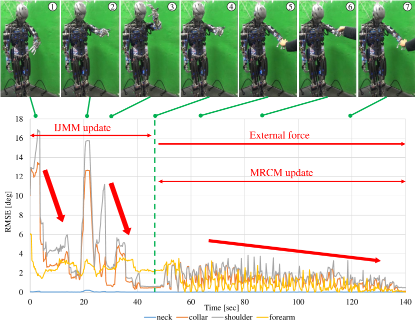
We show the result of online learning in Fig. 6. First, we send various joint angles to Kengoro, Kengoro looks at its hand, and we update self-body image using the Vision Updater. In this situation, is not constant and IJMM is updated. Next, in the situation that we do not send operating commands, by applying various external forces, we update MRCM. In all the movements of this experiment, the Antagonism Updater is also executed.
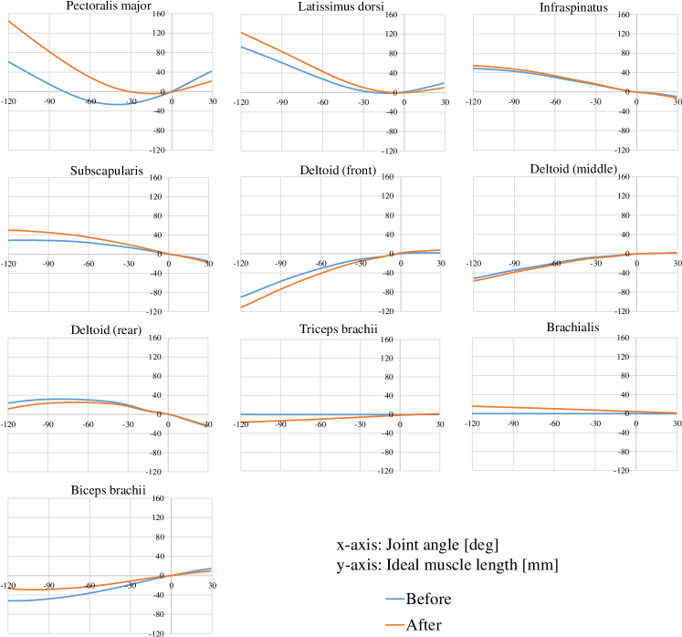
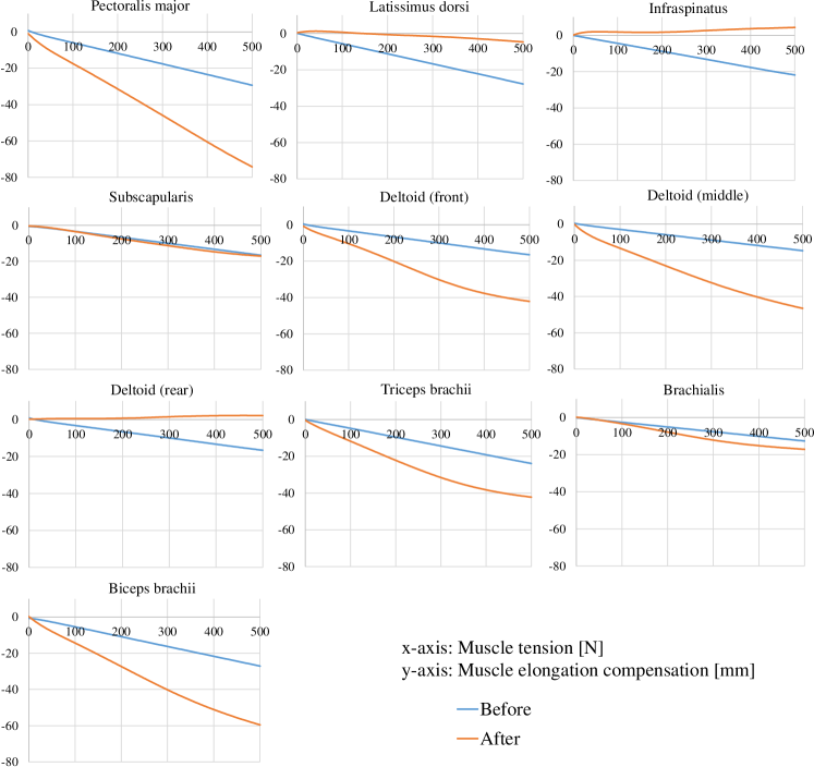
We show the transition graph of Root Mean Squared Error (RMSE) of the difference between the actual joint angles obtained from the vision sensor, , and estimated joint angles calculated from the current self-body image, , regarding joint groups such as the neck, scapula, shoulder, and forearm in the lower figure of Fig. 6. During the update of IJMM, RMSE was about 16 deg at first, and at the end, RMSE decreased to about 02 deg. Also, RMSE increased once at 20 sec, and this means that the posture moved largely from the posture updated at 05 sec and self-body image around the current posture was not learned yet. During the update of MRCM, RMSE decreased slowly. As stated in Section III-B, the model of MRCM is simplified and trained, so the obtaining of correct weight takes a long time. We show the comparison of IJMM between before and after online learning in Fig. 7. Also, we show the comparison of MRCM between before and after online learning in Fig. 8. We can see the MRCM was modified from the original geometric model by online learning. Also, at the deltoid (front) and triceps brachii, we can see the nonlinear spring feature of the actual robot muscles was learned.
V-B Joint Angle Estimation
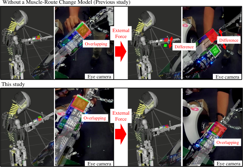
We compared the joint angle estimation using self-body image acquisition without MRCM conducted in a previous study [6] and the joint angle estimation using the proposed self-body image in this study. Under the condition that Kengoro keeps the posture, we applied external force and compared the change of the estimated joint angles. In this experiment, self-body image is learned previously and is not learned during this experiment.
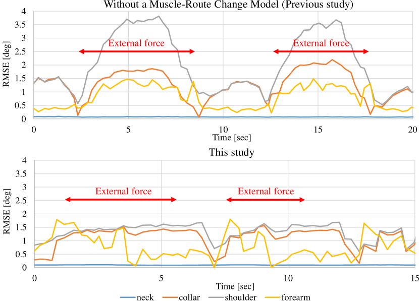
The result of the experiment is shown in Fig. 9. In the previous study (upper figure of Fig. 9), when the external force is applied, the estimated joint angles did not follow the actual joint angles, and there was a large error between self-body image and the actual robot. In comparison, in this study (lower figure of Fig. 9), even when the external force is applied, the estimated joint angles followed the actual joint angles, and better self-body image was acquired. We show the comparison of the transition of RMSE between the previous study and this study in Fig. 10. In the previous study, when the external force was applied, the RMSE of the shoulder rose up to about 4 deg, but in this study, the RMSE was within 2 deg.
V-C Heavy Object Grasping
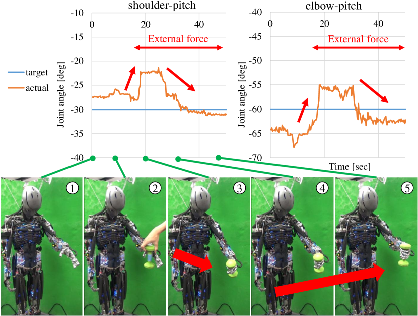
Finally, we show the control using self-body image which is learned in this study (Fig. 11). We conducted an experiment in which the robot grasps a heavy object (in this experiment, we used 1.4 kg dumbbell) and continues to keep the target posture. We show the result of the experiment and the graph which compares the target joint angles and the actual joint angles regarding the elbow and shoulder-pitch joints in Fig. 12.
First, the robot moves to the posture in which the shoulder pitch is -30 deg and the elbow is -60 deg, and grasps the dumbbell. The arm of the robot fell down because of the muscle route changes caused by softness of body tissue. However, by embedding a closed loop control to the change of muscle tension, which calculates compensation value of muscle length from current muscle tension and sends it to the robot, the posture of the robot went back to the original posture. In this experiment, the frequency of feedback control is low and the period of the compensation is long for better visual understandability.
VI CONCLUSION
In this study, we proposed an online learning method of self-body image considering muscle route changes caused by softness of body-tissue. In tendon-driven musculoskeletal humanoids, because of their body complexity, they are difficult to modelize, and there are several problems in controllability such as challenges in moving the actual robot as intended in a simulation environment, emergence of large internal muscle tension, and existence of movements which do not appear as changes in muscle lengths. To solve these problems, we constructed self-body image using a neural network and updated it online using the sensor information of the actual robot. To consider the muscle route changes which do not appear as changes in muscle lengths, we constructed self-body image that calculates target muscle lengths from the target joint angles and muscle tensions. Also, to learn self-body image correctly, we divided self-body image into two models: ideal joint-muscle model and muscle-route change model. First, we initialized the two models using a man-made geometric model. Second, we updated them online using two updaters: Antagonism Updater and Vision Updater to modify the model error between the actual robot and its geometric model. Finally, we showed effectiveness of this proposed system by the experiments of the joint angle estimation and grasping of a heavy object.
In future works, we would like to make the online learning of self-body image more stable. In order to make this method practical, we will consider how efficiently self-body image can be obtained using little actual robot sensor information. Also, we dealt with only the static state in this study, so next, we would like to deal with self-body image in a dynamic state.
References
- [1] Y. Nakanishi, S. Ohta, T. Shirai, Y. Asano, T. Kozuki, Y. Kakehashi, H. Mizoguchi, T. Kurotobi, Y. Motegi, K. Sasabuchi, J. Urata, K. Okada, I. Mizuuchi, and M. Inaba, “Design approach of biologically-inspired musculoskeletal humanoids,” International Journal of Advanced Robotic Systems, vol. 10, no. 4, p. 216, 2013.
- [2] S. Wittmeier, C. Alessandro, N. Bascarevic, K. Dalamagkidis, D. Devereux, A. Diamond, M. Jäntsch, K. Jovanovic, R. Knight, H. G. Marques, P. Milosavljevic, B. Mitra, B. Svetozarevic, V. Potkonjak, R. Pfeifer, A. Knoll, and O. Holland, “Toward anthropomimetic robotics: Development, simulation, and control of a musculoskeletal torso,” Artificial Life, vol. 19, no. 1, pp. 171–193, 2013.
- [3] M. Jäntsch, S. Wittmeier, K. Dalamagkidis, A. Panos, F. Volkart, and A. Knoll, “Anthrob - A Printed Anthropomimetic Robot,” in Proceedings of the 2013 IEEE-RAS International Conference on Humanoid Robots, 2013, pp. 342–347.
- [4] Y. Asano, T. Kozuki, S. Ookubo, M. Kawamura, S. Nakashima, T. Katayama, Y. Iori, H. Toshinori, K. Kawaharazuka, S. Makino, Y. Kakiuchi, K. Okada, and M. Inaba, “Human Mimetic Musculoskeletal Humanoid Kengoro toward Real World Physically Interactive Actions,” in Proceedings of the 2016 IEEE-RAS International Conference on Humanoid Robots, 2016, pp. 876–883.
- [5] K. Hirai, M. Hirose, Y. Haikawa, and T. Takenaka, “The Development of Honda Humanoid Robot,” in Proceedings of The 1998 IEEE International Conference on Robotics and Automation, 1998, pp. 1321–1326.
- [6] K. Kawaharazuka, S. Makino, M. Kawamura, Y. Asano, K. Okada, and M. Inaba, “Online Learning of Joint-Muscle Mapping using Vision in Tendon-driven Musculoskeletal Humanoids,” IEEE Robotics and Automation Letters, vol. 3, no. 2, pp. 772–779, 2018.
- [7] Y. Nakanishi, K. Hongo, I. Mizuuchi, and M. Inaba, “Joint proprioception acquisition strategy based on joints-muscles topological maps for musculoskeletal humanoids,” in Proceedings of The 2010 IEEE International Conference on Robotics and Automation, 2010, pp. 1727–1732.
- [8] S. Ookubo, Y. Asano, T. Kozuki, T. Shirai, K. Okada, and M. Inaba, “Learning nonlinear muscle-joint state mapping toward geometric model-free tendon driven musculoskeletal robots,” in Proceedings of the 2015 IEEE-RAS International Conference on Humanoid Robots, 2015, pp. 765–770.
- [9] Y. Asano, T. Kozuki, S. Ookubo, K. Kawasaki, T. Shirai, K. Kimura, K. Okada, and M. Inaba, “A Sensor-driver Integrated Muscle Module with High-tension Measurability and Flexibility for Tendon-driven Robots,” in Proceedings of the 2015 IEEE/RSJ International Conference on Intelligent Robots and Systems, 2015, pp. 5960–5965.
- [10] T. Shirai, J. Urata, Y. Nakanishi, K. Okada, and M. Inaba, “Whole body adapting behavior with muscle level stiffness control of tendon-driven multijoint robot,” in Proceedings of the 2011 IEEE International Conference on Robotics and Biomimetics, 2011, pp. 2229–2234.